Cover - Penthouse (Remove and Replace)
Correction code 1610100216101002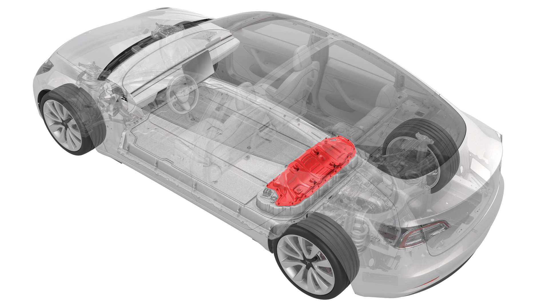
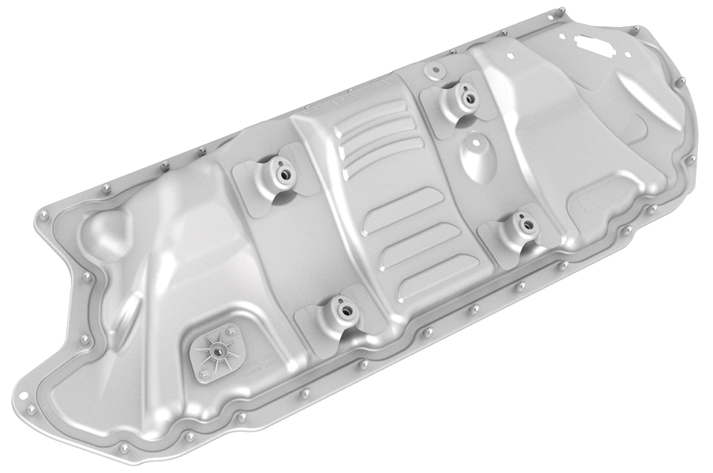
- 1127845-00-AAsy, Service Cover, Penthouse, Model 3
- 1059330-00-BSkt, 1/4in Dr, 5-Lobe Torx Plus External
- 1076971-02-AWrench, Torque + Angle, 1/4" Dr
- 1108272-00-BCap, Logic Conn, Inv, 3DU
SPECIAL TOOLS
Asy, Service Cover, Penthouse, Model 3 (1127845-00-A) |
Skt, 1/4in Dr, 5-Lobe Torx Plus External (1059330-00-B) |
Wrench, Torque + Angle, 1/4" Dr (1076971-02-A) |
Cap, Logic Conn, Inv, 3DU (1108272-00-B) |
 Warning: Remove all jewelry (watches, bracelets, rings, necklaces, earrings, ID tags, piercings, etc.) from your person, and all objects (keys, coins, pens, pencils, tools, fasteners, etc.) from your pockets before performing any procedure that exposes you to high voltage.Warning: If corrective eyewear is necessary to safely perform any procedure, make sure that the eyewear is securely restrained to the head and cannot fall off.Warning:
Only technicians who have been trained in High Voltage Awareness are permitted to perform this procedure. Proper personal protective equipment (PPE) and insulating HV gloves with a minimum rating of class 0 (1000V) must be worn at all times a high voltage cable, busbar, or fitting is handled. Refer to Tech Note TN-15-92-003, "High Voltage Awareness Care Points" for additional safety information.
Remove
-
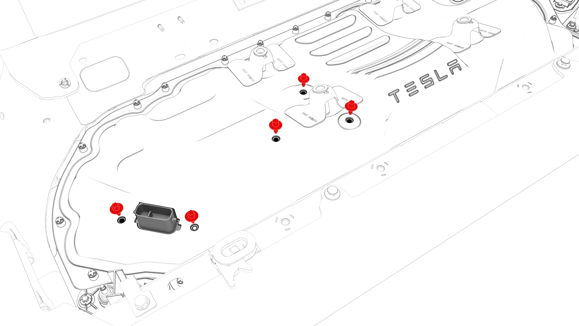
Release the clips that attach the low voltage electrical harness to the charge port to HV battery harness bracket at the penthouse.
-
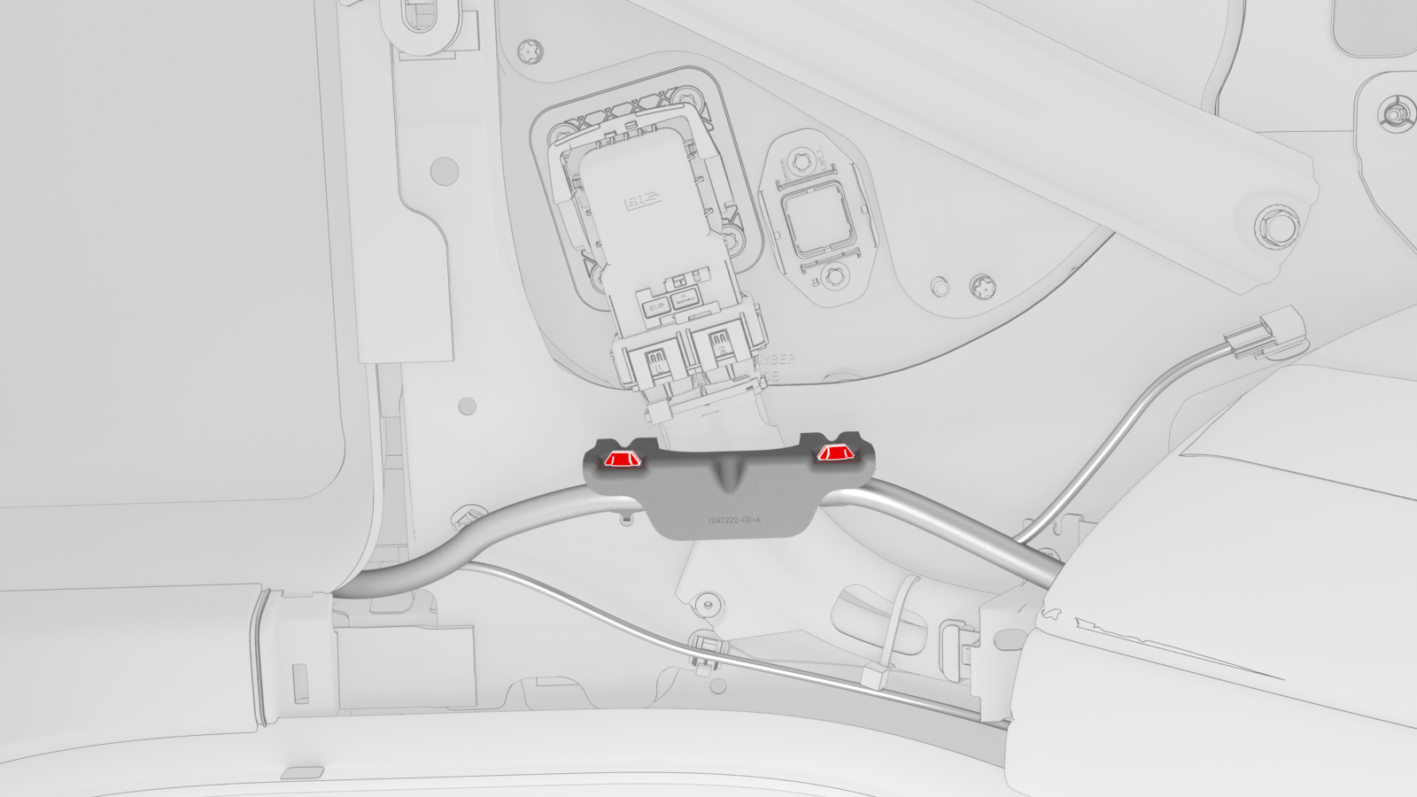
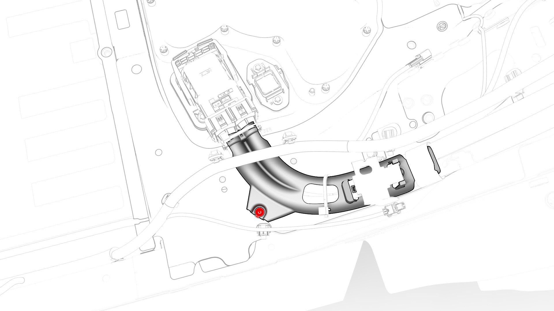
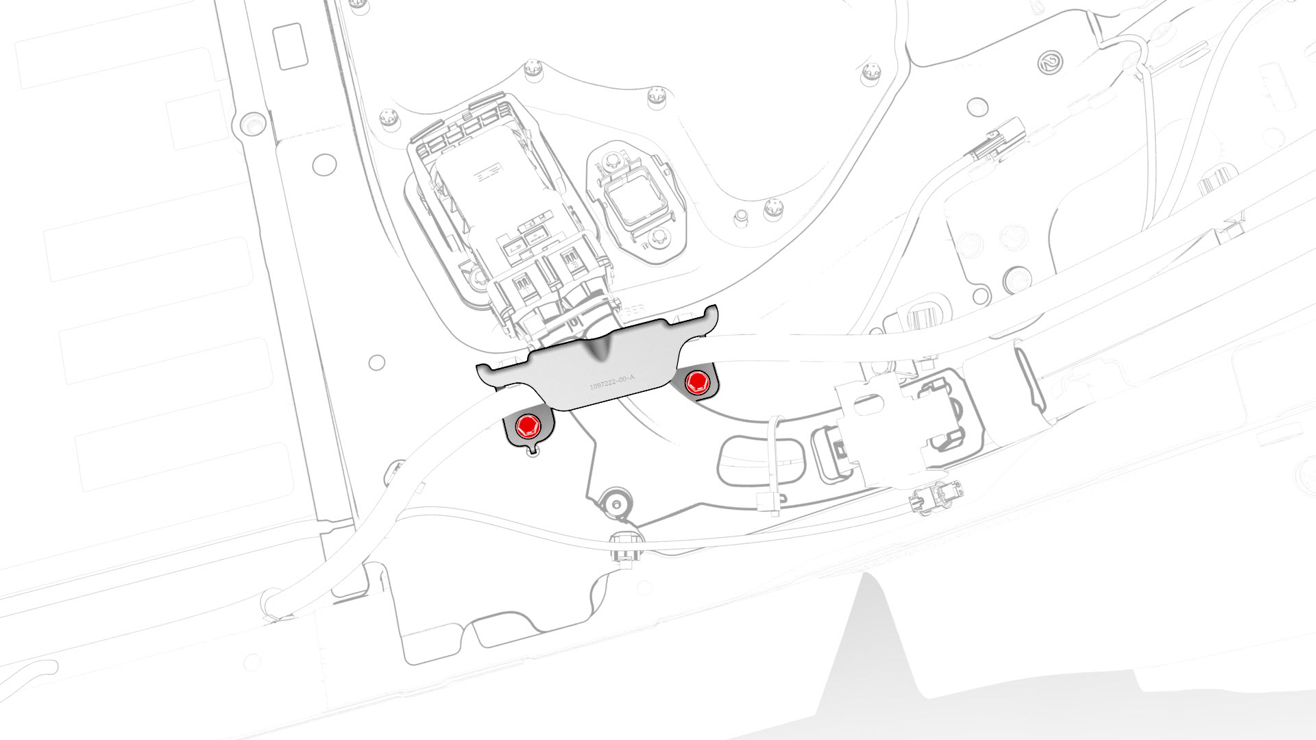
Remove the bolts that attach the charge port to HV battery harness bracket at the penthouse, and then remove the bracket from the vehicle.
 Torque 10 Nm
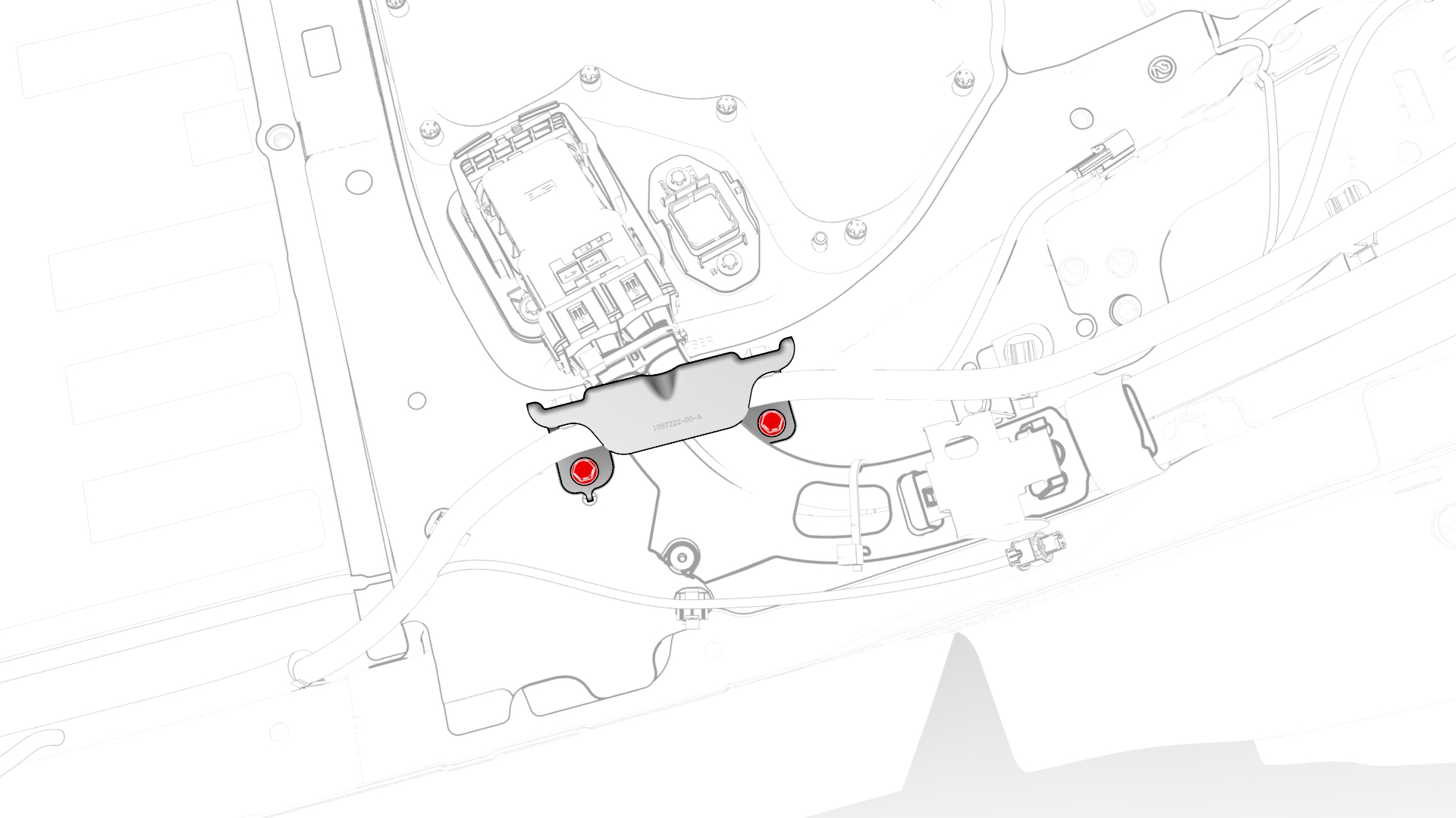
-
Release the clip that attaches the charge port electrical harness to the vehicle.
-
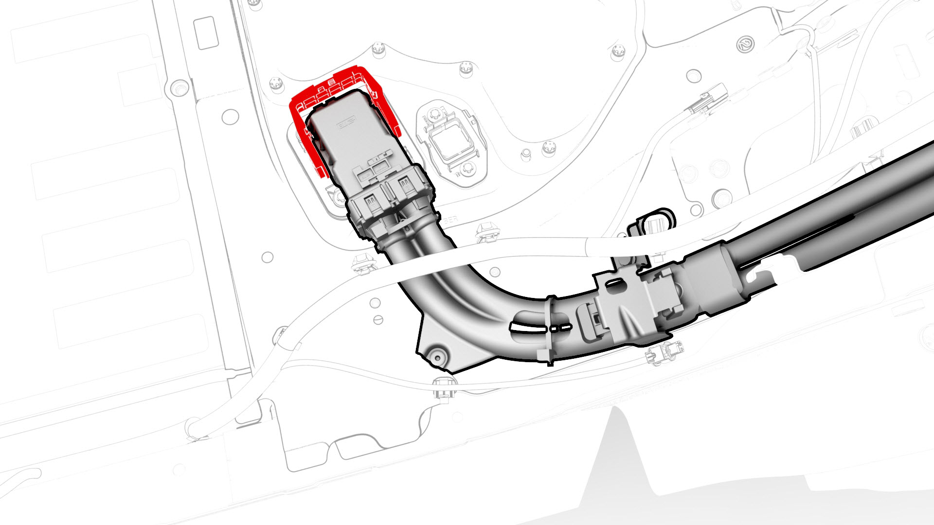
Slide the security tab to the unlock position, release the locking handle, and then disconnect the charge port electrical harness from the penthouse DC input connector.
-
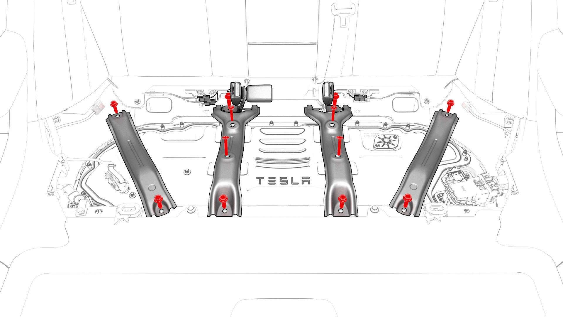
Remove the bolts that attach the penthouse rails to the body and penthouse cover, and then remove the rails from the vehicle.
-
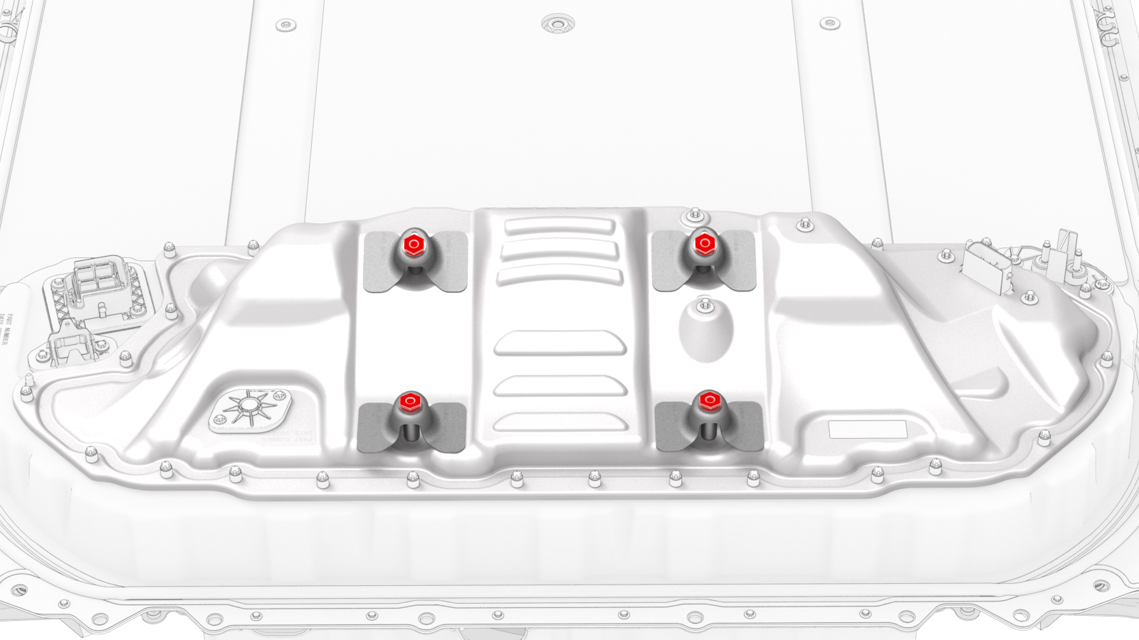
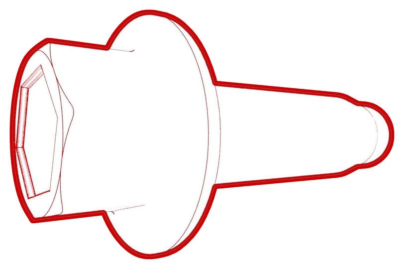
If the penthouse cover is to be replaced with a new cover, turn the adjustable elements (x4) clockwise to remove them from the penthouse cover.
-
Remove and discard the bolts that attach the high voltage controller internally to the penthouse cover.
 28-Bolt Penthouse Cover
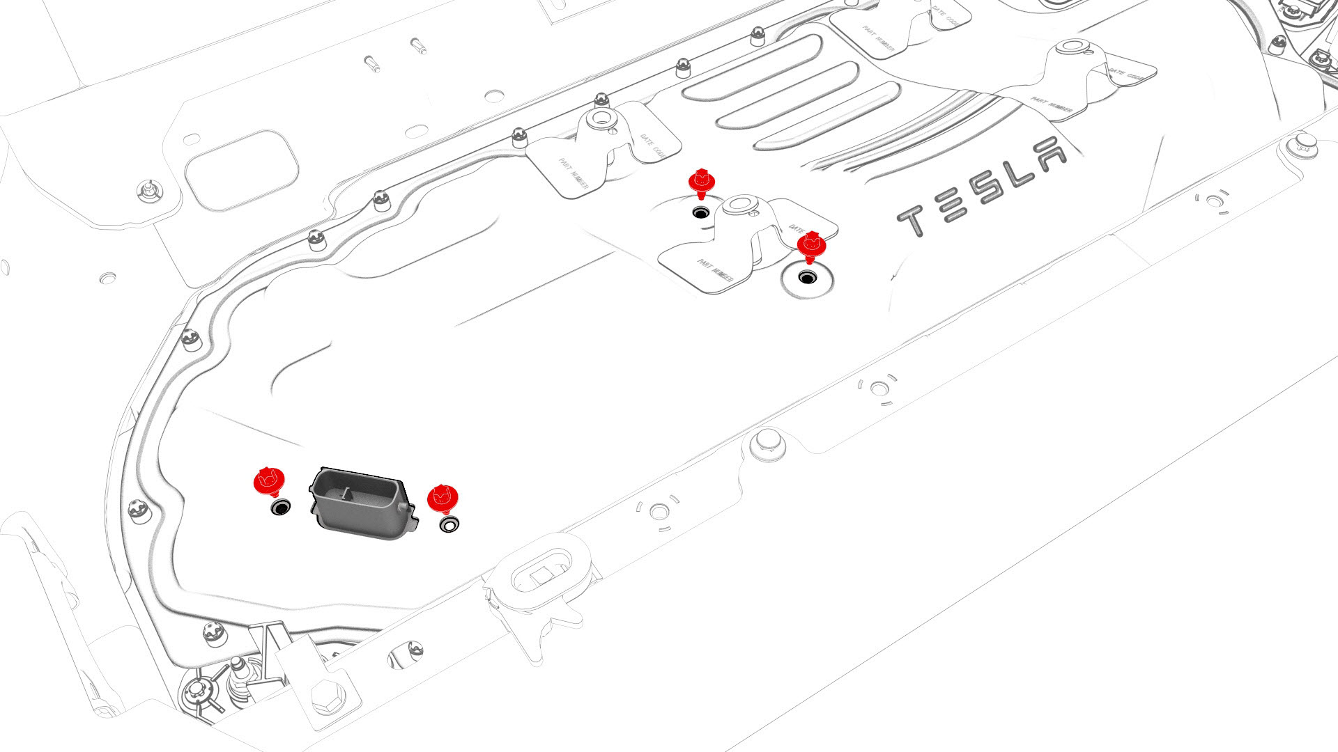 Retrofit Patch, 18-Bolt, and 16-Bolt Penthouse Covers
 -
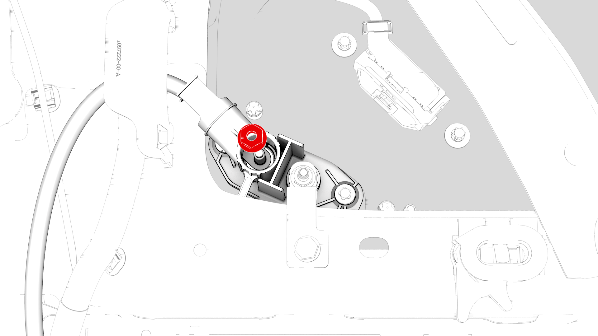
Remove and discard the nut that attaches the positive 12V output cable to the DCDC passthrough, and then remove the cable from the passthrough.
Note: Inspect the condition of the rubber boot at the end of the output cable, and replace the boot if it is melted or damaged.
-
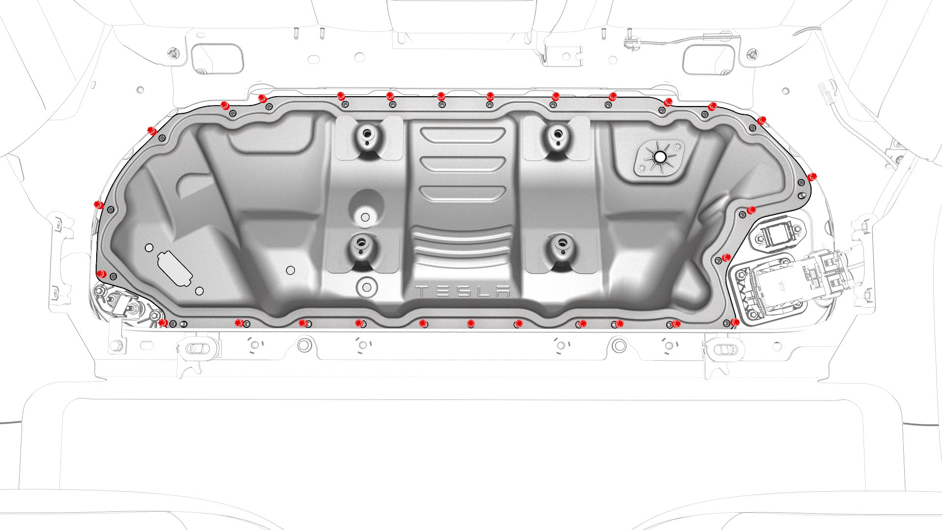
Fully loosen and remove (if possible) the bolts that attach the penthouse cover to the HV battery.
Note: Different penthouse cover revisions have 28, 18, or 16 bolts.
-
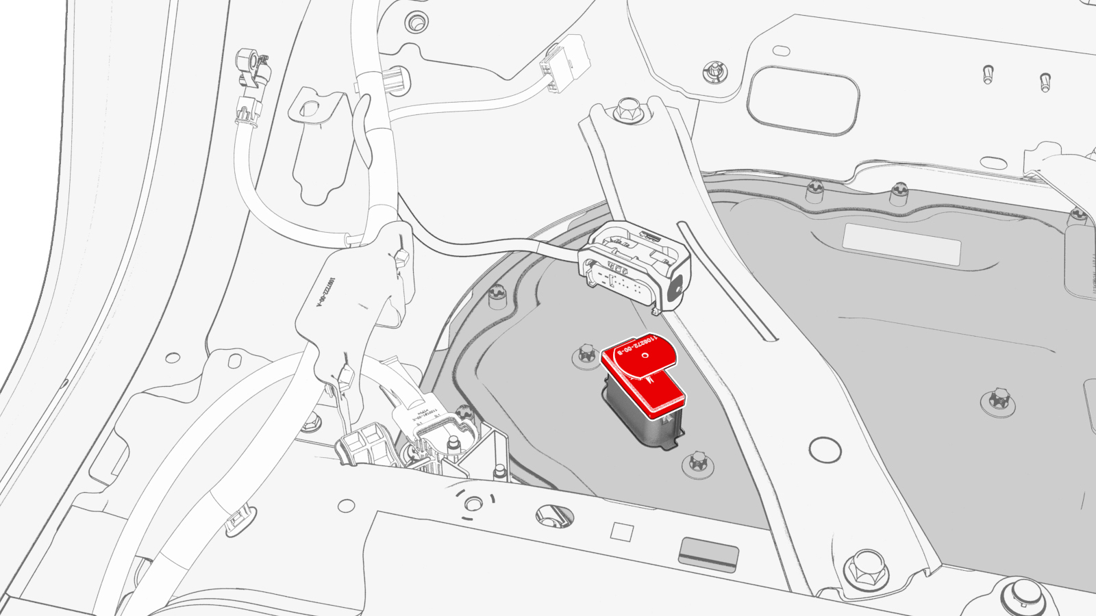
Remove the logic connector cap from the high voltage controller connector.
-
Remove the penthouse cover from the vehicle.
-
Reinstall the logic connector cap onto the high voltage controller connector.
-
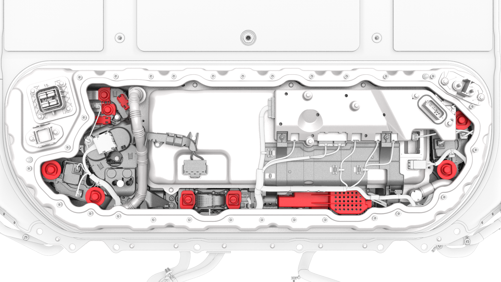
Visually inspect the interior of the penthouse for any presence of leaked coolant.
Note: Areas of interest are the coolant input and output tubes and fittings, and around the perimeter of the penthouse.
 Caution:If any leaked coolant is found, escalate a Toolbox session.
 -
Visually inspect the interior of the penthouse for insulators on the high voltage components.
- If any of the insulators are missing, install the missing insulators. See Insulators - HV Battery (Install).
- If all of the insulators are installed, continue to the procedure that required the penthouse cover to be removed.
| 1 | Perform the vehicle electrical isolation procedure. See Vehicle Electrical Isolation Procedure. | ||
| 2 | Remove the foam cover from the LH side of the penthouse. | ||
| 3 | Remove the LH rear sill panel trim. See Trim - Sill Panel - Rear - LH (Remove and Replace). | ||
| 4 | Release the clips that attach the low voltage electrical harness to the charge port to HV battery harness bracket at the penthouse. | |
| 5 | Remove the bolts that attach the charge port to HV battery harness bracket at the penthouse, and then remove the bracket from the vehicle. Torque 10 Nm | |
| 6 | Release the clip that attaches the charge port electrical harness to the vehicle. | |
| 7 | Slide the security tab to the unlock position, release the locking handle, and then disconnect the charge port electrical harness from the penthouse DC input connector. | |
| 8 | Remove the LH 2nd row buckle. See Buckle - 2nd Row - LH (Remove and Replace). | ||
| 9 | Remove the center 2nd row buckle. See Buckle - 2nd Row - Center (Remove and Replace). | ||
| 10 | Remove the bolts that attach the penthouse rails to the body and penthouse cover, and then remove the rails from the vehicle. | |
| 11 | If the penthouse cover is to be replaced with a new cover, turn the adjustable elements (x4) clockwise to remove them from the penthouse cover. | |
28-Bolt Penthouse Cover
Retrofit Patch, 18-Bolt, and 16-Bolt Penthouse Covers
| 12 | Remove and discard the bolts that attach the high voltage controller internally to the penthouse cover. | |
| 13 | Release the cover on the positive 12V output cable, at the DCDC passthrough. | ||
| 14 | Remove and discard the nut that attaches the positive 12V output cable to the DCDC passthrough, and then remove the cable from the passthrough. Note: Inspect the condition of the rubber boot at the end of the output cable, and replace the boot if it is melted or damaged.
| |
| 15 | Fully loosen and remove (if possible) the bolts that attach the penthouse cover to the HV battery. Note: Different penthouse cover revisions have 28, 18, or 16 bolts.
| |
| 16 | Remove the logic connector cap from the high voltage controller connector. | |
| 17 | Remove the penthouse cover from the vehicle. | ||
| 18 | Reinstall the logic connector cap onto the high voltage controller connector. | |
| 19 | Visually inspect the interior of the penthouse for any presence of leaked coolant. Note: Areas of interest are the coolant input and output tubes and fittings, and around the perimeter of the penthouse.
Caution: If any leaked coolant is found, escalate a Toolbox session.
| ||
| 20 | Visually inspect the interior of the penthouse for insulators on the high voltage components.
|
Install
Caution:
Replace all patchbolts.
Replace all nyloc nuts.
-
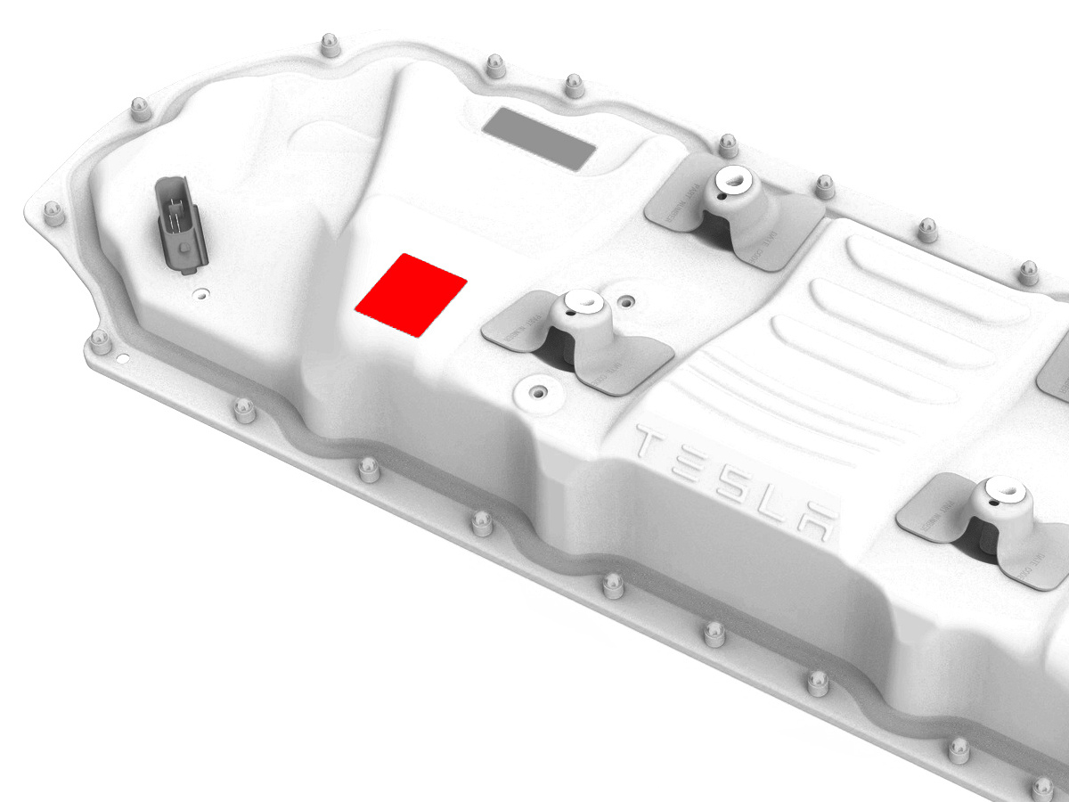
If the aluminum tape retrofit patch is damaged, remove it, clean the area with an IPA wipe, apply another 50mm x 50mm patch of aluminum tape, and wet out the patch with a silicone roller to set the adhesive.
-
Remove the logic connector cap from the high voltage controller connector.
-
Install the penthouse cover on the HV battery, and then hand-tighten the bolts.
Note: Different penthouse cover revisions have 28, 18, or 16 bolts.
-
Reinstall the logic connector cap onto the high voltage controller connector.
-
Torque the penthouse cover bolts in the sequence shown, and mark each with a green paint pen as they are torqued.
 Torque 8 Nm
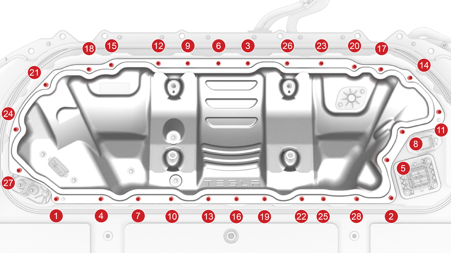 28-Bolt Penthouse Cover Torque Sequence
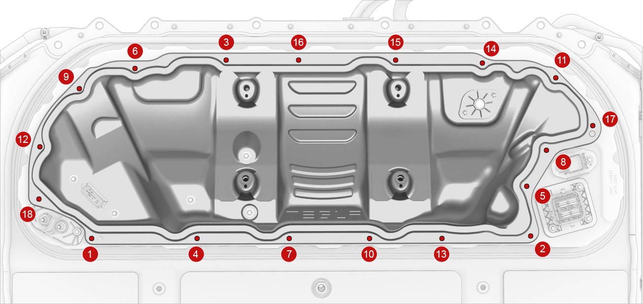 18-Bolt Penthouse Cover Torque Sequence
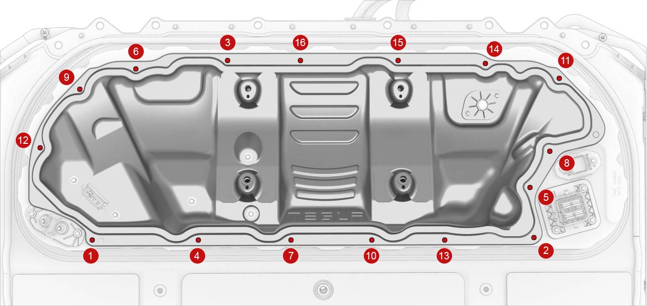 16-Bolt Penthouse Cover Torque Sequence
 -
Connect the positive 12V output cable to the DCDC passthrough, install a new nut to attach the cable, and mark the nut with a green paint pen after torque.
 Torque 9 NmCaution:Make sure that the rubber boot is not trapped under the cable lug or pinched between the cable lug and nut.
 -
Install and hand-tighten new bolts that attach the high voltage controller internally to the penthouse cover.
28-Bolt Penthouse Cover
Retrofit Patch, 18-Bolt, and 16-Bolt Penthouse Covers
-
Torque the high voltage controller to penthouse cover bolts in the sequence shown, and mark each bolt with a green paint pen as they are torqued.
 Torque Plastisol Gasket Bolts 5 Nm +90 degTorque Gasketless Bolts 5 Nm +20 degCaution:Insufficient torque of bolts 1 and 2 opens the high voltage interlock loop circuit.
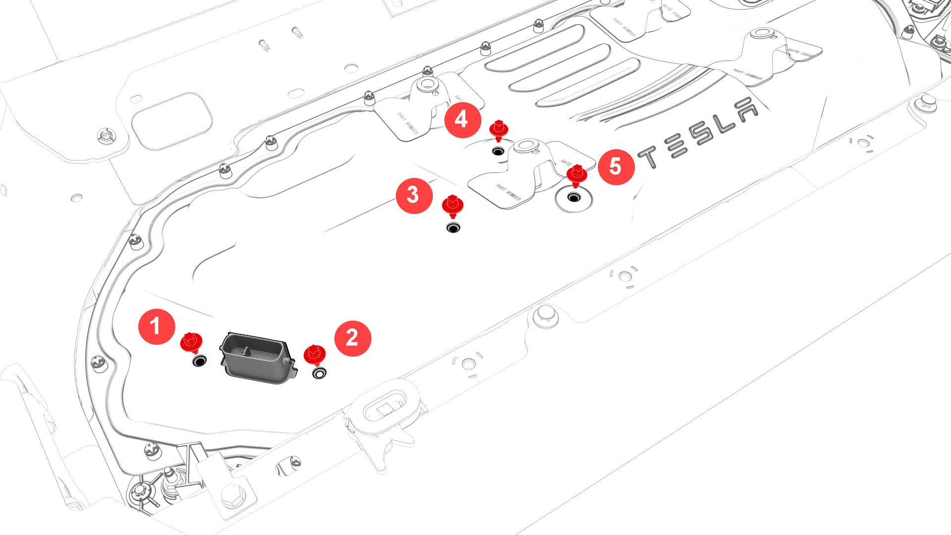 28-Bolt Penthouse Cover
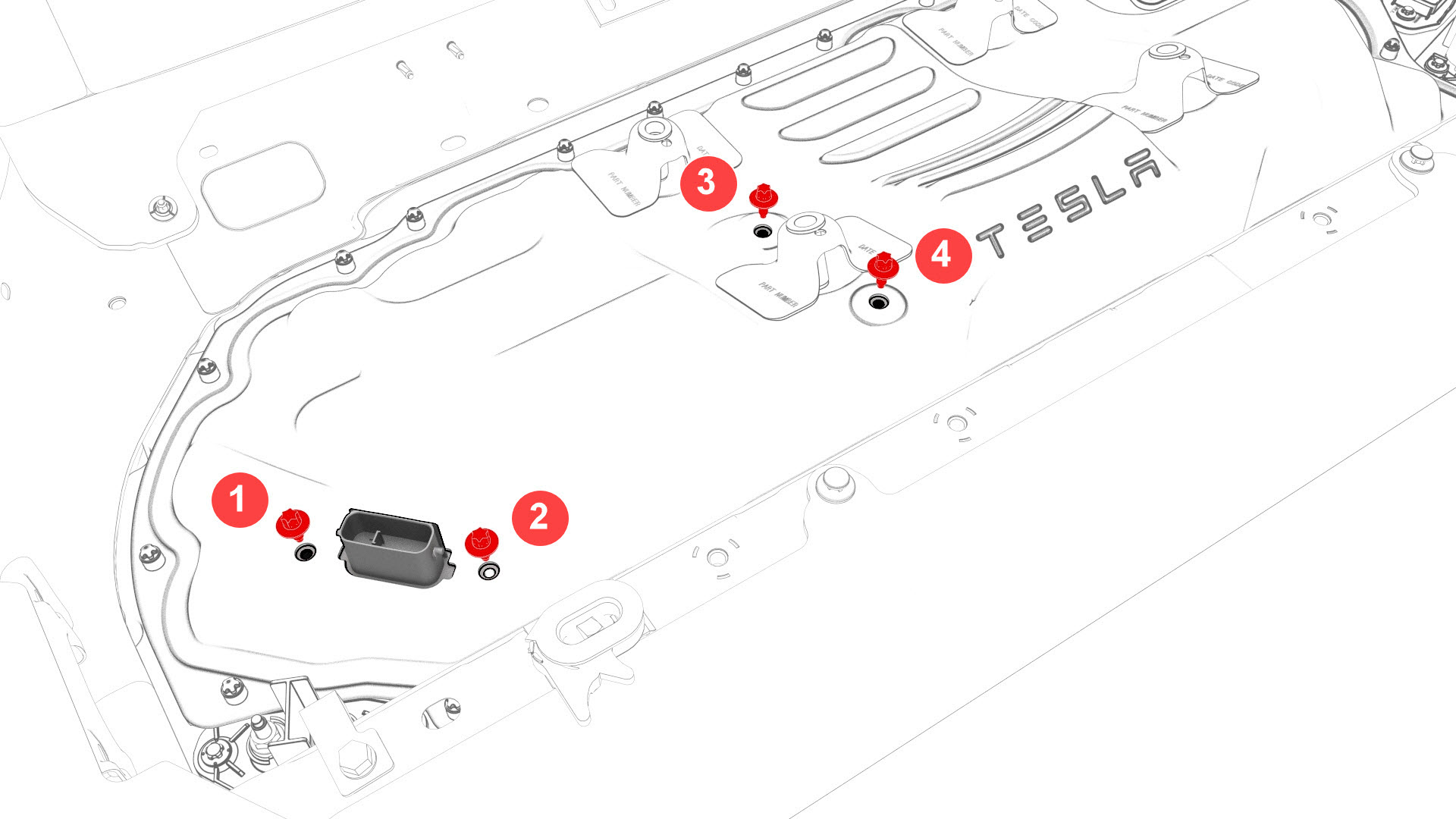 Retrofit Patch, 18-Bolt, and 16-Bolt Penthouse Covers
 -
Install and hand-tighten the adjustable elements (x4) on the penthouse cover counter-clockwise so that they are fully engaged.
Caution:Hand-tighten only.
-
Install the penthouse rails to the body and penthouse cover, and then install and hand-tighten the bolts that attach the rails to the body and cover.
-
Torque the bolts to specification.
 Torque 24 Nm
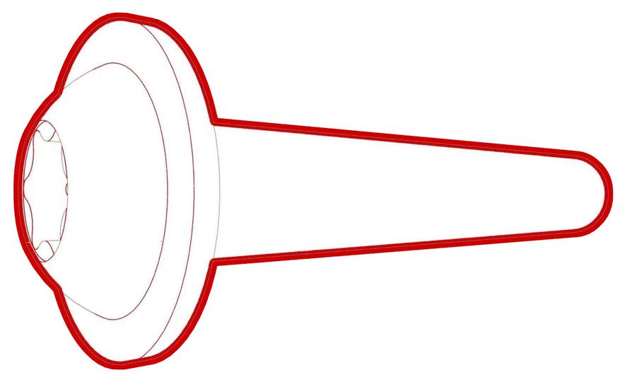 Torque 24 Nm
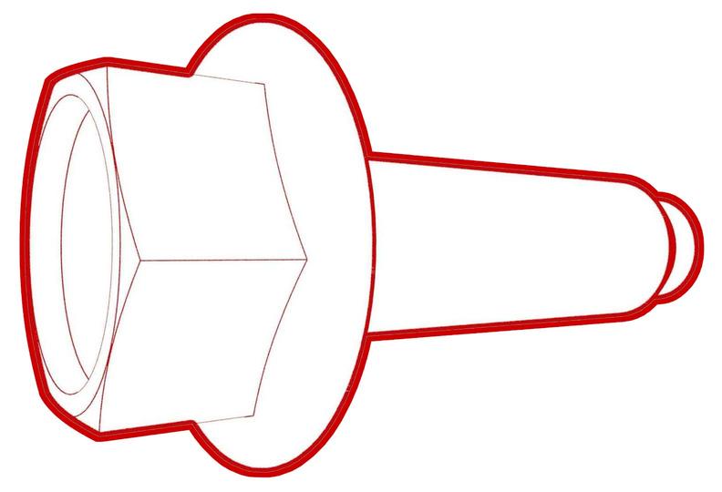 Torque 24 Nm
 -
Connect the charge port electrical harness to the penthouse DC input connector. Close the locking handle and slide the security tab to the lock position.
-
Fasten the clip that attaches the charge port electrical harness to the vehicle.
-
Install the charge port to HV battery harness bracket to the body, and install the bolts that attach the bracket to the body.Torque 10 Nm
-
Fasten the clips that attach the low voltage electrical harness to the charge port to HV battery harness bracket at the penthouse.
| 1 | Use an IPA wipe to clean any residue from the high voltage controller mounting bolt holes and both the inside and outside of the penthouse cover at the bolt holes. | ||
| 2 | If the aluminum tape retrofit patch is damaged, remove it, clean the area with an IPA wipe, apply another 50mm x 50mm patch of aluminum tape, and wet out the patch with a silicone roller to set the adhesive. | |
| 3 | Use IPA wipes to clean the mating surface of the HV battery and the penthouse cover gasket. | ||
| 4 | Remove the logic connector cap from the high voltage controller connector. | |
| 5 | Install the penthouse cover on the HV battery, and then hand-tighten the bolts. Note: Different penthouse cover revisions have 28, 18, or 16 bolts.
| |
| 6 | Reinstall the logic connector cap onto the high voltage controller connector. | |
28-Bolt Penthouse Cover Torque Sequence
18-Bolt Penthouse Cover Torque Sequence
16-Bolt Penthouse Cover Torque Sequence
| 7 | Torque the penthouse cover bolts in the sequence shown, and mark each with a green paint pen as they are torqued. Torque 8 Nm | |
| 8 | Connect the positive 12V output cable to the DCDC passthrough, install a new nut to attach the cable, and mark the nut with a green paint pen after torque. Torque 9 Nm Caution: Make sure that the rubber boot is not trapped under the cable lug or pinched between the cable lug and nut.
| |
| 9 | Replace the cover on the positive 12V output cable at the DCDC passthrough, and then press down to attach the cover. | ||
28-Bolt Penthouse Cover
Retrofit Patch, 18-Bolt, and 16-Bolt Penthouse Covers
| 10 | Install and hand-tighten new bolts that attach the high voltage controller internally to the penthouse cover. | |
28-Bolt Penthouse Cover
Retrofit Patch, 18-Bolt, and 16-Bolt Penthouse Covers
| 11 | Torque the high voltage controller to penthouse cover bolts in the sequence shown, and mark each bolt with a green paint pen as they are torqued. Torque Plastisol Gasket Bolts 5 Nm +90 deg Torque Gasketless Bolts 5 Nm +20 deg Caution: Insufficient torque of bolts 1 and 2 opens the high voltage interlock loop circuit.
| |
| 12 | Perform a penthouse air leak test. See Penthouse Air Leak Test. | ||
| 13 | Install and hand-tighten the adjustable elements (x4) on the penthouse cover counter-clockwise so that they are fully engaged. Caution: Hand-tighten only.
| |
| 14 | Install the penthouse rails to the body and penthouse cover, and then install and hand-tighten the bolts that attach the rails to the body and cover. | |
| 15 | Torque the bolts to specification. Torque 24 Nm Torque 24 Nm Torque 24 Nm | ||
| 16 | Install the center 2nd row buckle. See Buckle - 2nd Row - Center (Remove and Replace). | ||
| 17 | Install the LH 2nd row buckle. See Buckle - 2nd Row - LH (Remove and Replace). | ||
| 18 | Connect the charge port electrical harness to the penthouse DC input connector. Close the locking handle and slide the security tab to the lock position. | |
| 19 | Fasten the clip that attaches the charge port electrical harness to the vehicle. | |
| 20 | Install the charge port to HV battery harness bracket to the body, and install the bolts that attach the bracket to the body. Torque 10 Nm | |
| 21 | Fasten the clips that attach the low voltage electrical harness to the charge port to HV battery harness bracket at the penthouse. | |
| 22 | Install the LH rear sill panel trim. See Trim - Sill Panel - Rear - LH (Remove and Replace). | ||
| 23 | Install the foam cover to the LH side of the penthouse. | ||
| 24 | Connect 12V power. See 12V Power (Disconnect and Connect). |