HV Header - Inverter - Rear Drive Unit (Remove and Replace)
Correction code 4020630240206302
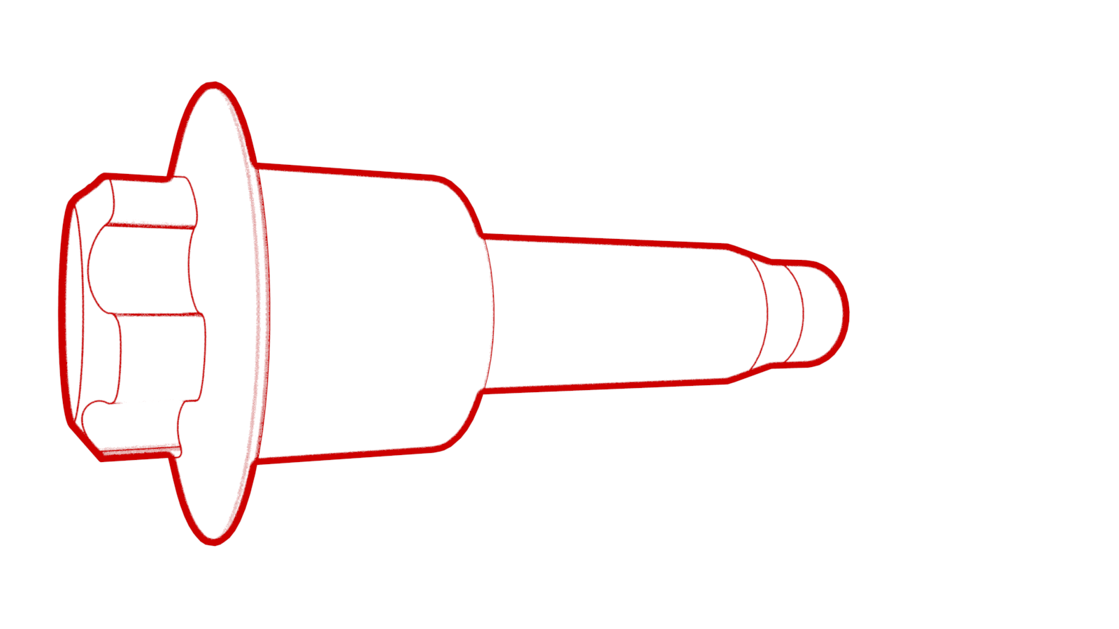
- 1142608-00-B Extractor, Drive Unit HV Header, Model 3
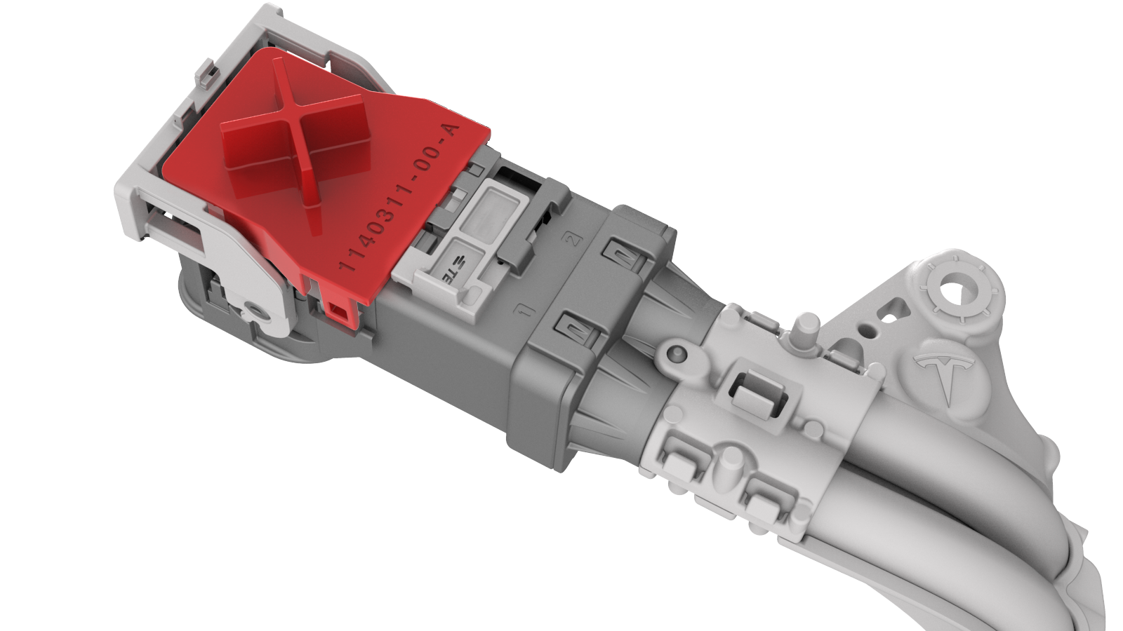
- 1140311-00-ALever Lock, HV Connector, Model 3
SPECIAL TOOLS
Extractor, Drive Unit HV Header, Model 3 (1142608-00-B) |
Lever Lock, HV Connector, Model 3 (1140311-00-A) |
 Warning:
Only technicians who have been trained in High Voltage Awareness are permitted to perform this procedure. Proper personal protective equipment (PPE) and insulating HV gloves with a minimum rating of class 0 (1000V) must be worn at all times a high voltage cable, busbar, or fitting is handled. Refer to Tech Note TN-15-92-003, "High Voltage Awareness Care Points" for additional safety information.
Remove
-
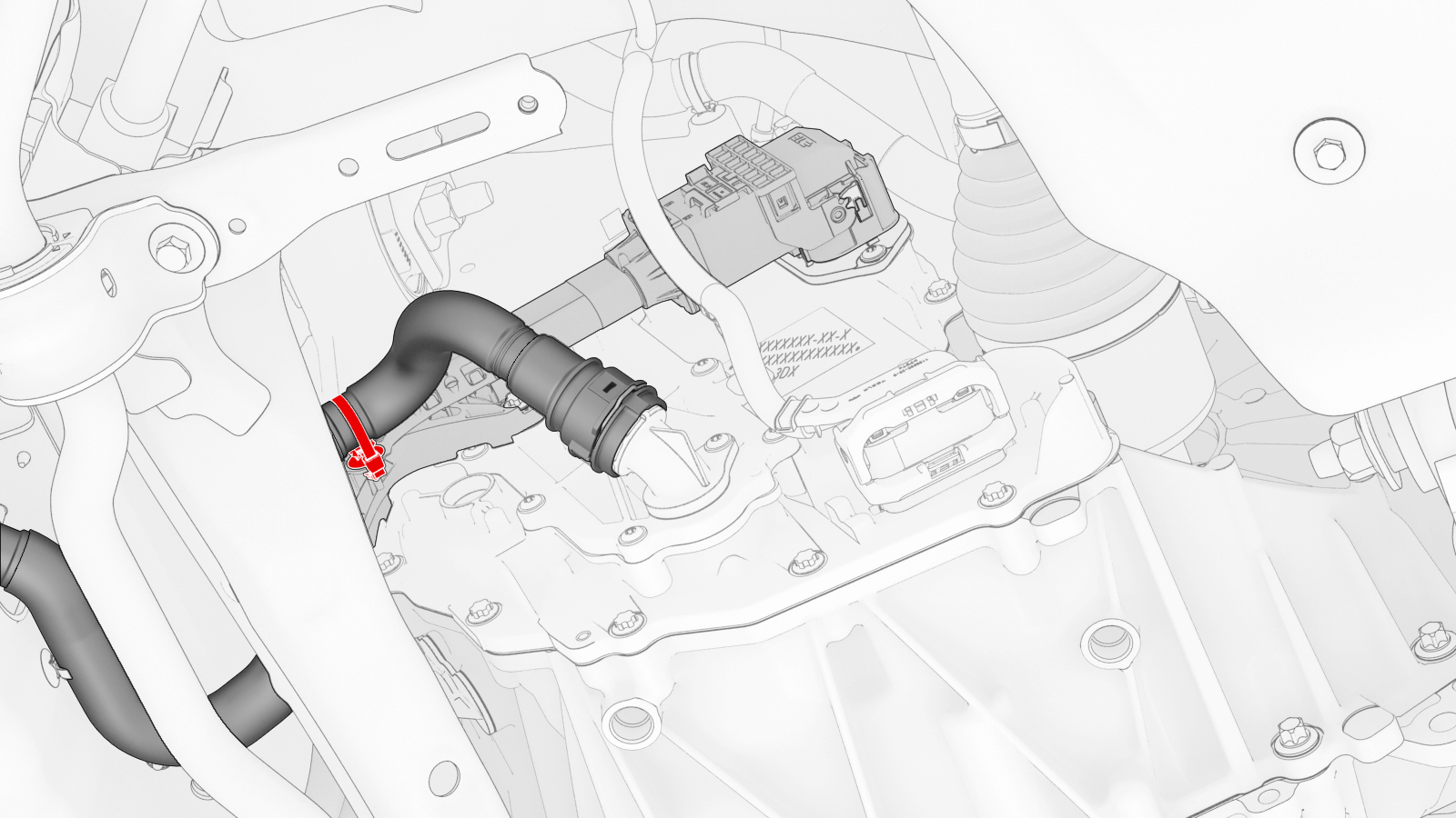
Release the clip that attaches the rear drive unit inlet hose to the rear drive unit inverter.
-
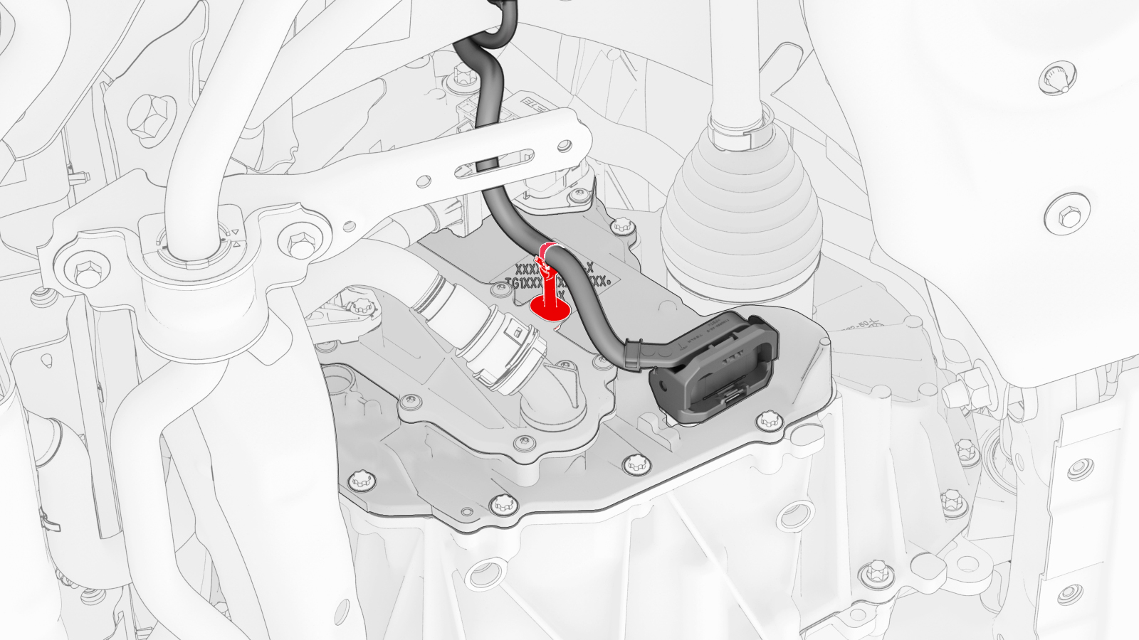
Disconnect the low voltage electrical harness from the inverter connector.
-
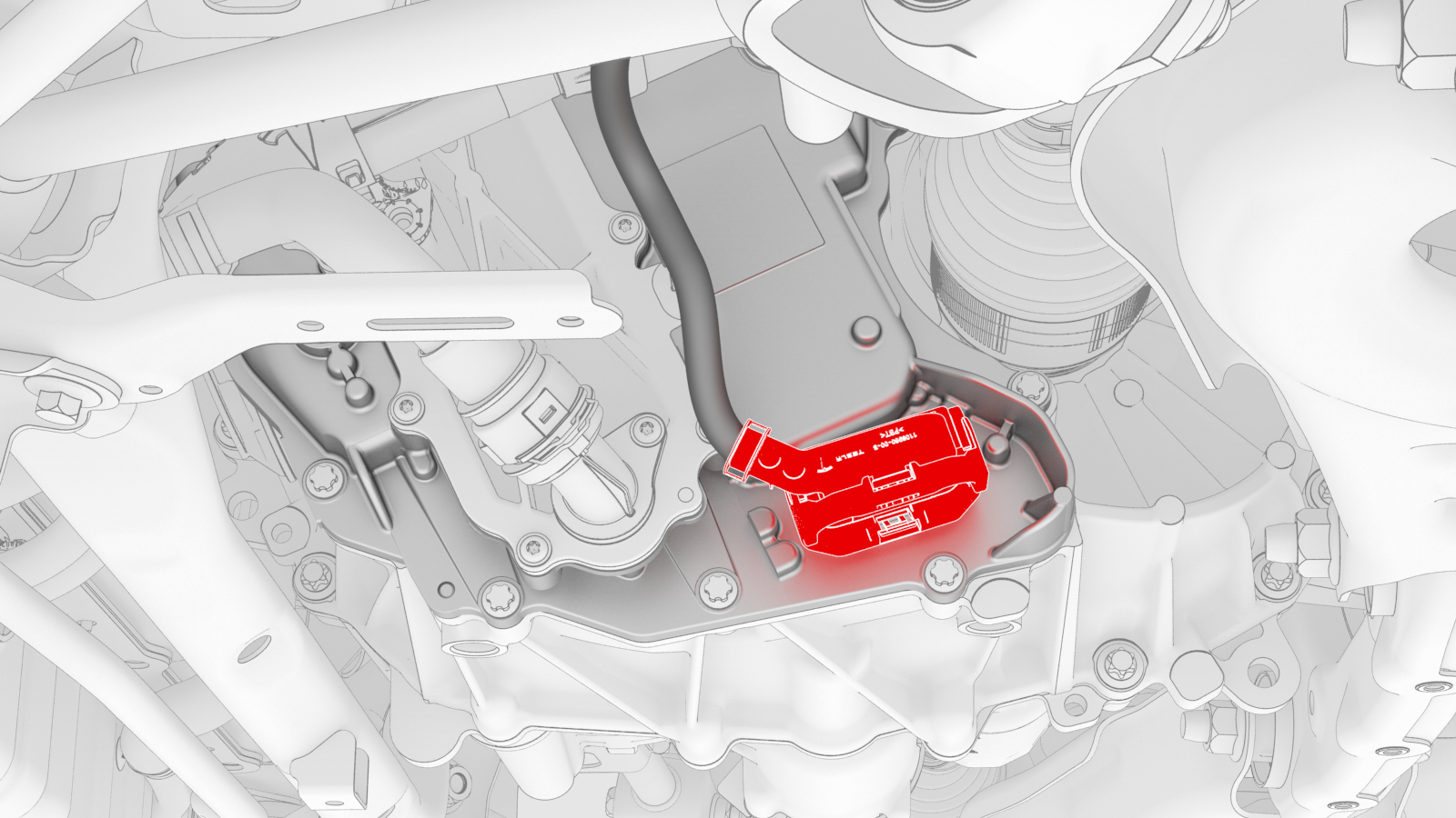
Release the clip that attaches the low voltage electrical harness to the inverter.
-
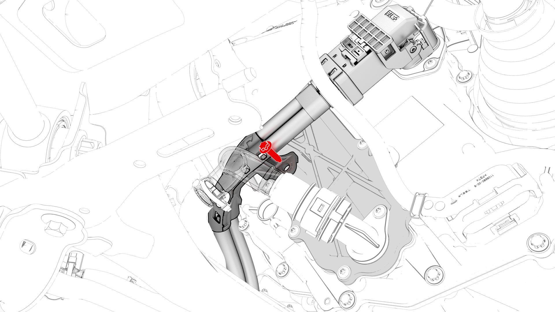
Remove the bolt that attaches the HV electrical harness to the inverter.
-
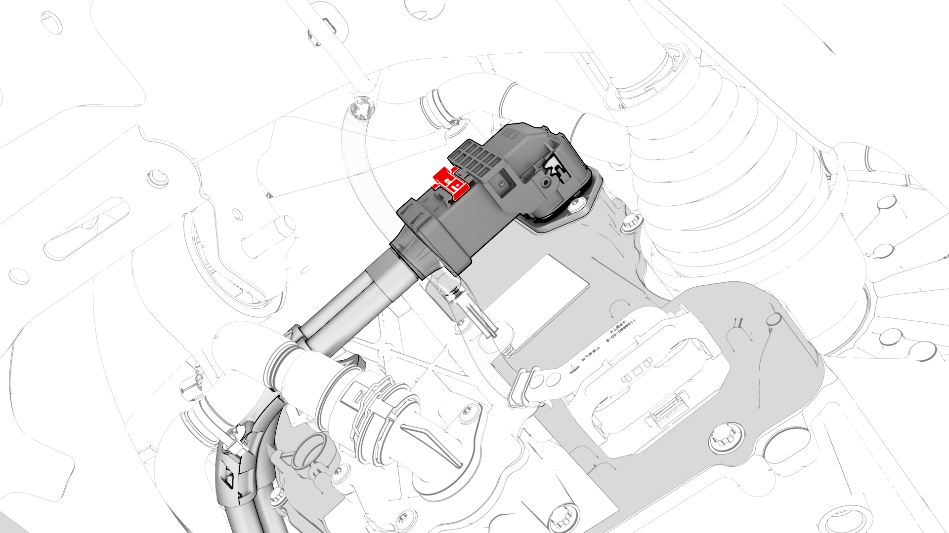
Slide the release to unlock the HV electrical harness.
-
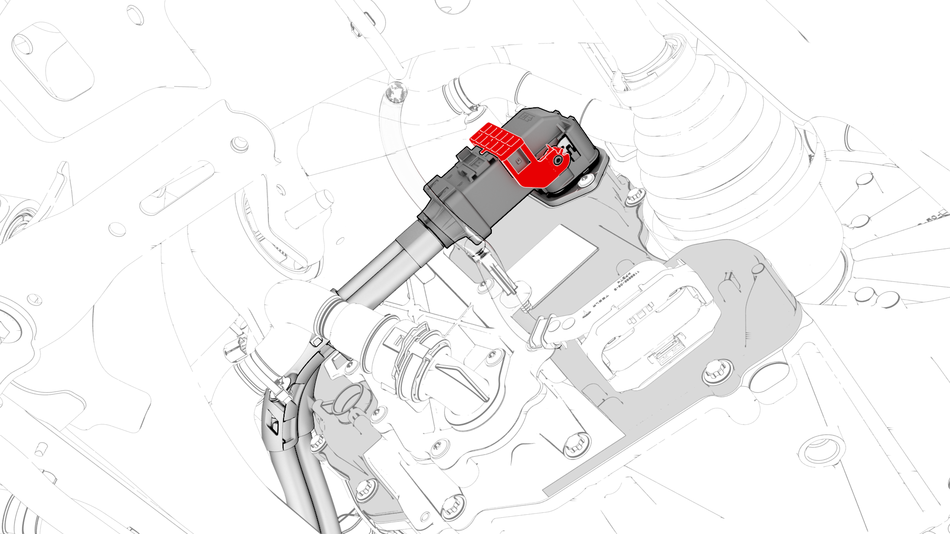
Lift the handle on HV electrical harness, and then disconnect the HV electrical harness from the inverter connector.
-
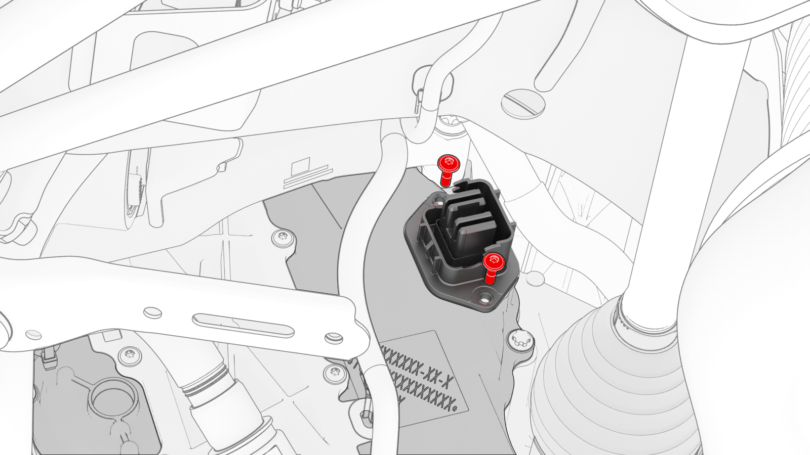
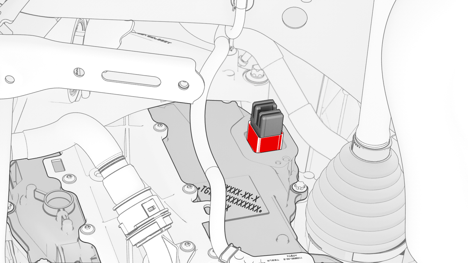
Remove and discard the bolts that attach the HV header to the inverter.
-
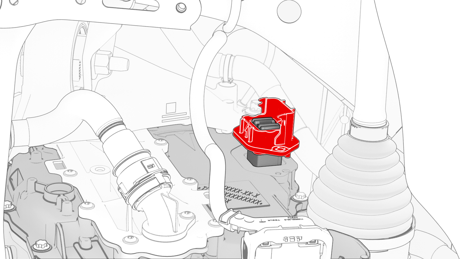
Insert the extractor tool into the HV header, push the tool handle in, and pull on the header to remove it from the inverter.
-
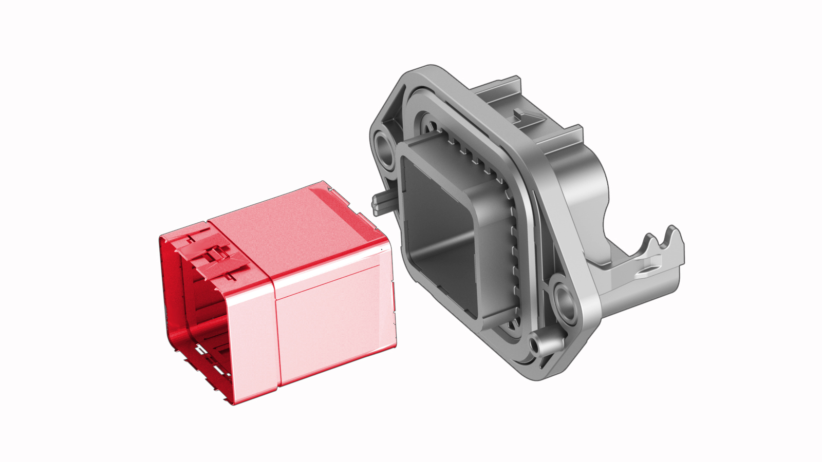
Release the clips (x6) that attach the retainer to the inverter, and then remove and discard the retainer from the inverter.
| 1 | Perform the vehicle electrical isolation procedure. See Vehicle Electrical Isolation Procedure. | ||
| 2 | Remove the mid aero shield panel. See Panel - Aero Shield - Mid (Remove and Replace). | ||
| 3 | Release the clip that attaches the rear drive unit inlet hose to the rear drive unit inverter. | |
| 4 | Disconnect the low voltage electrical harness from the inverter connector. | |
| 5 | Release the clip that attaches the low voltage electrical harness to the inverter. | |
| 6 | Remove the bolt that attaches the HV electrical harness to the inverter. | |
| 7 | Slide the release to unlock the HV electrical harness. | |
| 8 | Lift the handle on HV electrical harness, and then disconnect the HV electrical harness from the inverter connector. | |
| 9 | Remove and discard the bolts that attach the HV header to the inverter. | |
| 10 | Insert the extractor tool into the HV header, push the tool handle in, and pull on the header to remove it from the inverter. | |
| 11 | Release the clips (x6) that attach the retainer to the inverter, and then remove and discard the retainer from the inverter. |
Install
-
Install a new retainer into the header, and then fasten the clips (x6) that attach the retainer to the header.
-
Install the HV header onto the inverter.
Note: Push, pull, and push on the header to make sure it is fully seated.
-
Install the new bolts (x2) that attach the HV header to the inverter.
 Torque 6 Nm
 -
Attach the HV connector lever lock onto the back of the HV electrical harness.
-
Firmly connect the HV electrical harness to the inverter connector.
 Caution:Make sure that the harness fits the connector squarely and tightly.
 -
While pressing the harness to the connector, fully lower the handle.
-
Slide the release to lock the HV electrical harness.
-
Install the bolt that attaches the HV electrical harness to the inverter.
 Torque 6 Nm
 -
Fasten the clip that attaches the low voltage electrical harness to the inverter.
-
Connect the low voltage electrical harness to the inverter connector.
-
Fasten the clip that attaches the rear drive unit inlet hose to the rear drive unit inverter.
| 1 | Install a new retainer into the header, and then fasten the clips (x6) that attach the retainer to the header. | |
| 2 | Install the HV header onto the inverter. Note: Push, pull, and push on the header to make sure it is fully seated.
| |
| 3 | Install the new bolts (x2) that attach the HV header to the inverter. Torque 6 Nm | |
| 4 | Perform an inverter air leak test. See Inverter Air Leak Test. | ||
| 5 | Fully raise the handle on the rear drive unit HV electrical harness. | ||
| 6 | Attach the HV connector lever lock onto the back of the HV electrical harness. | |
| 7 | Firmly connect the HV electrical harness to the inverter connector. Caution: Make sure that the harness fits the connector squarely and tightly.
| ||
| 8 | While pressing the harness to the connector, remove the HV connector lever lock. | ||
| 9 | While pressing the harness to the connector, fully lower the handle. | |
| 10 | Slide the release to lock the HV electrical harness. | |
| 11 | Install the bolt that attaches the HV electrical harness to the inverter. Torque 6 Nm | |
| 12 | Fasten the clip that attaches the low voltage electrical harness to the inverter. | |
| 13 | Connect the low voltage electrical harness to the inverter connector. | |
| 14 | Fasten the clip that attaches the rear drive unit inlet hose to the rear drive unit inverter. | |
| 15 | Remove the mid aero shield panel. See Panel - Aero Shield - Mid (Remove and Replace). | ||
| 16 | Perform a penthouse air leak test. See Penthouse Air Leak Test. | ||
| 17 | Connect 12V power. See 12V Power (Disconnect and Connect). |