Charge Port Voltage Check
Correction code 4401210044012100
- 1076921-00-B Insulation Multimeter, Fluke 1507 (NA)
- 1076921-00-A Insulation Multimeter, Fluke 1587 (EMEA)
- 1076921-01-B Insulation Multimeter, Fluke 1508 (APAC)
- 1130480-00-A Test Probes, Slim, Fluke TP38
SPECIAL TOOLS
Insulation Multimeter, Fluke 1507 (NA) (1076921-00-B) |
Insulation Multimeter, Fluke 1587 (EMEA) (1076921-00-A) |
Insulation Multimeter, Fluke 1508 (APAC) (1076921-01-B) |
Test Probes, Slim, Fluke TP38 (1130480-00-A) |
 Warning: This procedure verifies that high voltage power is no longer available to the charge port. Perform this procedure before servicing any part of the charge port assembly.Warning: Remove all jewelry (watches, bracelets, rings, necklaces, earrings, ID tags, piercings, etc.) from your person, and all objects (keys, coins, pens, pencils, tools, fasteners, etc.) from your pockets before performing any procedure that exposes you to high voltage.Warning: If corrective eyewear is necessary to safely perform any procedure, make sure that the eyewear is securely restrained to the head and cannot fall off.Warning:
Only technicians who have been trained in High Voltage Awareness are permitted to perform this procedure. Proper personal protective equipment (PPE) and insulating HV gloves with a minimum rating of class 0 (1000V) must be worn at all times a high voltage cable, busbar, or fitting is handled. Refer to Tech Note TN-15-92-003, "High Voltage Awareness Care Points" for additional safety information.
Warning: Make sure that the insulation meter and leads are capable of handling at least 500V DC.Procedure (Single-Phase)
-
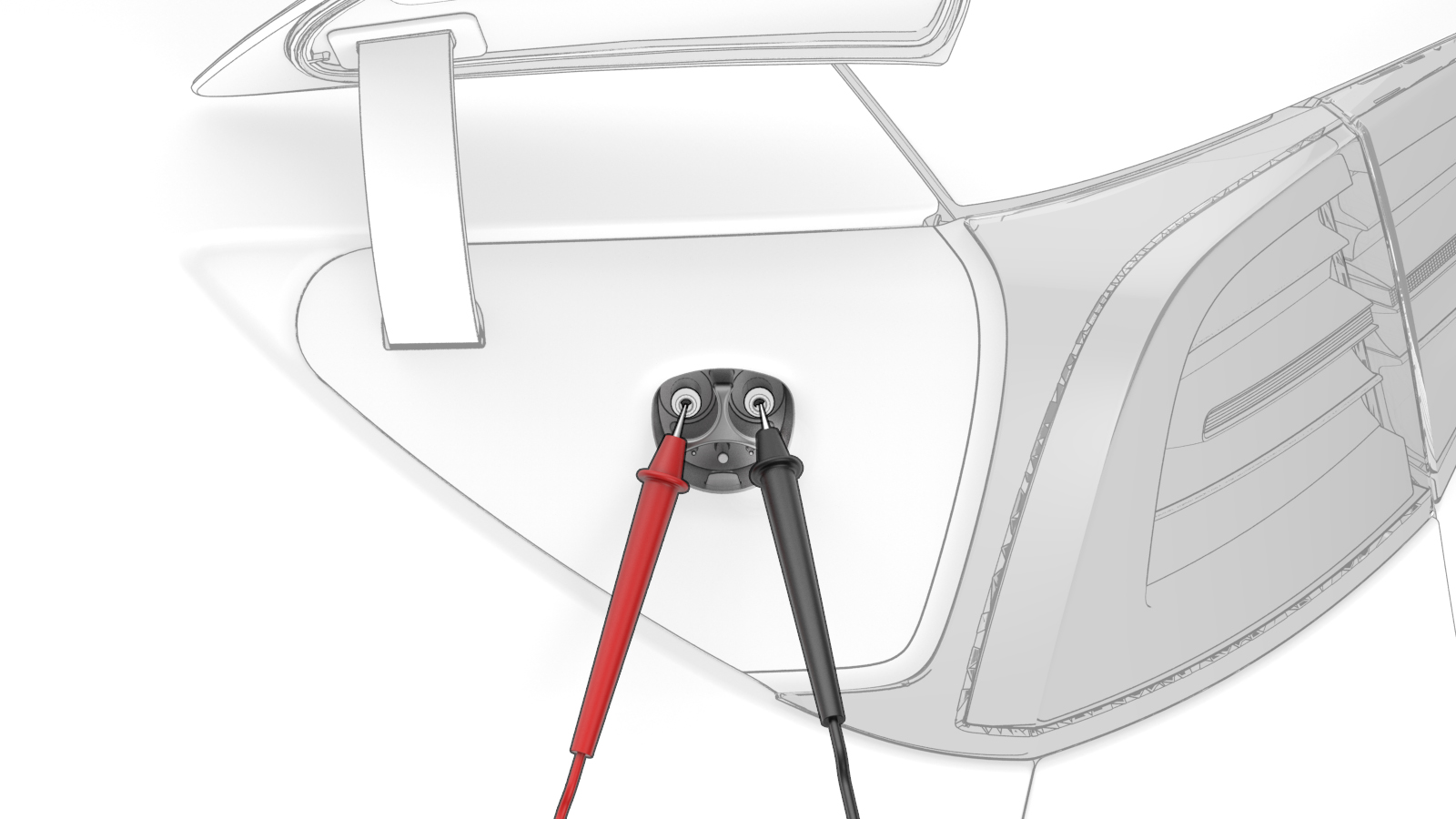
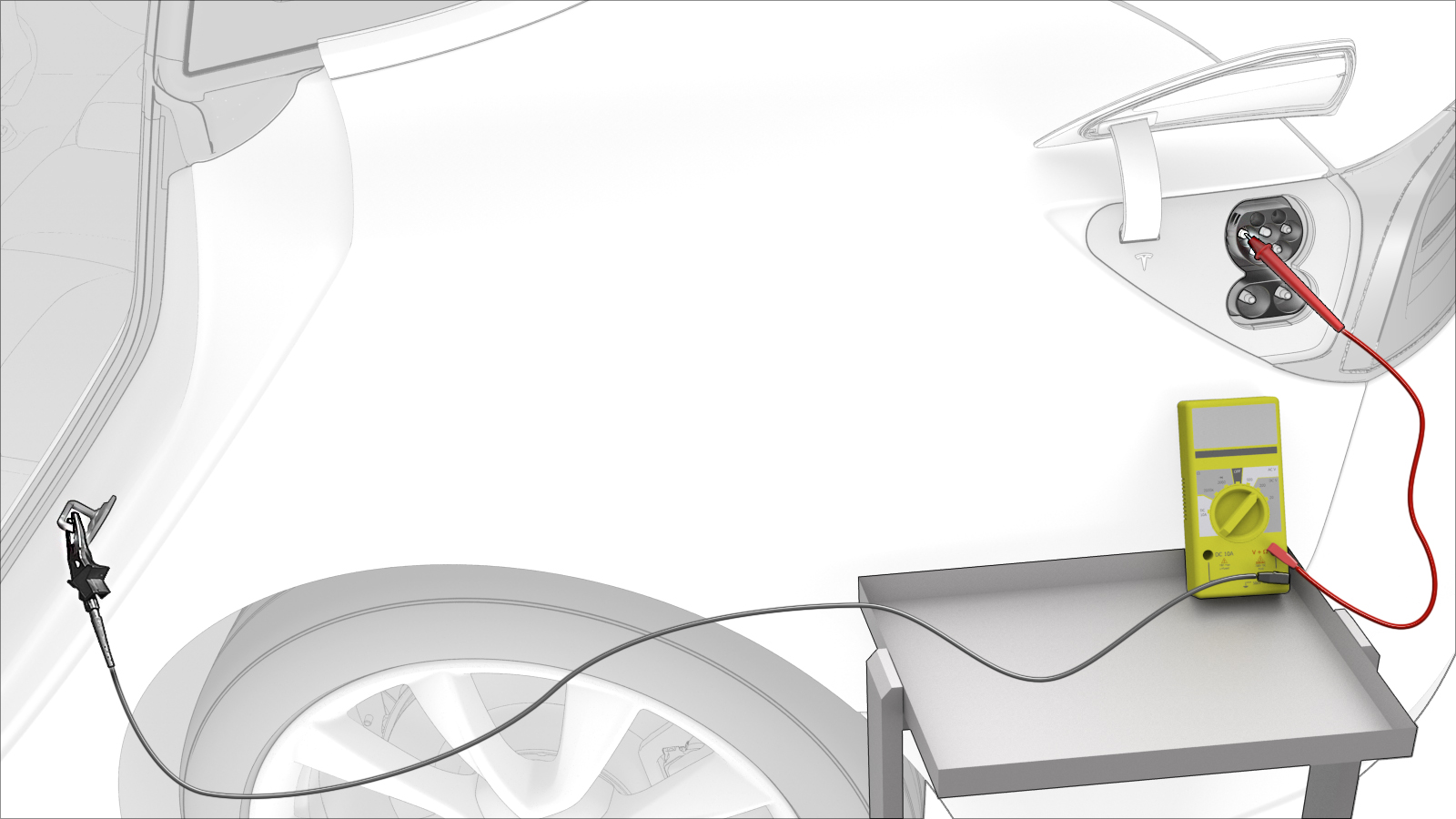
Use the insulation multimeter with slim test probes to check voltages at charge port terminals B+ and B-.
 Warning: If the voltage reading is greater than 10V, the HV battery contactors are closed or welded. Stop this procedure and escalate a Toolbox session, as appropriate.
 -
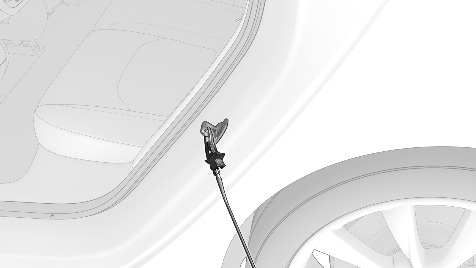
Attach the insulation multimeter ground connector to the LH rear door latch striker.
-
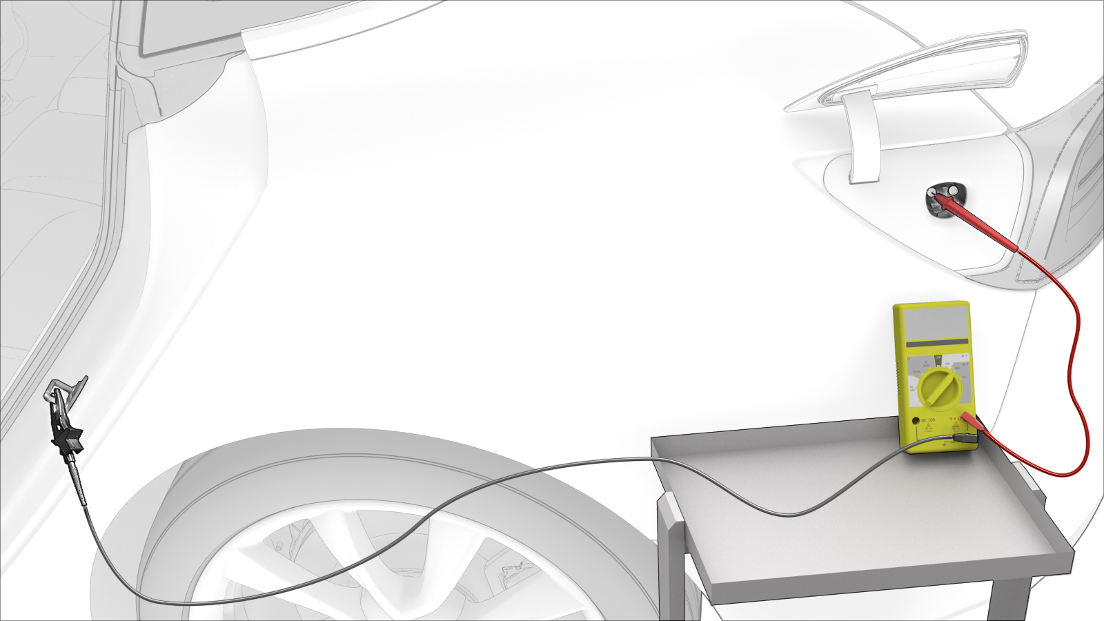
Use the insulation multimeter to check voltages at B+ and ground.
 Warning: If the voltage reading is greater than 10V, the HV battery contactors are closed or welded. Stop this procedure and escalate a Toolbox session, as appropriate.
 -
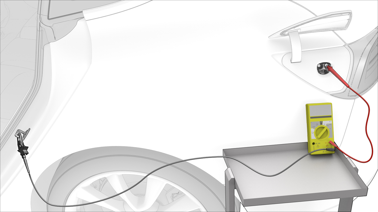
Use the insulation multimeter to check voltages at B- and ground.
 Warning: If the voltage reading is greater than 10V, the HV battery contactors are closed or welded. Stop this procedure and escalate a Toolbox session, as appropriate.
| 1 | Open the charge port door. | ||
| 2 | Disconnect 12V power. See 12V Power (Disconnect and Connect). | ||
| 3 | Set the insulation multimeter to measure DC voltage. | ||
| 4 | Put on safety glasses, High Voltage (HV) insulating gloves, and leather glove protectors. | ||
| 5 | Use the insulation multimeter with slim test probes to check voltages at charge port terminals B+ and B-.Warning: If the voltage reading is greater than 10V, the HV battery contactors are closed or welded. Stop this procedure and escalate a Toolbox session, as appropriate. | |
| 6 | Attach the insulation multimeter ground connector to the LH rear door latch striker. | |
| 7 | Use the insulation multimeter to check voltages at B+ and ground.Warning: If the voltage reading is greater than 10V, the HV battery contactors are closed or welded. Stop this procedure and escalate a Toolbox session, as appropriate. | |
| 8 | Use the insulation multimeter to check voltages at B- and ground.Warning: If the voltage reading is greater than 10V, the HV battery contactors are closed or welded. Stop this procedure and escalate a Toolbox session, as appropriate. | |
| 9 | If all previous voltage readings were less than 10V, return to the procedure that specified the charge port voltage check. |
Procedure (Three-Phase) (Except China)
-
Set the insulation multimeter to measure the DC voltage across the 12V auxiliary battery terminals.
 Caution:If the voltage across the 12V auxiliary battery terminals is less than 10 volts or greater than 14 volts, the multimeter is not measuring reliably and must not be used. Use only a fully functional multimeter.
 -
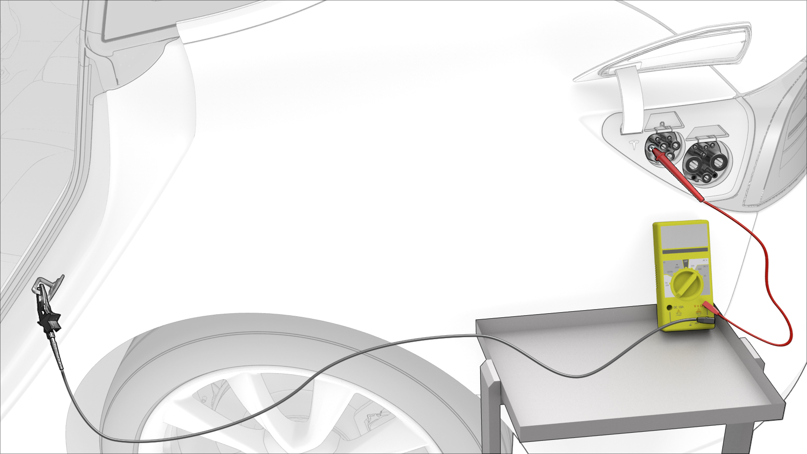
Attach the black negative alligator clip to the LH rear door striker.
-
Touch the red positive slim test probe to each of the lower 4 pin terminals of the charge connector highlighted in this illustration, and read the voltage:
- If a terminal voltage is less than 10V, measure the next terminal, until all are measured.
- If a terminal voltage is 10V or greater, stop this procedure and contact Service Engineering.
Note: Touch the sides of the terminals inside of the pin terminals, not the tips.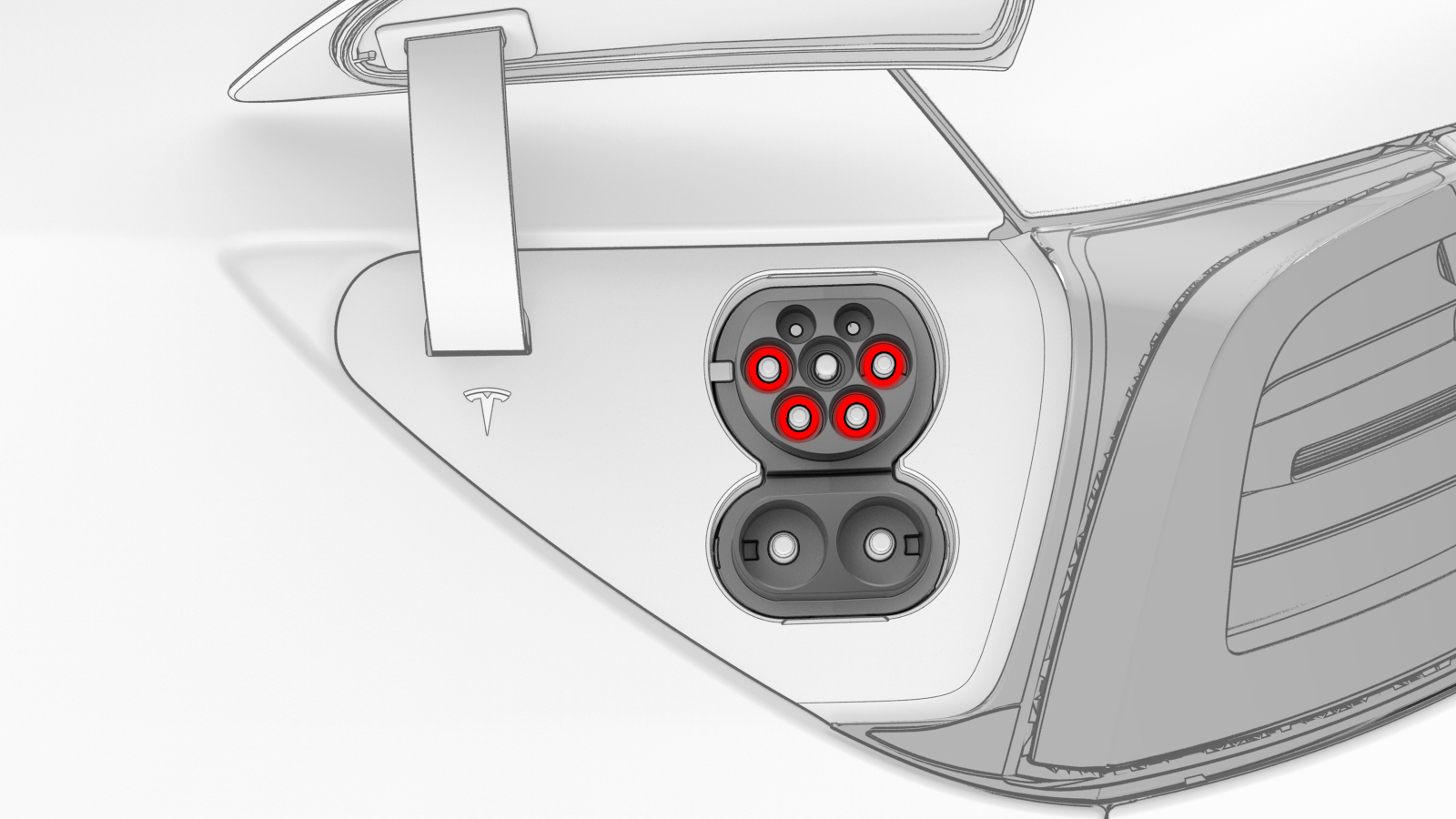
-
Touch the red positive slim test probe to each of the terminals of the DC connector highlighted in this illustration, and read the voltage:
- If a terminal voltage is less than 10V, measure the other terminal.
- If a terminal voltage is 10V or greater, stop this procedure and contact Service Engineering.
Note: Touch the sides of the terminals inside of the pin terminals, not the tips.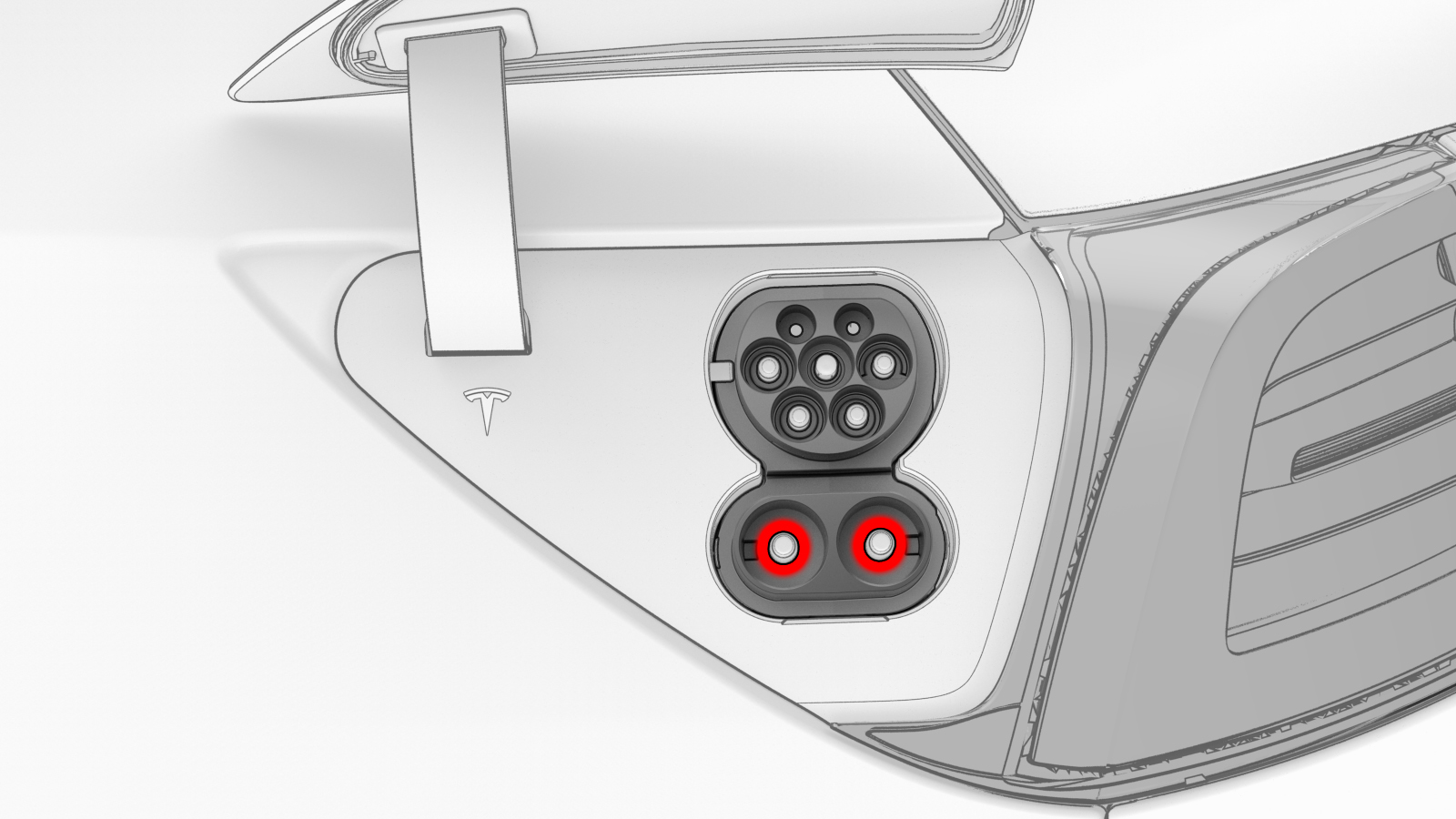
| 1 | Open the charge port door. | ||
| 2 | Disconnect 12V power. See 12V Power (Disconnect and Connect). | ||
| 3 | Set the insulation multimeter to measure the DC voltage across the 12V auxiliary battery terminals. Caution: If the voltage across the 12V auxiliary battery terminals is less than 10 volts or greater than 14 volts, the multimeter is not measuring reliably and must not be used. Use only a fully functional multimeter.
| ||
| 4 | Remove all loose articles and jewelry from your person. | ||
| 5 | Put on safety glasses, High Voltage (HV) insulating gloves, and leather glove protectors. | ||
| 6 | Prepare the insulation multimeter with slim test probes and alligator clips. | ||
| 7 | Attach the black negative alligator clip to the LH rear door striker. | |
| 8 | Set the insulation multimeter to DC voltage. | ||
| 9 | Touch the red positive slim test probe to each of the lower 4 pin terminals of the charge connector highlighted in this illustration, and read the voltage:
Note: Touch the sides of the terminals inside of the pin terminals, not the tips.
| |
| 10 | Touch the red positive slim test probe to each of the terminals of the DC connector highlighted in this illustration, and read the voltage:
Note: Touch the sides of the terminals inside of the pin terminals, not the tips.
| |
| 11 | If all previous voltage readings were less than 10V, return to the procedure that specified the charge port voltage check. |
Procedure (Three-Phase) (China)
-
Set the insulation multimeter to measure the DC voltage across the 12V auxiliary battery terminals.
Caution:If the voltage across the 12V auxiliary battery terminals is less than 10 volts or greater than 14 volts, the multimeter is not measuring reliably and must not be used. Use only a fully functional multimeter.
-
Attach the black negative alligator clip to the LH rear door striker.
-
Touch the red positive slim test probe to each of the lower 4 pin terminals of the charge connector highlighted in this illustration, and read the voltage:
- If a terminal voltage is less than 10V, measure the next terminal, until all are measured.
- If a terminal voltage is 10V or greater, stop this procedure and contact Service Engineering.
Note: Touch the sides of the terminals inside of the pin terminals, not the tips.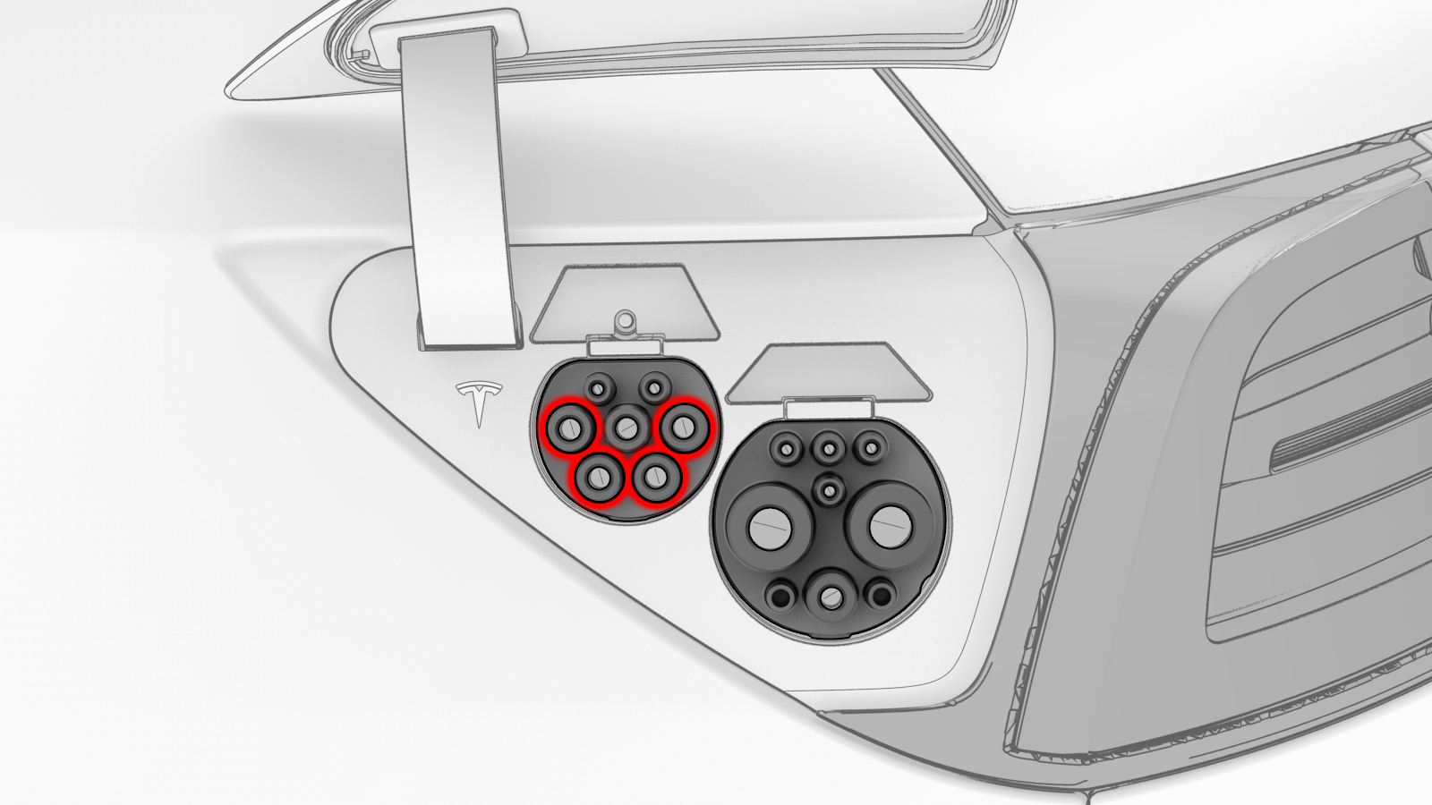
-
Touch the red positive slim test probe to each of the terminals of the DC connector highlighted in this illustration, and read the voltage:
- If a terminal voltage is less than 10V, measure the other terminal.
- If a terminal voltage is 10V or greater, stop this procedure and contact Service Engineering.
Note: Touch the sides of the terminals inside of the pin terminals, not the tips.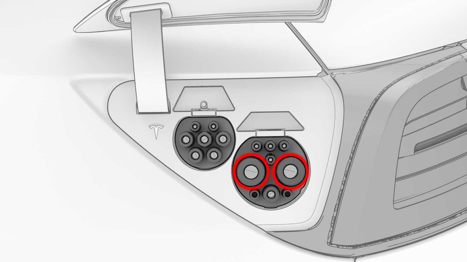
| 1 | Open the charge port door. | ||
| 2 | Disconnect 12V power. See 12V Power (Disconnect and Connect). | ||
| 3 | Set the insulation multimeter to measure the DC voltage across the 12V auxiliary battery terminals. Caution: If the voltage across the 12V auxiliary battery terminals is less than 10 volts or greater than 14 volts, the multimeter is not measuring reliably and must not be used. Use only a fully functional multimeter.
| ||
| 4 | Remove all loose articles and jewelry from your person. | ||
| 5 | Put on safety glasses, High Voltage (HV) insulating gloves, and leather glove protectors. | ||
| 6 | Prepare the insulation multimeter with slim test probes and alligator clips. | ||
| 7 | Attach the black negative alligator clip to the LH rear door striker. | |
| 8 | Set the insulation multimeter to DC voltage. | ||
| 9 | Touch the red positive slim test probe to each of the lower 4 pin terminals of the charge connector highlighted in this illustration, and read the voltage:
Note: Touch the sides of the terminals inside of the pin terminals, not the tips.
| |
| 10 | Touch the red positive slim test probe to each of the terminals of the DC connector highlighted in this illustration, and read the voltage:
Note: Touch the sides of the terminals inside of the pin terminals, not the tips.
| |
| 11 | If all previous voltage readings were less than 10V, return to the procedure that specified the charge port voltage check. |