Inverter - Rear Drive Unit (Remove and Replace)
Correction code 4020060240200602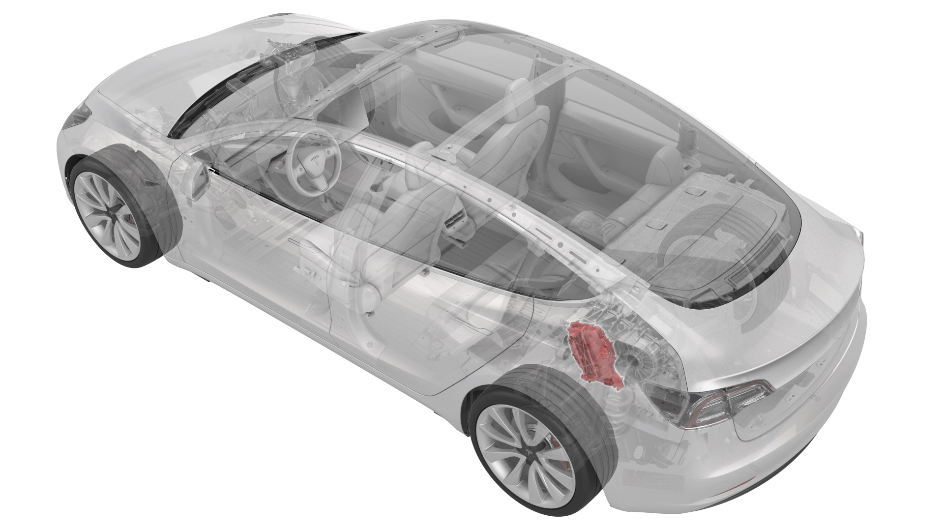
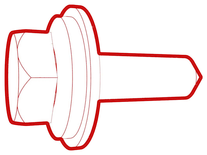
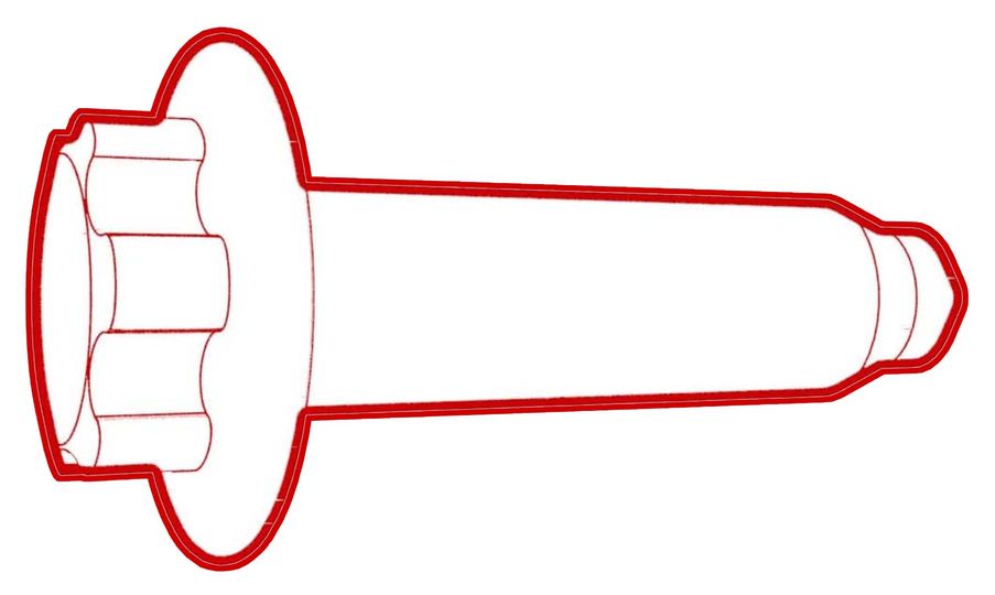
- 1130479-00-A Skt, 3/8in Dr, 10EP Torx Plus External
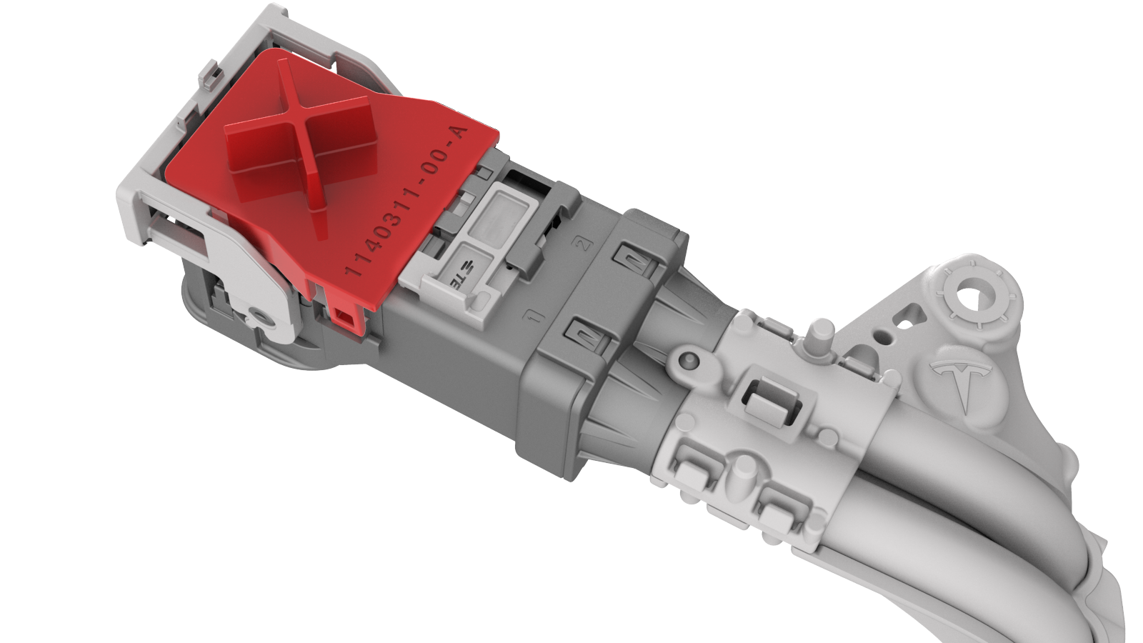
- 1140311-00-ALever Lock, HV Connector, Model 3
SPECIAL TOOLS
Skt, 3/8in Dr, 10EP Torx Plus External (1130479-00-A) |
Lever Lock, HV Connector, Model 3 (1140311-00-A) |
Remove
-
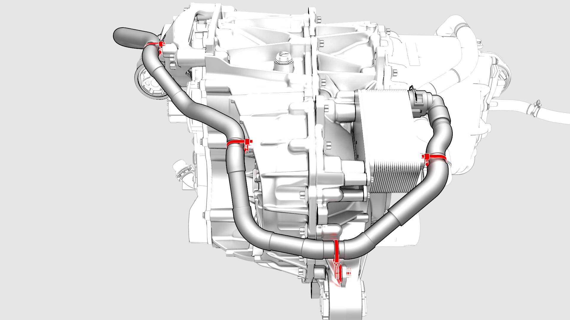
Release the clips that attach the upper cooler hose to the rear drive unit.
-
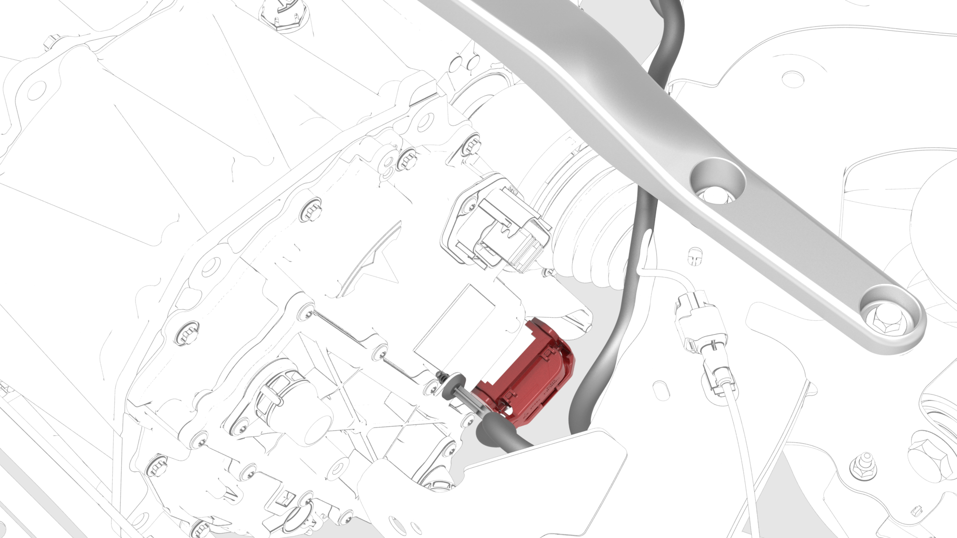
Disconnect the electrical harness from the inverter low voltage connector.
-
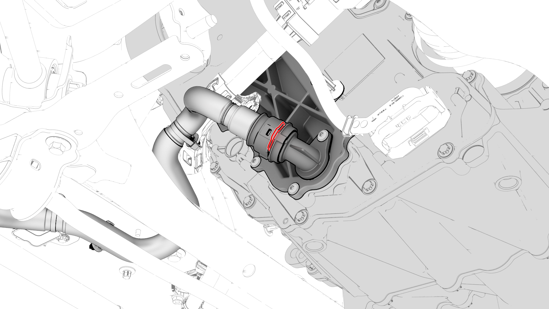
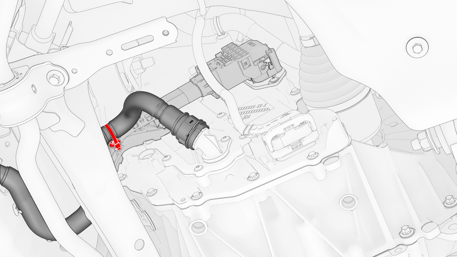
Release the clip, disconnect the rear drive unit inlet hose from the inverter coolant inlet, and then plug the inlet.
-
Release the clip that attaches the rear drive unit inlet hose to the HV harness bracket, and then remove the hose from the rear drive unit.
-
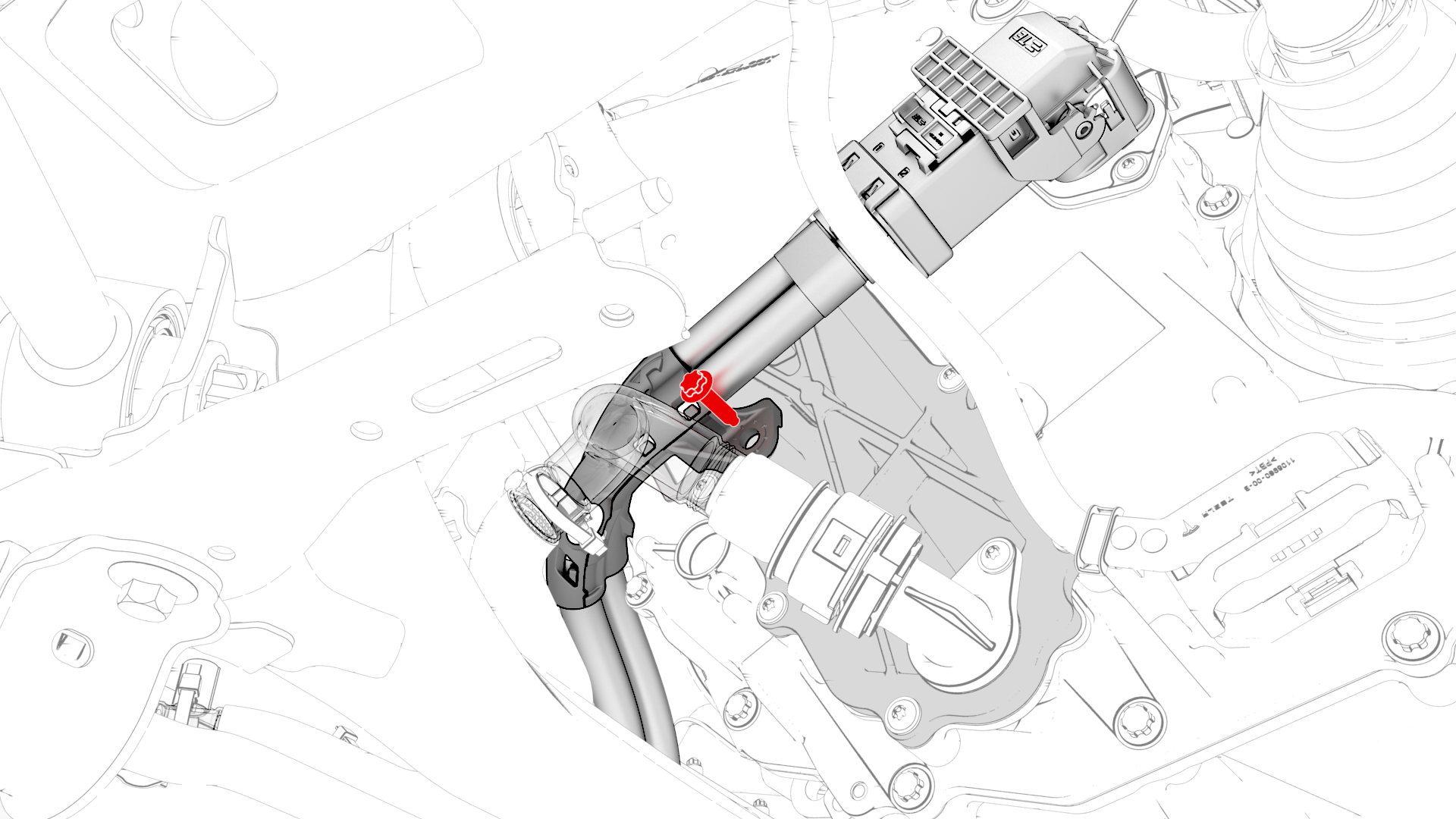
Remove the bolt that attaches the HV harness bracket to the inverter.
-
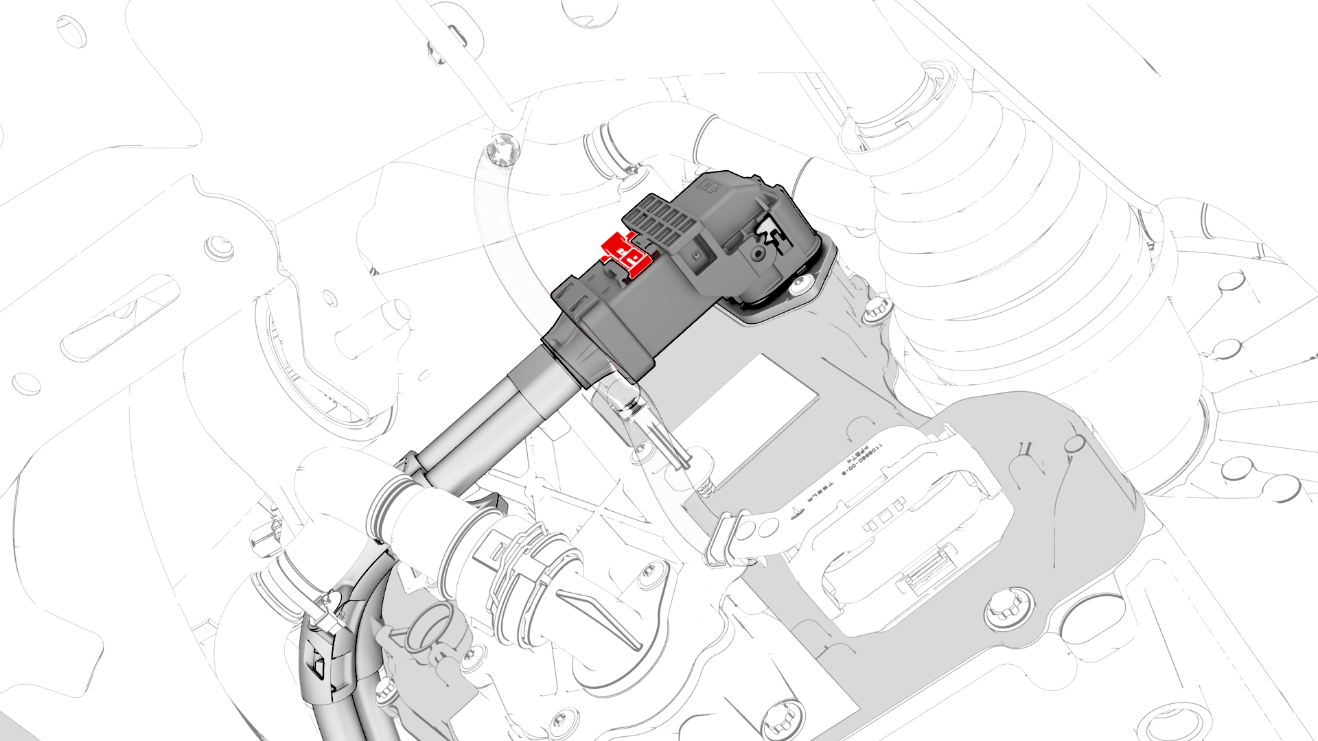
Slide the release to unlock the HV harness connector.
-
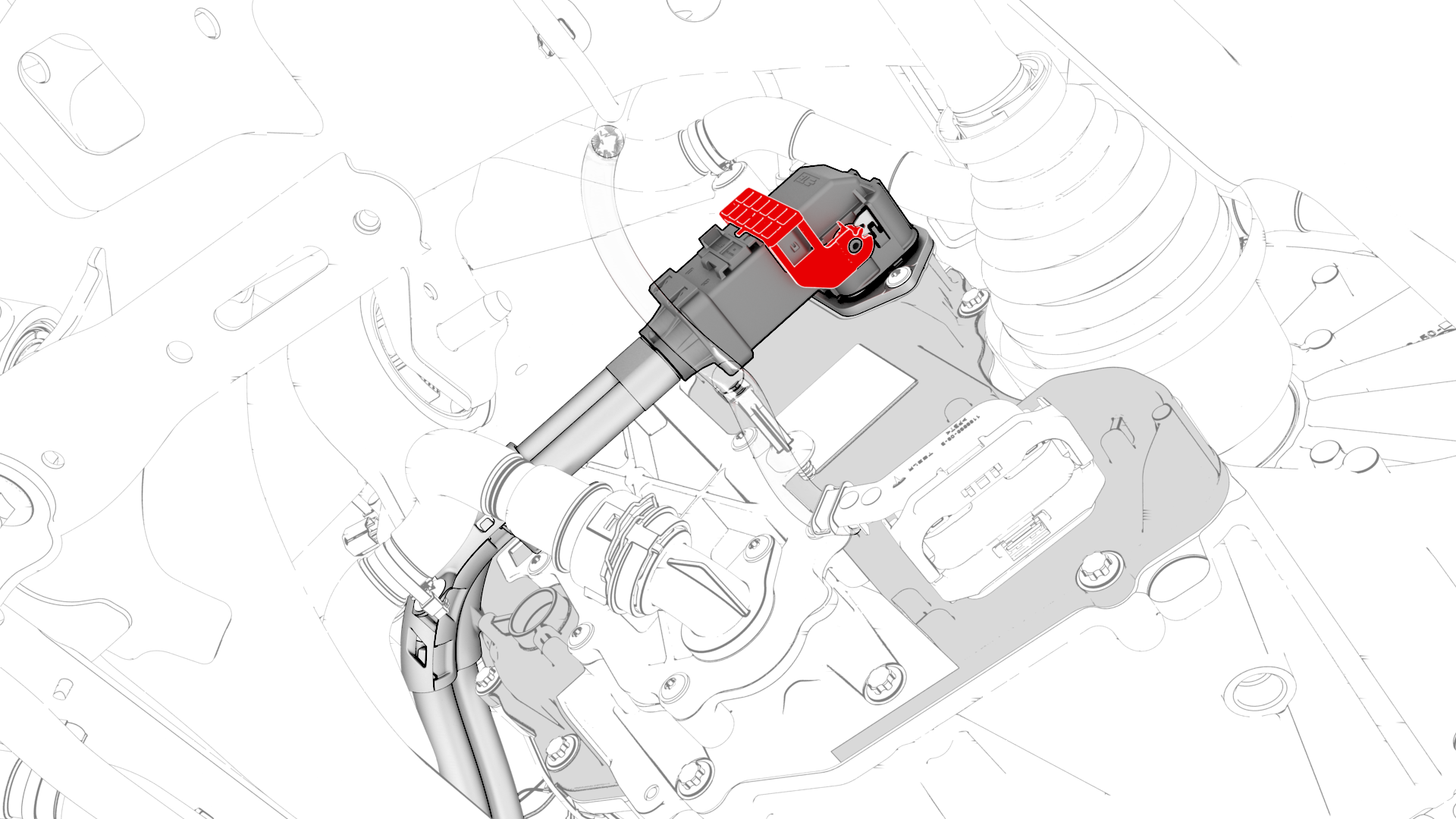
Lift the handle on HV harness connector, disconnect the harness from the inverter connector, and then remove the harness from the rear drive unit.
-
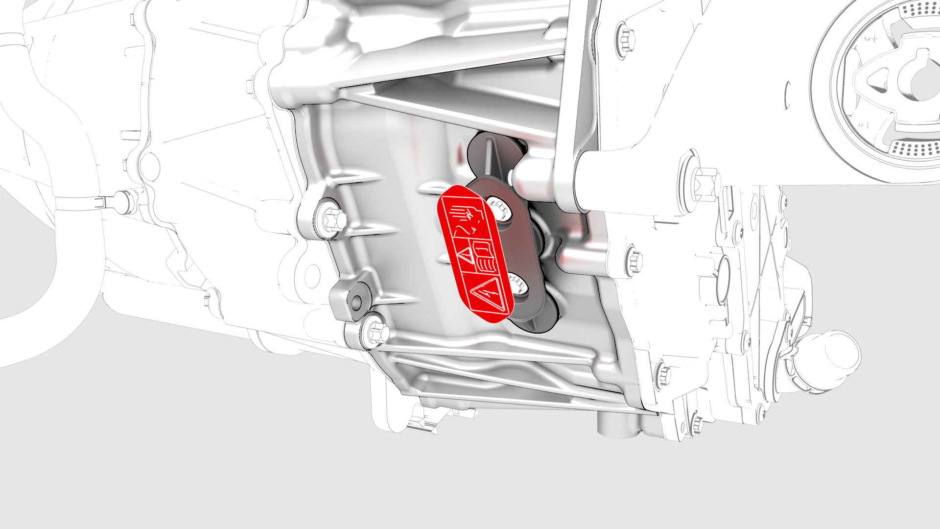
Remove the 3-phase access label.
-
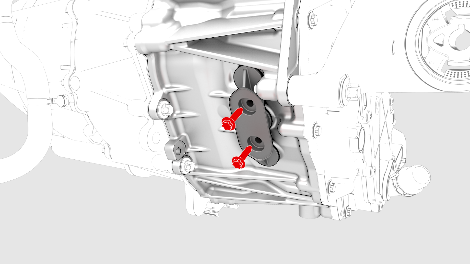
Remove the bolts (x2) that attach the 3-phase access cover to the rear drive unit.
-
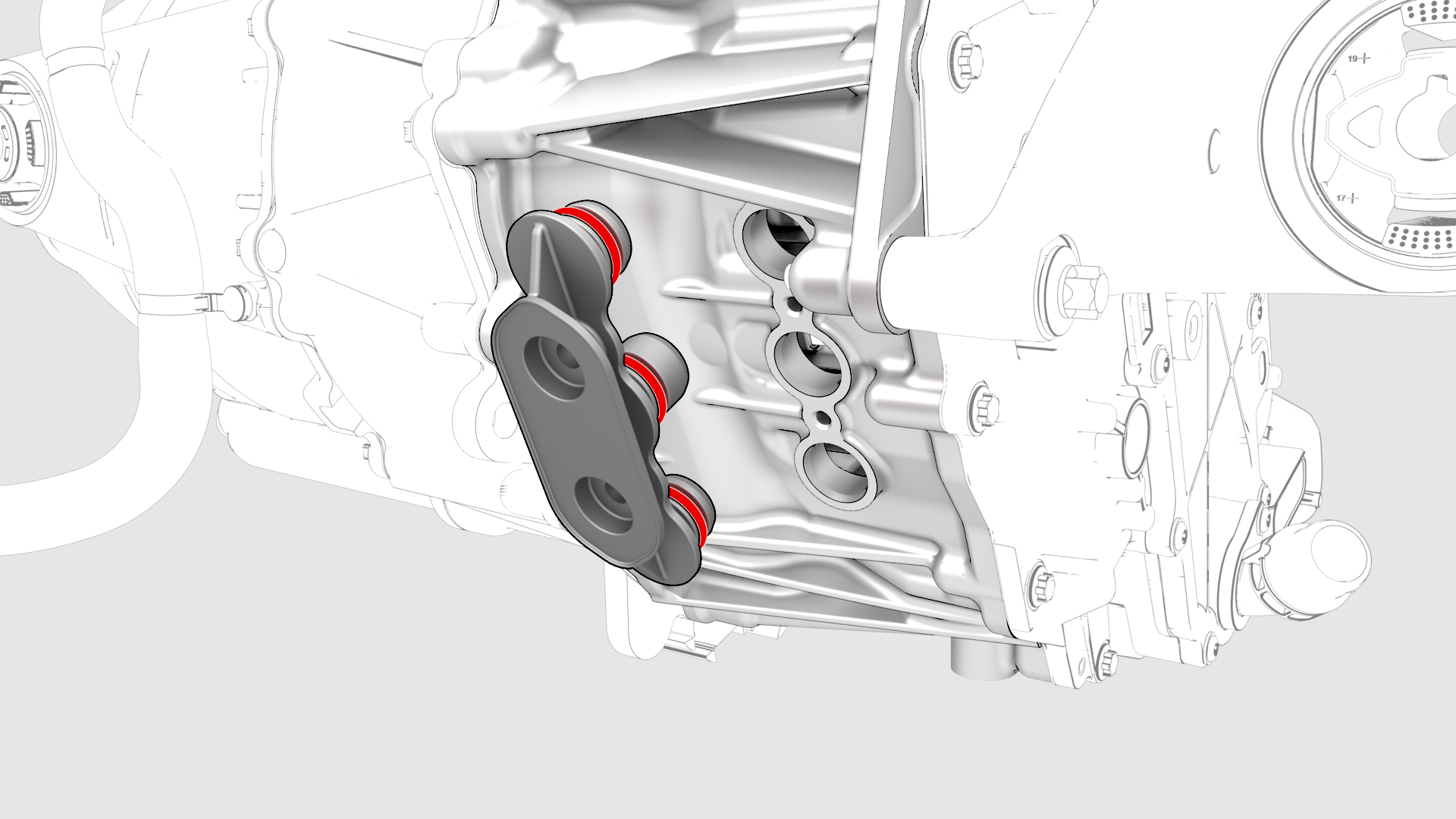
Remove and discard the 3-phase access cover.
-
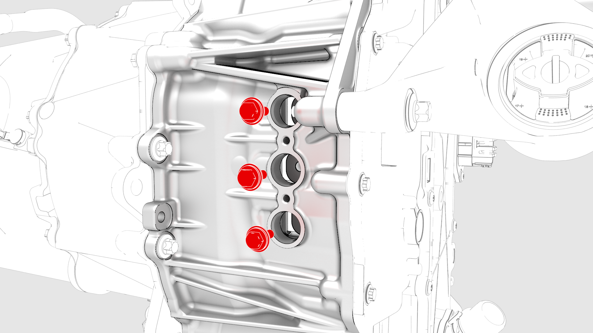
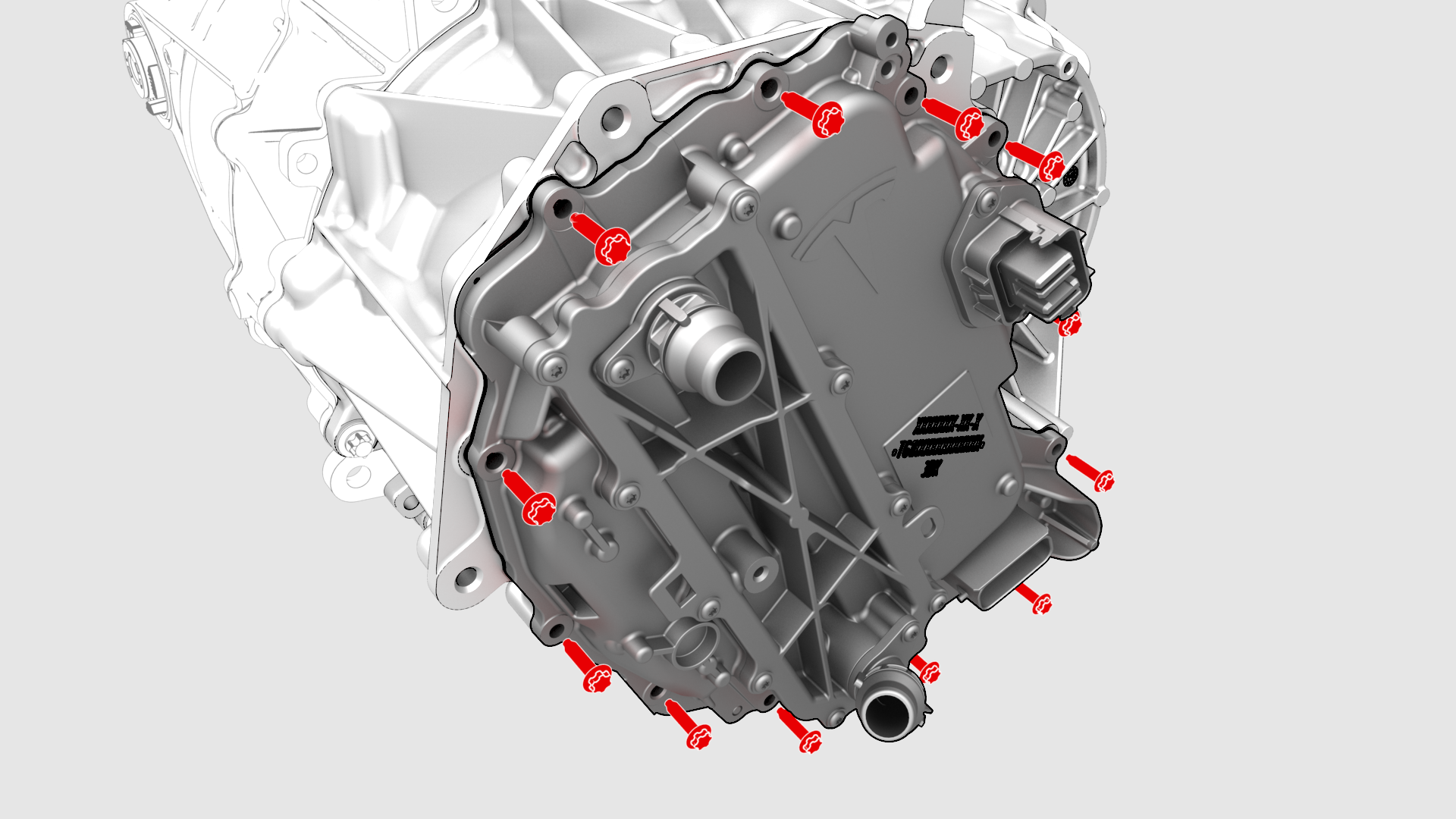
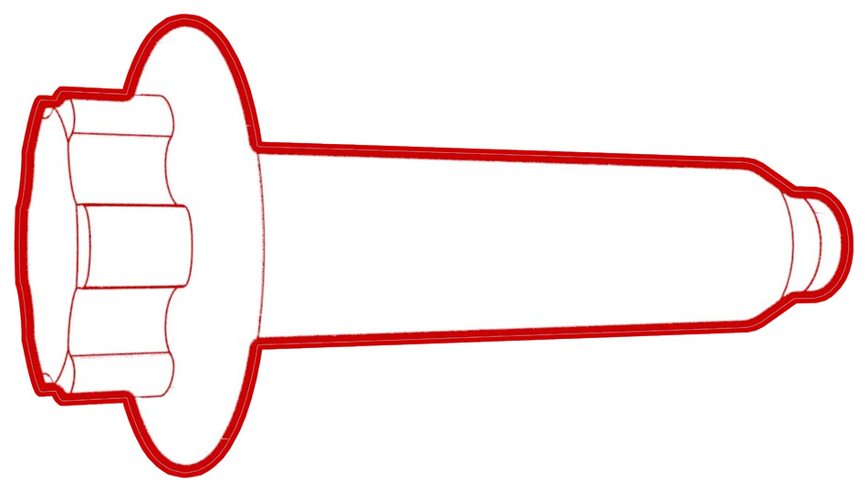
Remove and discard the bolts (x3) that attach the 3-phase terminals to the inverter assembly.
-
Remove and discard the bolts (x12) that attach the inverter to the gearbox assembly.
-
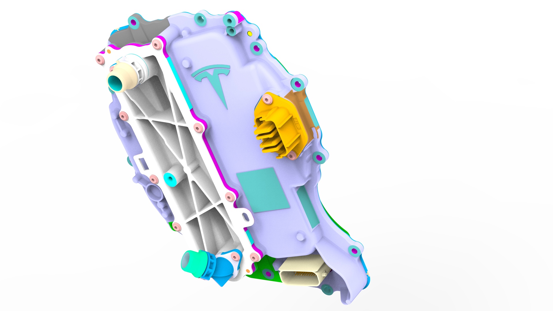
Carefully remove the inverter assembly from the rear drive unit and allow the coolant to drain.
| 1 | Use Toolbox to open the Rear Drive Inverter - Remove and Replace Autodiag, and click Run Network. | ||
| 2 | In the Rear Drive Inverter - Remove and Replace Autodiag, run PROC_DI_X_STORE-DATA-APP to store the application data and run PROC_PM_X_STORE-DATA-BOOT to store the bootloader data. | ||
| 3 | Follow the instructions in the Rear Drive Inverter - Remove and Replace Autodiag to perform the rest of this procedure. | ||
| 4 | Remove the laptop from the vehicle, but do not close Toolbox 3. | ||
| 5 | Remove the rear subframe assembly. See Subframe Assembly - Rear (Remove and Install). | ||
| 6 | Remove the LH rear drive unit mount. See Mount - Rear Drive Unit - LH (Remove and Replace). | ||
| 7 | Release the clips that attach the upper cooler hose to the rear drive unit. | |
| 8 | Disconnect the electrical harness from the inverter low voltage connector. | |
| 9 | Release the clip, disconnect the rear drive unit inlet hose from the inverter coolant inlet, and then plug the inlet. | |
| 10 | Release the clip that attaches the rear drive unit inlet hose to the HV harness bracket, and then remove the hose from the rear drive unit. | |
| 11 | Remove the bolt that attaches the HV harness bracket to the inverter. | |
| 12 | Slide the release to unlock the HV harness connector. | |
| 13 | Lift the handle on HV harness connector, disconnect the harness from the inverter connector, and then remove the harness from the rear drive unit. | |
| 14 | Secure an ESD strap to the inverter housing. | ||
| 15 | Remove the 3-phase access label. | |
| 16 | Remove the bolts (x2) that attach the 3-phase access cover to the rear drive unit. | |
| 17 | Remove and discard the 3-phase access cover. | |
| 18 | Remove and discard the bolts (x3) that attach the 3-phase terminals to the inverter assembly. | |
| 19 | Remove and discard the bolts (x12) that attach the inverter to the gearbox assembly. | |
| 20 | Carefully remove the inverter assembly from the rear drive unit and allow the coolant to drain. | ||
| 21 | Remove and discard the inverter gasket. |
Install
-
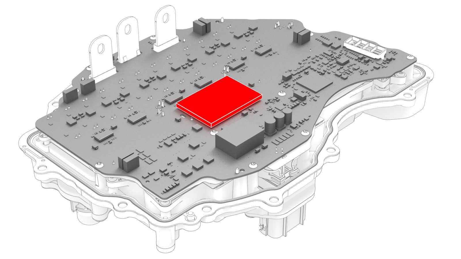
Inspect the condition of the gap pad on the inverter PCB. Replace the gap pad if it does not fulfill these criteria.
- New and undamaged condition.
- Fully covers the discharge resistor array and that no resistors are visible.
- Clean and free of debris.
- Evenly adhered to the inverter PCB.
-
Carefully align the inverter to the 2 pins in the rear drive unit, and then install the inverter to the rear drive unit. Make sure that the 3-phase terminals align during installation.
 Caution:Avoid damage to the printed circuit board of the inverter.
 -
Hand-tighten the new bolts (x12) that attach the inverter to the gearbox assembly.
-
Torque the bolts in the sequence shown.
 Torque 5 Nm +20 deg
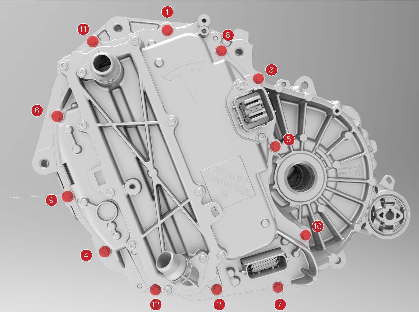
-
Install the new bolts (x3) that attach the 3 phase cable to the inverter assembly.
-
Tighten the bolts to this specification.
 Torque 11.5 Nm
 - Loosen the bolts 180 degrees.
-
Tighten the bolts to this specification.
 Torque 5 Nm +40 deg
-
Tighten the bolts to this specification.
-
Apply a film of ATF-9 fluid to the walls of the gear case bores, and then install the new 3-phase access cover.
-
Install the bolts (x2) that attach the 3-phase access cover to the rear drive unit assembly.
 Torque 7.5 Nm
 -
Apply a new 3-phase access label.
-
Attach the HV connector lever lock onto the back of the HV electrical harness.
-
Firmly connect the HV electrical harness to the inverter connector.
Caution:Make sure that the harness fits the connector squarely and tightly.
-
While pressing the harness to the connector, fully lower the handle.
-
Slide the release to lock the HV electrical harness.
-
Install the bolt that attaches the HV harness bracket to the inverter.
 Torque 6 Nm
 -
Connect the rear drive unit inlet hose to the inverter coolant inlet, and then fasten the clip.
Caution:Perform a push-pull test to verify that the hose is fully seated.
-
Fasten the clip that attaches the rear drive unit inlet hose to the HV harness bracket.
-
Connect the electrical harness to the inverter low voltage connector.
-
Fasten the clips that attach the upper cooler hose to the rear drive unit.
-
Use the Rear Drive Inverter - Remove and Replace Autodiag to:
-
Perform the resolver learn process.
Caution:This process requires the vehicle wheels to be spinning at 55 mph (90 kph) while elevated on a lift.
-
Perform the resolver learn process.
| 1 | Secure the ESD strap to the replacement inverter housing. | ||
| 2 | Inspect the condition of the gap pad on the inverter PCB. Replace the gap pad if it does not fulfill these criteria.
| |
| 3 | Install a new inverter gasket. | ||
| 4 | Use an IPA wipe to clean the HV mating surfaces of the motor and inverter 3-phase terminals. | ||
| 5 | Carefully align the inverter to the 2 pins in the rear drive unit, and then install the inverter to the rear drive unit. Make sure that the 3-phase terminals align during installation. Caution: Avoid damage to the printed circuit board of the inverter.
| ||
| 6 | Hand-tighten the new bolts (x12) that attach the inverter to the gearbox assembly. | |
| 7 | Torque the bolts in the sequence shown. Torque 5 Nm +20 deg | |
| 8 | Install the new bolts (x3) that attach the 3 phase cable to the inverter assembly.
| |
| 9 | Apply a film of ATF-9 fluid to the walls of the gear case bores, and then install the new 3-phase access cover. | |
| 10 | Install the bolts (x2) that attach the 3-phase access cover to the rear drive unit assembly. Torque 7.5 Nm | |
| 11 | Perform an inverter air leak test. See Inverter Air Leak Test. | ||
| 12 | Apply a new 3-phase access label. | |
| 13 | Remove the ESD wrist strap. | ||
| 14 | Fully raise the handle on the rear drive unit HV electrical harness. | ||
| 15 | Attach the HV connector lever lock onto the back of the HV electrical harness. | |
| 16 | Firmly connect the HV electrical harness to the inverter connector. Caution: Make sure that the harness fits the connector squarely and tightly.
| ||
| 17 | While pressing the harness to the connector, remove the HV connector lever lock. | ||
| 18 | While pressing the harness to the connector, fully lower the handle. | |
| 19 | Slide the release to lock the HV electrical harness. | |
| 20 | Install the bolt that attaches the HV harness bracket to the inverter. Torque 6 Nm | |
| 21 | Connect the rear drive unit inlet hose to the inverter coolant inlet, and then fasten the clip. Caution: Perform a push-pull test to verify that the hose is fully seated.
| |
| 22 | Fasten the clip that attaches the rear drive unit inlet hose to the HV harness bracket. | |
| 23 | Connect the electrical harness to the inverter low voltage connector. | |
| 24 | Install the LH rear drive unit mount. See Mount - Rear Drive Unit - LH (Remove and Replace). | ||
| 25 | Fasten the clips that attach the upper cooler hose to the rear drive unit. | |
| 26 | Install the rear subframe assembly. See Subframe Assembly - Rear (Remove and Install). | ||
| 27 | Refill the cooling system. See Powertrain Coolant (Drain and Refill). Note: Perform the refill before the installation of the front RH wheel liner.
| ||
| 28 | Within Toolbox, return to the Rear Drive Inverter - Remove and Replace Autodiag, and run PROC_PM_X_RESTORE-DATA-BOOT to restore the bootloader data and run PROC_PM_X_WRITE-DRIVE-TYPE to configure the Usage ID. | ||
| 29 | Use the Rear Drive Inverter - Remove and Replace Autodiag to:
| ||
| 30 | Perform a four wheel alignment. See Four Wheel Alignment (Check and Adjust). |