Subframe Assembly - Rear (Remove and Replace)
Correction code 3001020230010202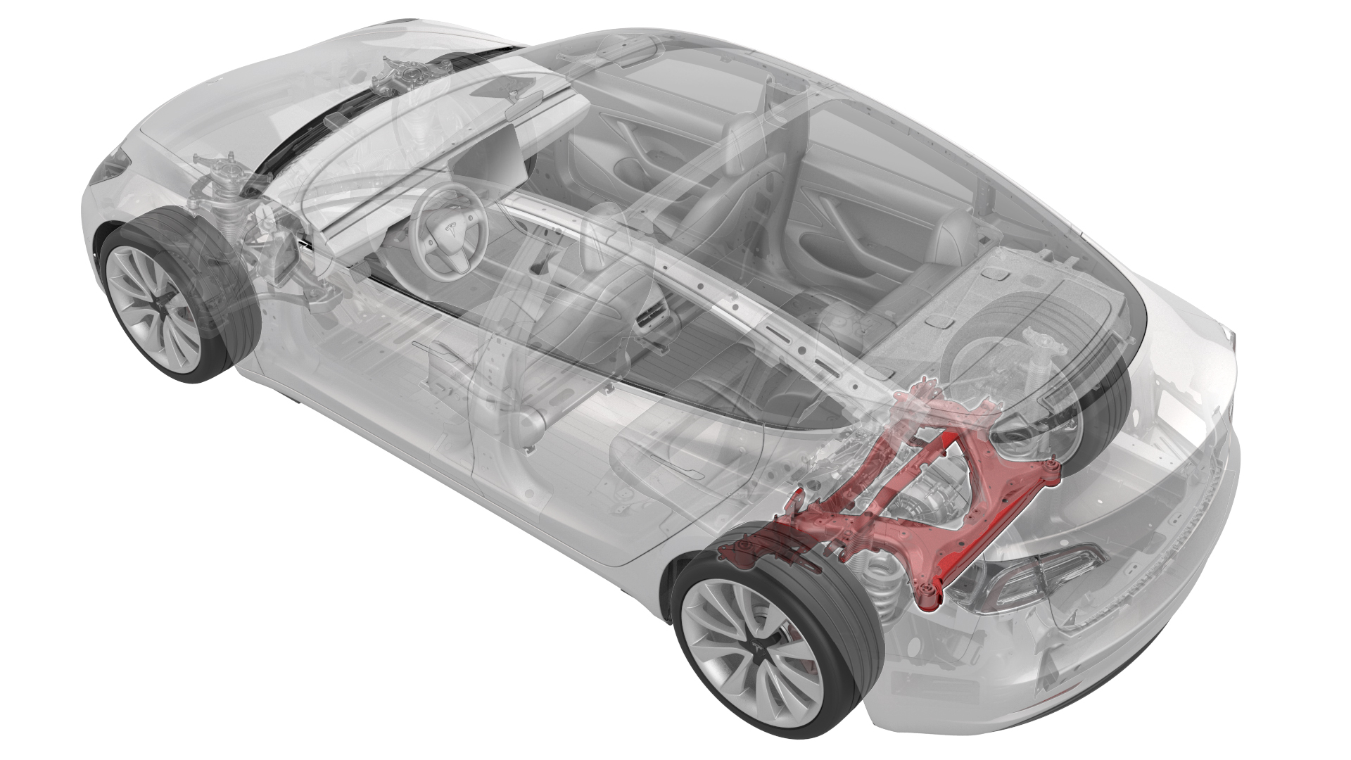
- 1099645-00-BFixture, Subframe, Model 3
- 1130279-00-ALifting Sling, Drive Unit, Model 3 (NA, APAC)
- 1130481-00-AAdapter, Subframe, Body Shop, Model 3
- 1096075-00-ATool, Hub Puller, Hydraulic
- 1133386-00-A Tool, Axle Extraction, Model 3
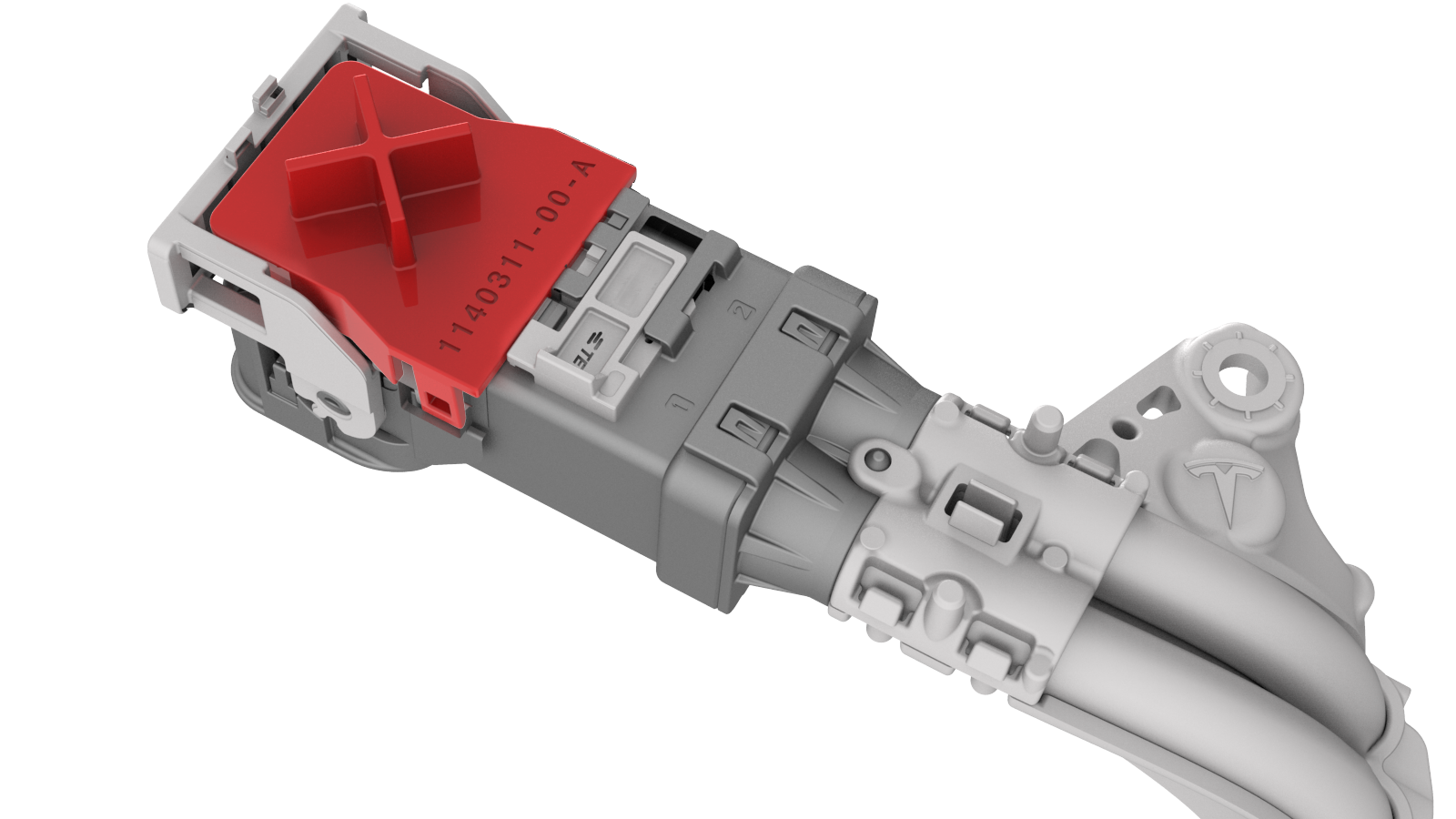
- 1140311-00-ALever Lock, HV Connector, Model 3
SPECIAL TOOLS
Fixture, Subframe, Model 3 (1099645-00-B) |
Lifting Sling, Drive Unit, Model 3 (NA, APAC) (1130279-00-A) |
Adapter, Subframe, Body Shop, Model 3 (1130481-00-A) |
Tool, Hub Puller, Hydraulic (1096075-00-A) |
Tool, Axle Extraction, Model 3 (1133386-00-A) |
Lever Lock, HV Connector, Model 3 (1140311-00-A) |
Remove
-
Disconnect the electrical harness from the inverter low voltage connector.
-
Release the clip that attaches the low voltage electrical harness to the inverter.
-
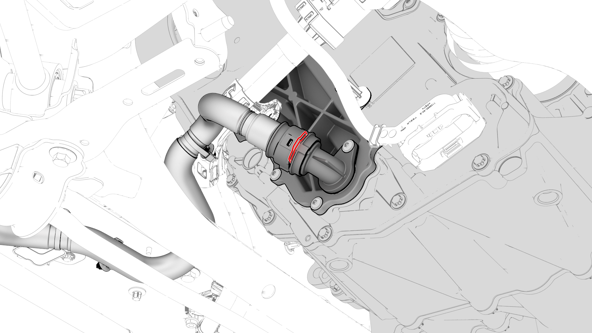
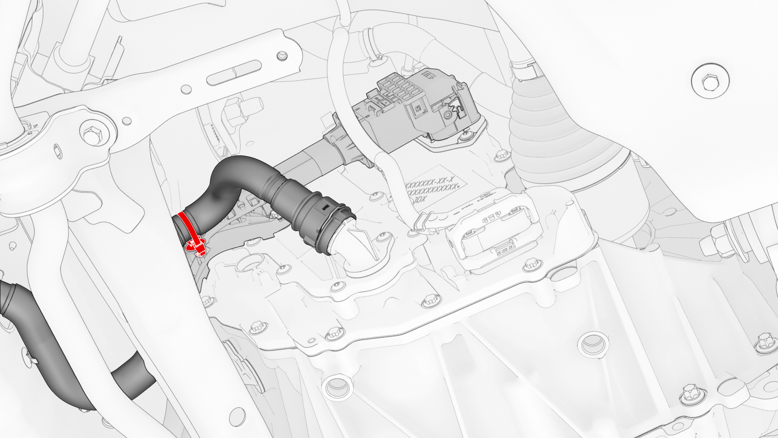
Release the clip, disconnect the rear drive unit inlet hose from the inverter coolant inlet, and then plug the inlet.
-
Release the clip that attaches the rear drive unit inlet hose to the HV harness bracket, and then remove the hose from the rear drive unit.
-
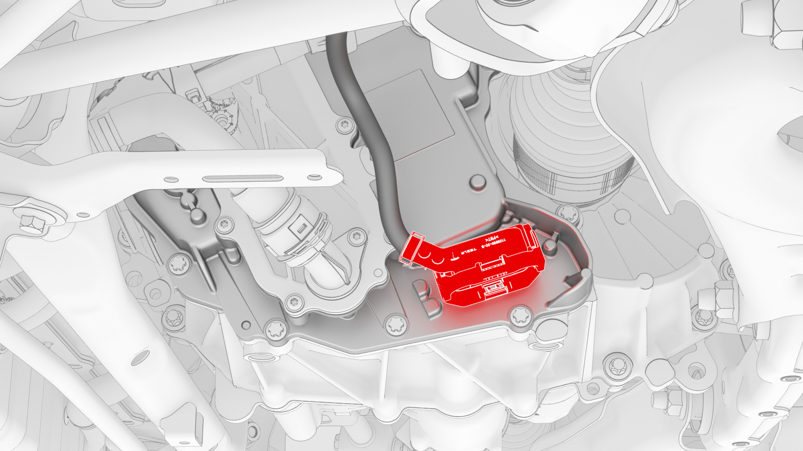
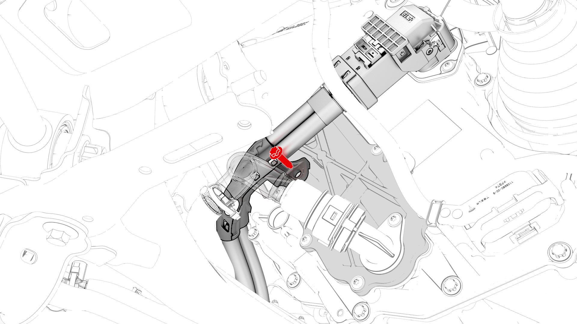
Remove the bolt that attaches the HV harness bracket to the inverter.
-
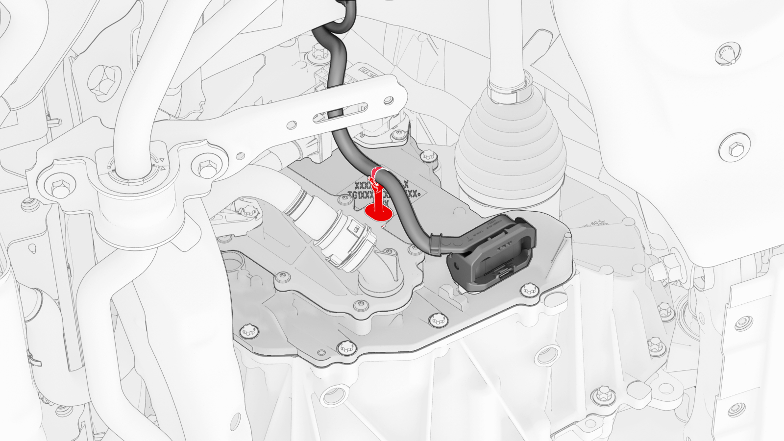
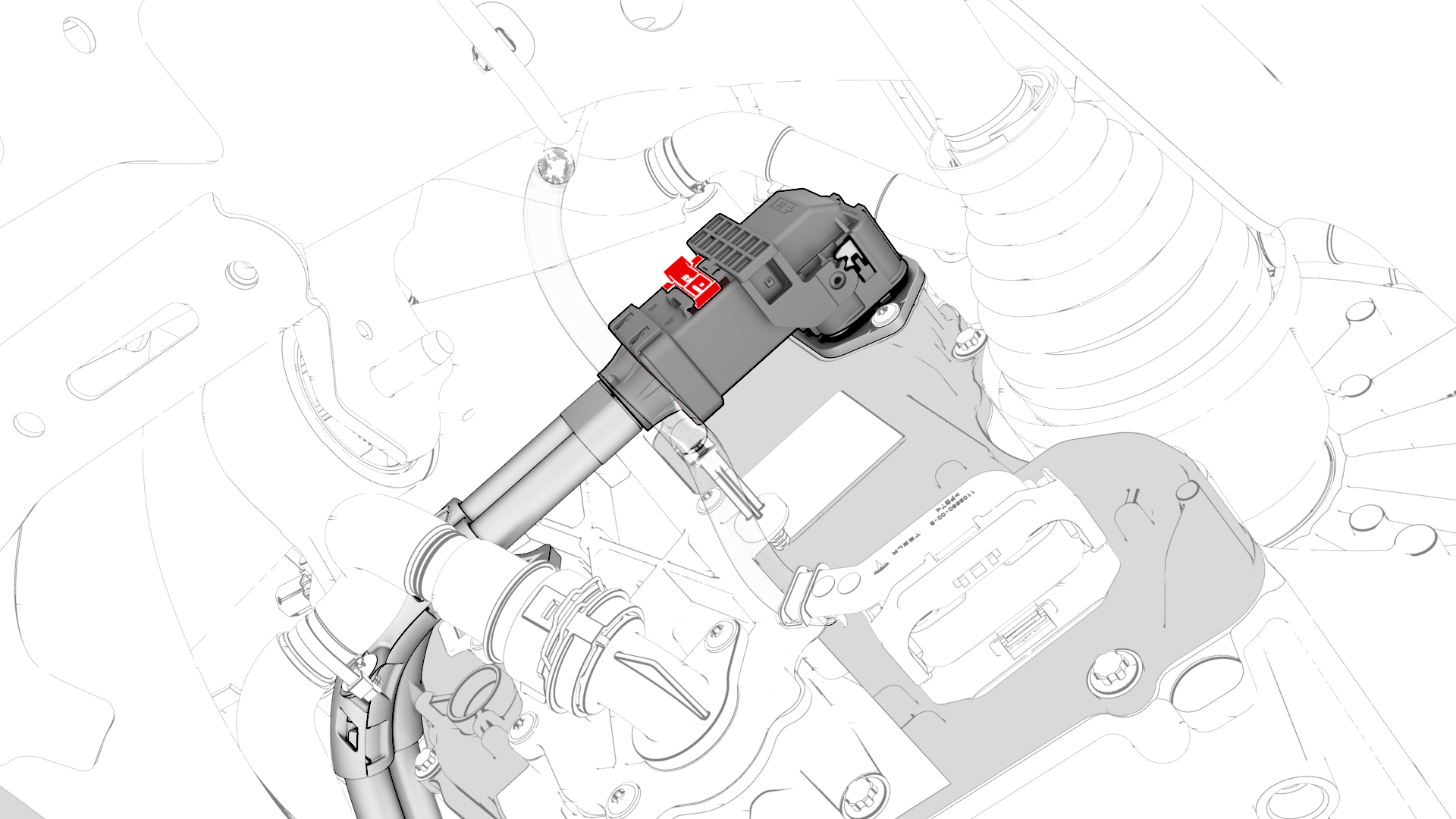
Slide the release to unlock the HV harness connector.
-
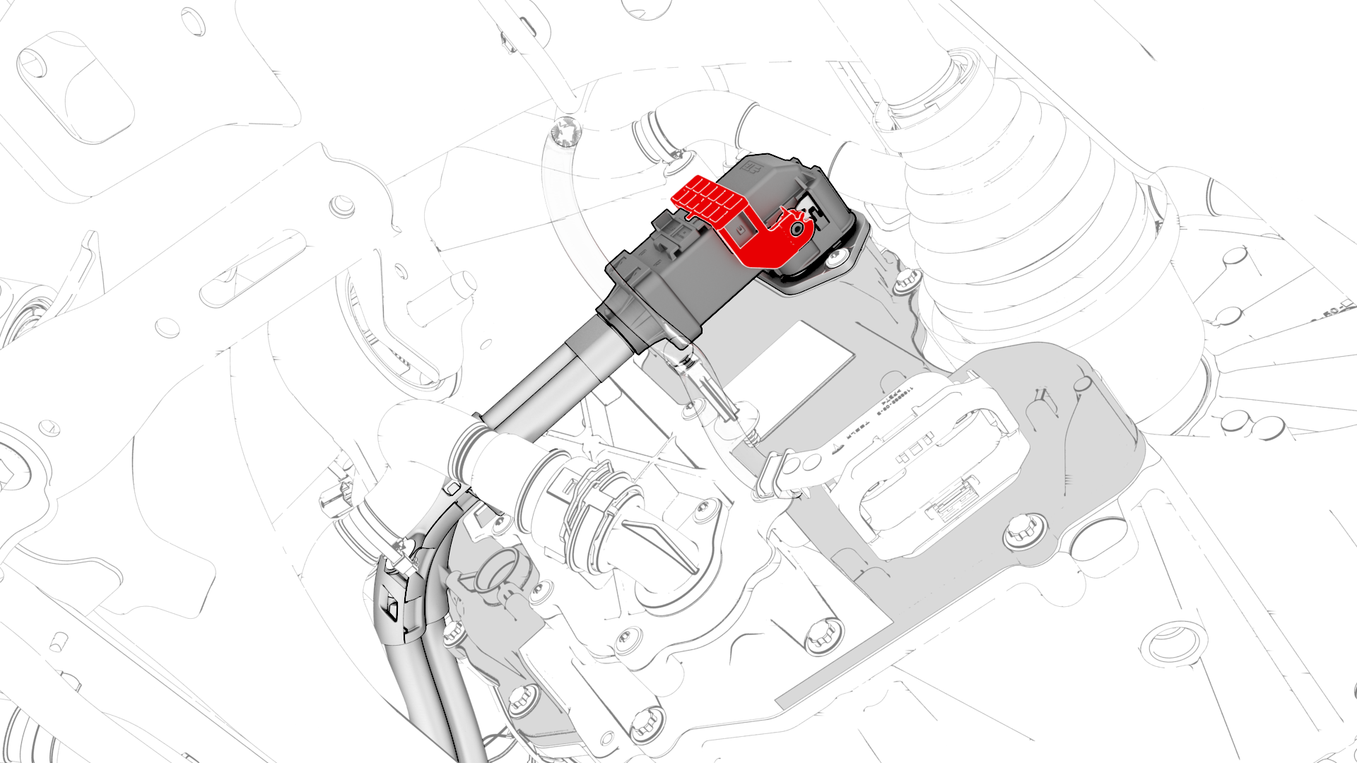
Lift the handle on HV harness connector, disconnect the harness from the inverter connector, and then remove the harness from the rear drive unit.
-
Release the clip that attaches the LH rear ABS wheel speed sensor connector to the subframe, and then disconnect the subframe harness from the connector.
 Tip: Use a mechanical pickup tool to hold the connector in place, and then release the connector clip with a screwdriver.
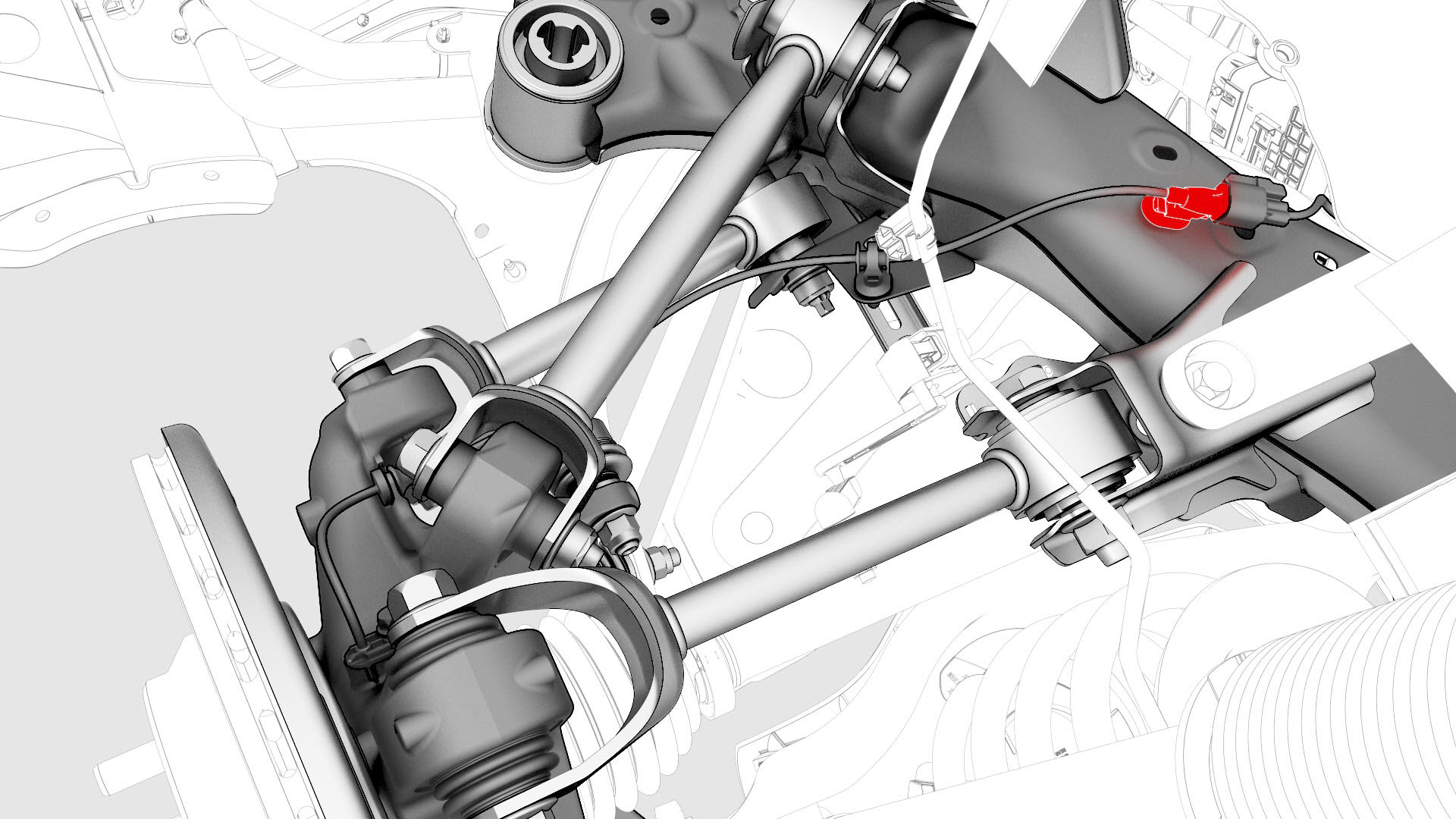
-
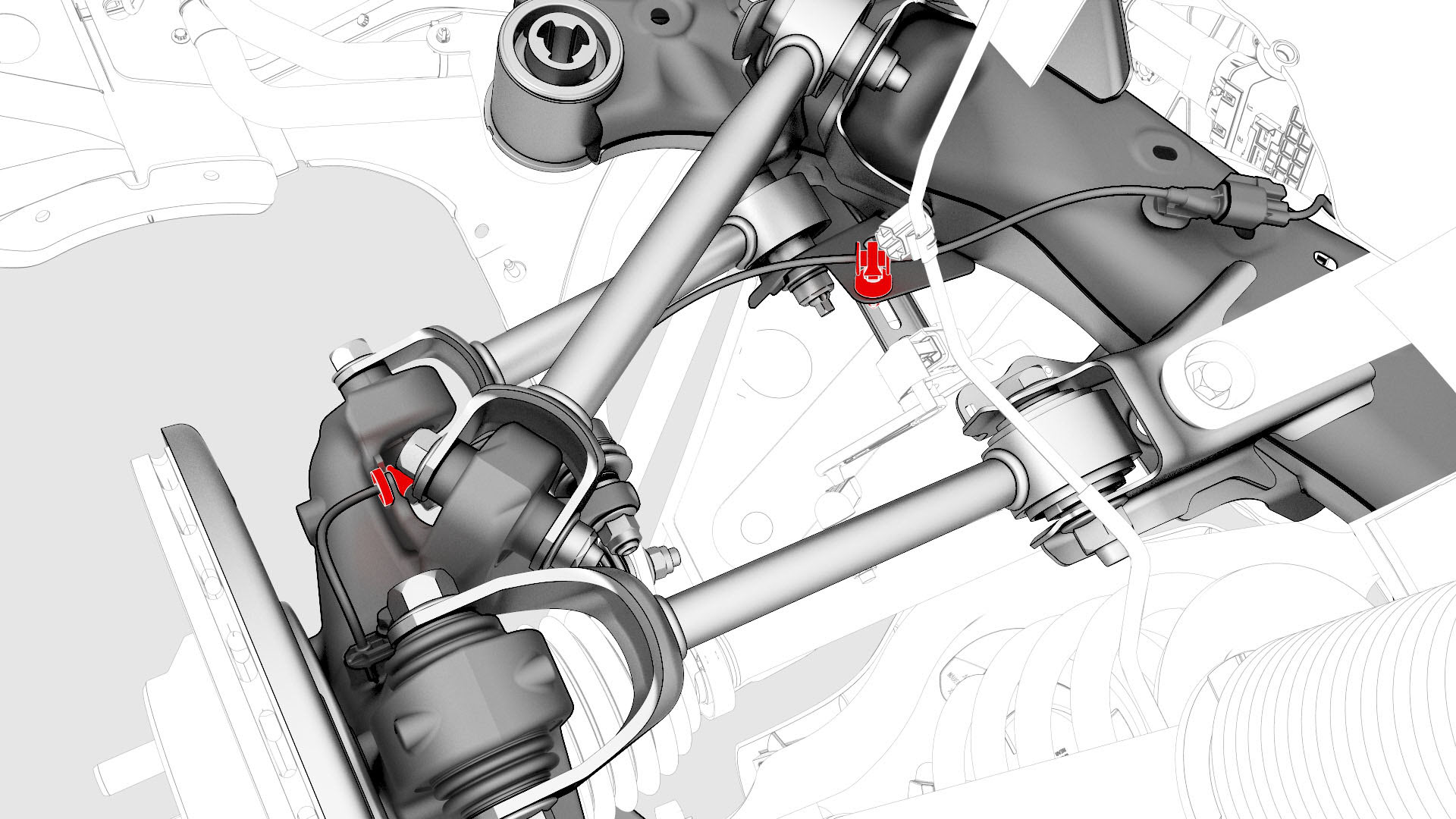
Release the clip and remove the grommet that attach the rear LH ABS wheel speed sensor cable to the rear LH knuckle and subframe bracket.
-
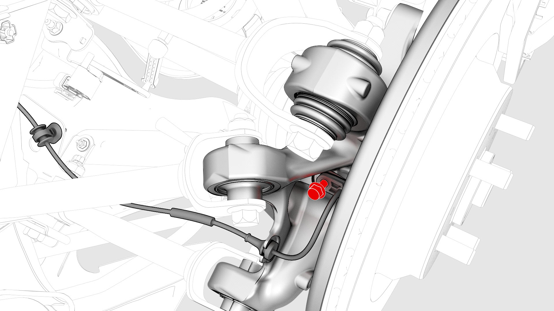
Remove and discard the bolt that attaches the rear LH ABS wheel speed sensor to the knuckle, and then remove the sensor from the knuckle.
-
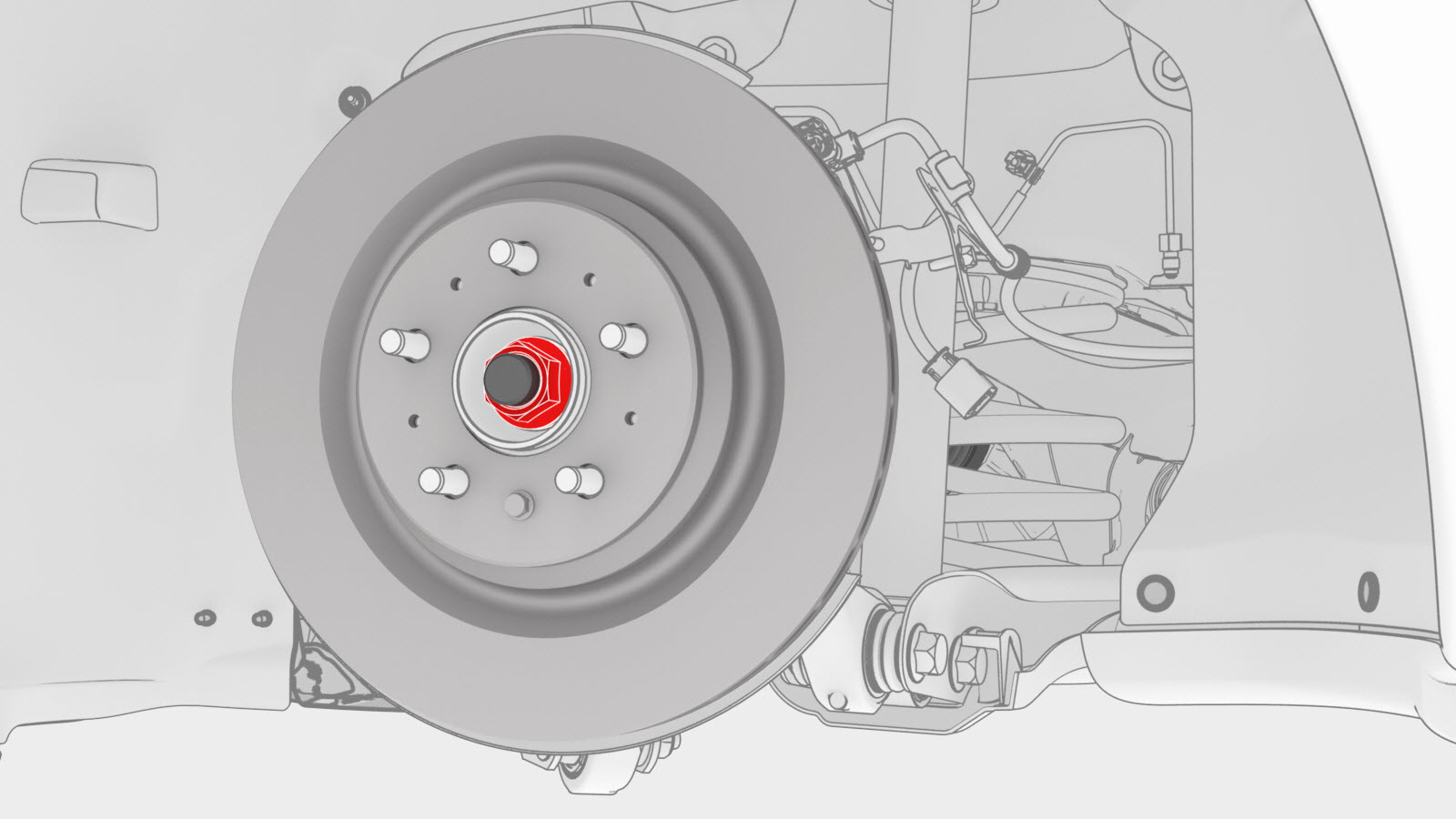
Remove and discard the nut, and remove the washer that attach the LH halfshaft to the hub assembly.
-
Remove the bolt that attaches the LH rear brake rotor to the hub.
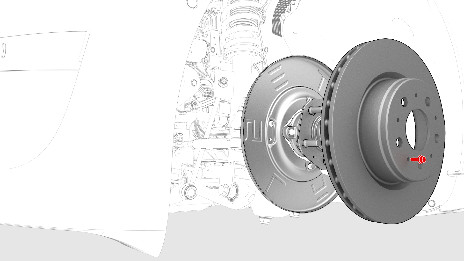 Note: Remove the lug nut previously installed for early production vehicles.
 -
Install the bolt that attaches the LH rear brake rotor to the hub.
 Torque 5 NmNote: Reinstall the lug nut previously installed for early production vehicles.
 -
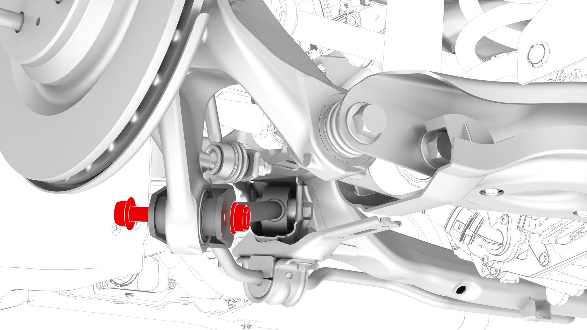
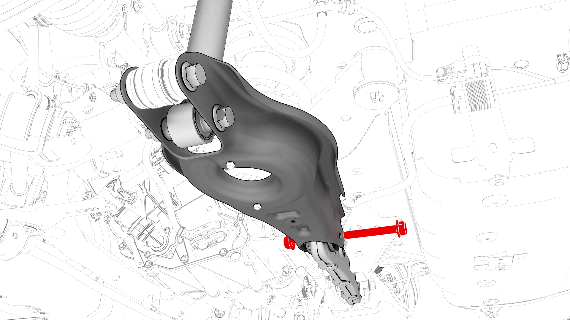
Remove the bolt and nut that attach the LH rear damper to the LH lower aft link, and then remove the damper from the rear subframe.
-
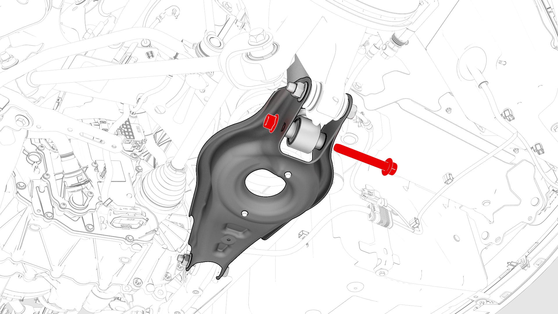
Remove the bolt and nut that attach the LH lower aft link to the knuckle.
-
Remove the bolt and nut that attach the LH lower fore link to the rear subframe.
-
Remove the nut and bolt that attach the LH upper aft link to the rear subframe.
-
Remove the nut and bolt that attach the LH toe link to the rear subframe.
-
With an assistant, remove the bolt and nut that attach the LH upper fore link to the rear subframe.
 Note: With the help of an assistant, separate the knuckle assembly from the rear subframe.
 -
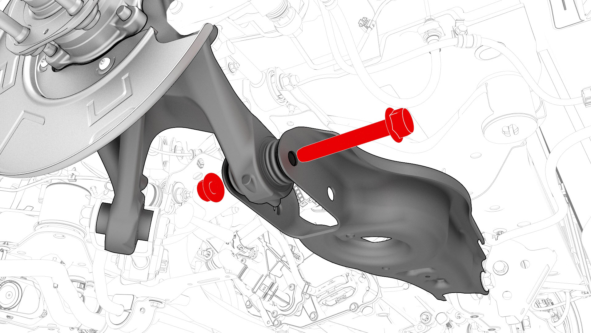
Remove the nut and bolt that attach the LH lower control arm to the rear subframe, and then remove the control arm from the rear subframe.
-
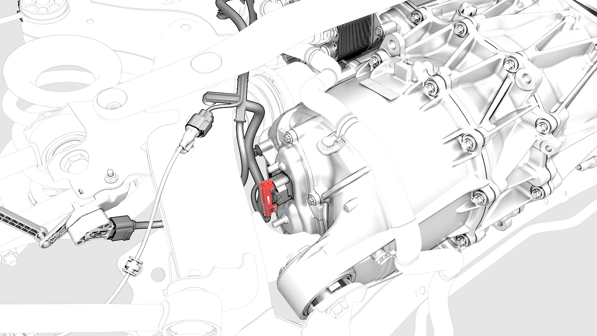
Disconnect the electrical harness from the resolver connector.
-
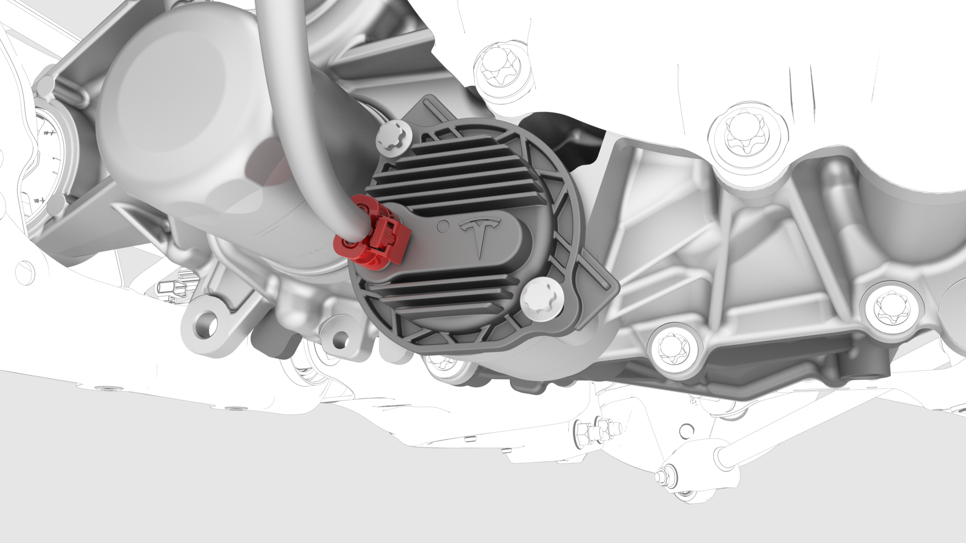
Disconnect the electrical harness from the oil pump connector.
-
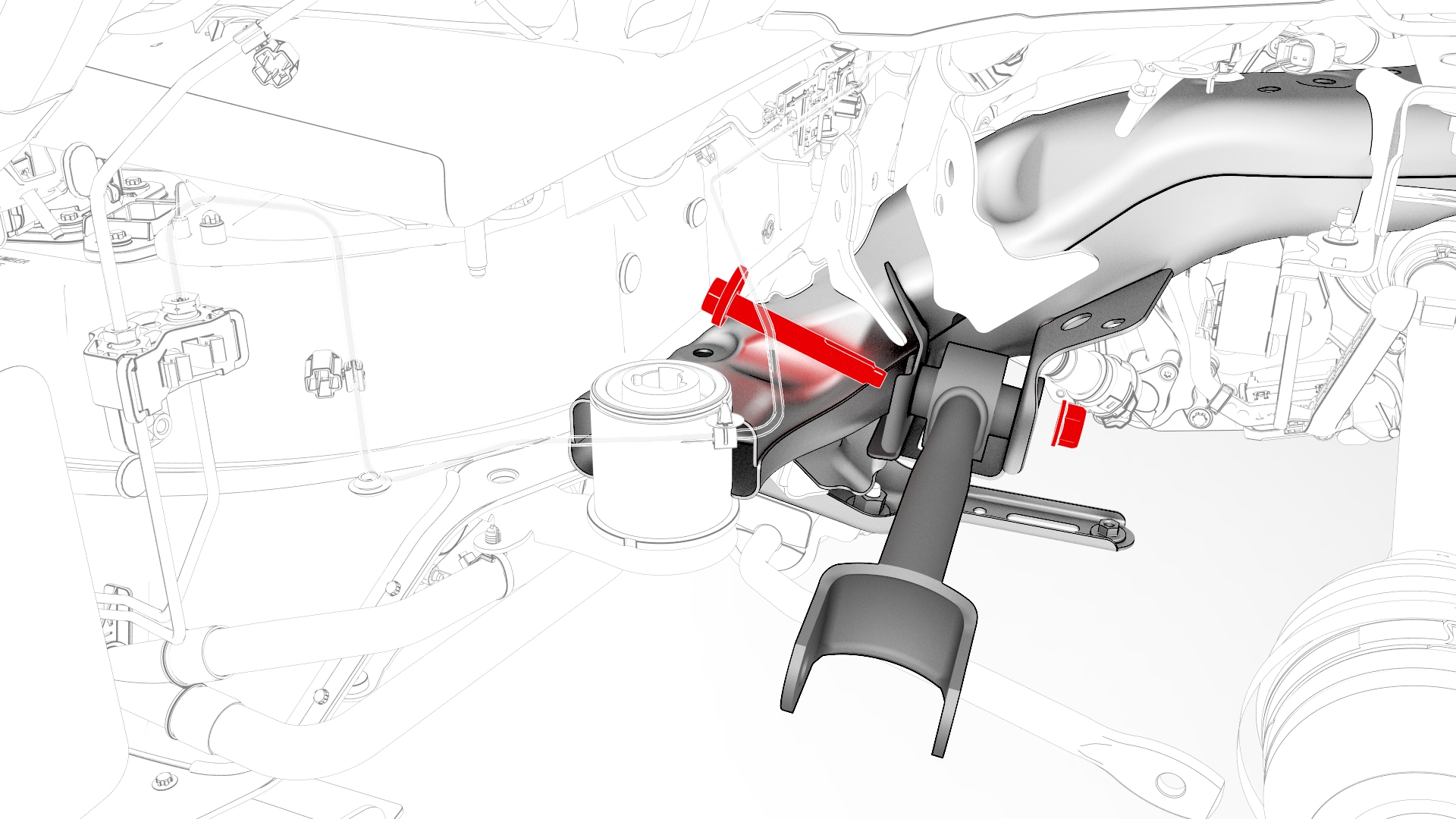
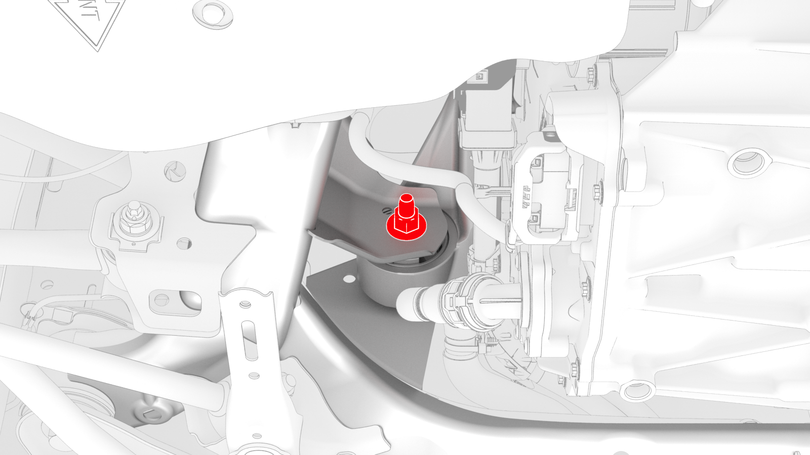
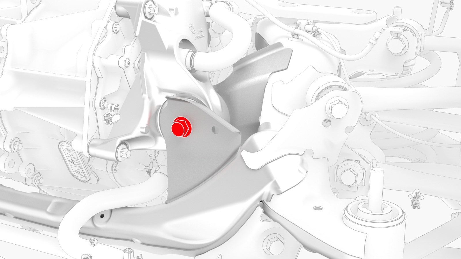
Remove the bolt and nut that attach the LH mount of the rear drive unit to the subframe.
-
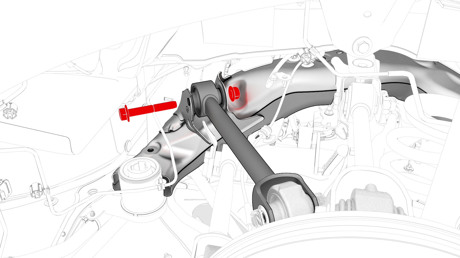
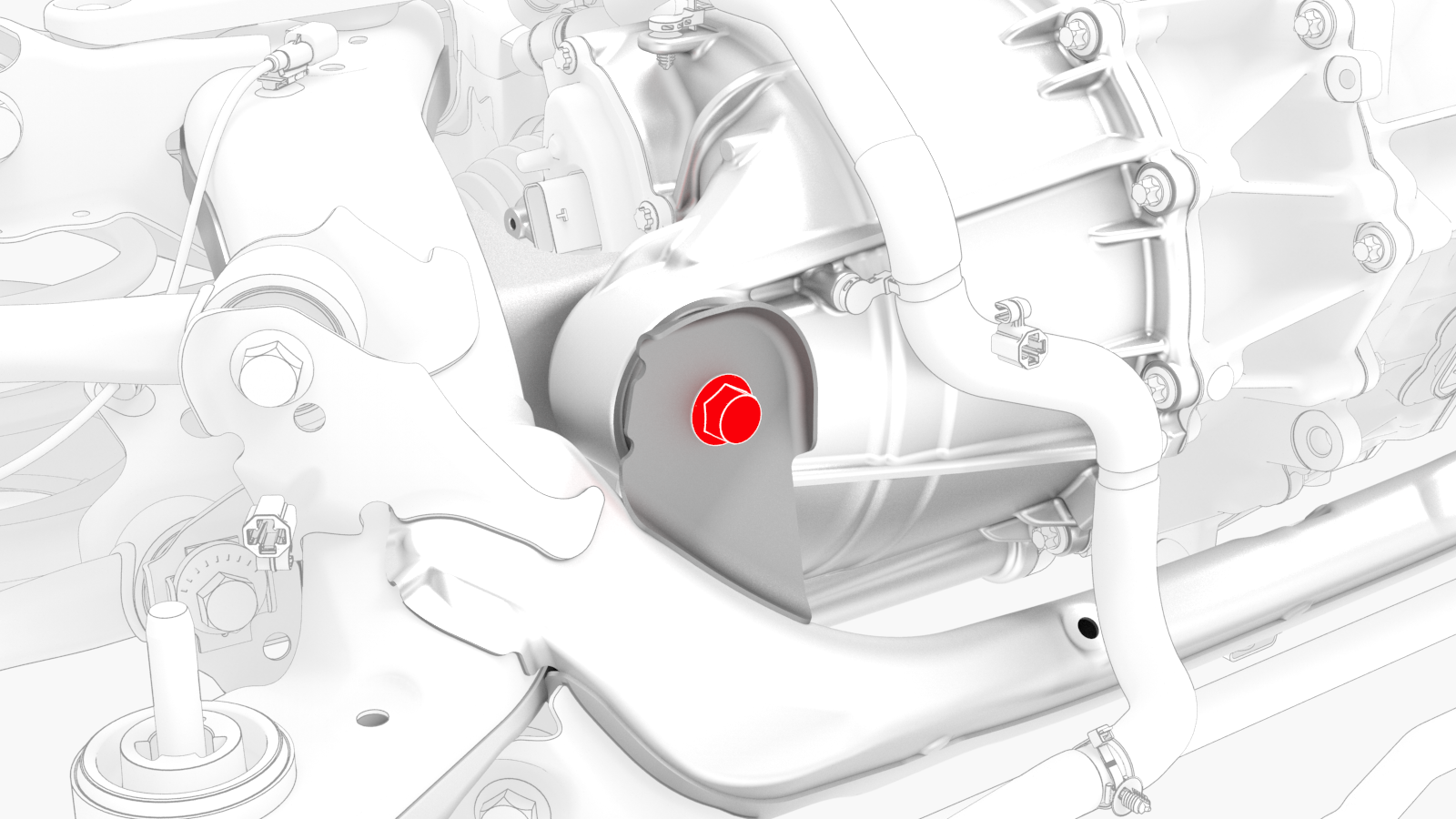
Remove the bolt and nut that attach the RH bushing of the rear drive unit to the subframe.
-
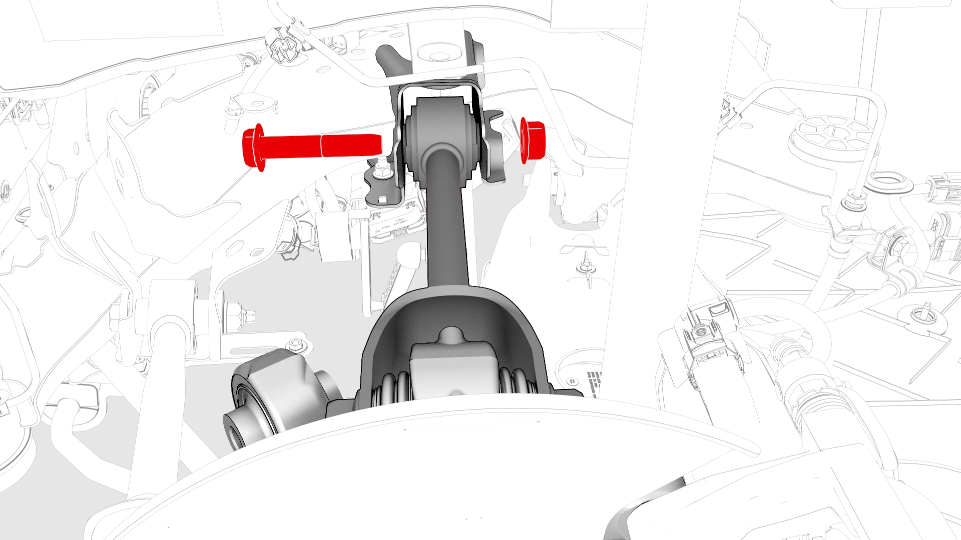
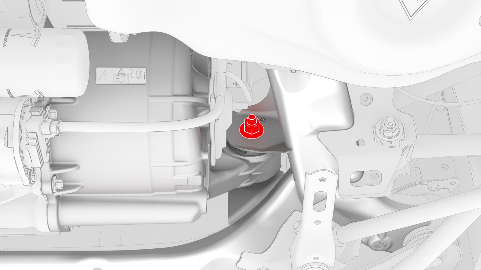
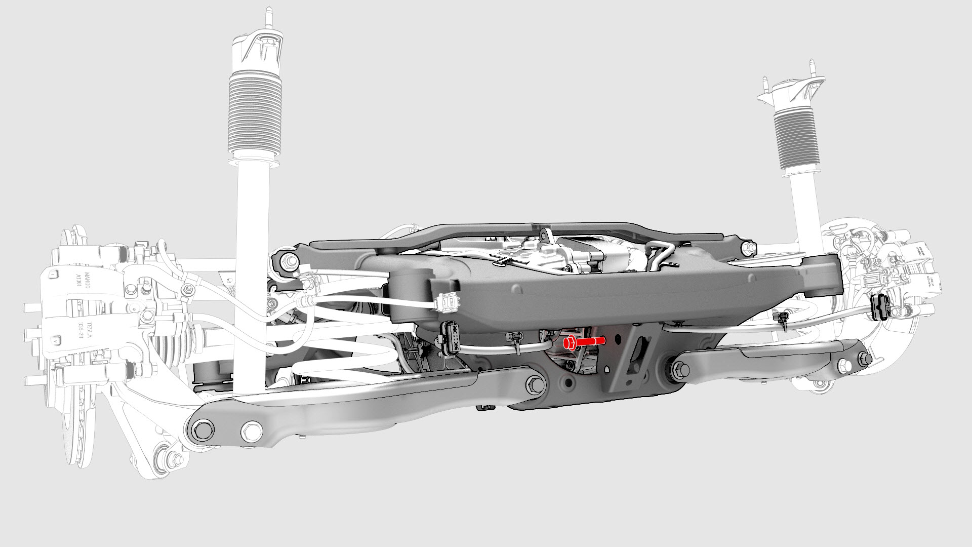
Remove the bolt and nut that attach the rear bushing of the rear drive unit to the subframe.
-
Release the clips that attach the subframe electrical harness to the bottom and top of the rear subframe, and then remove the electrical harness from the rear subframe.
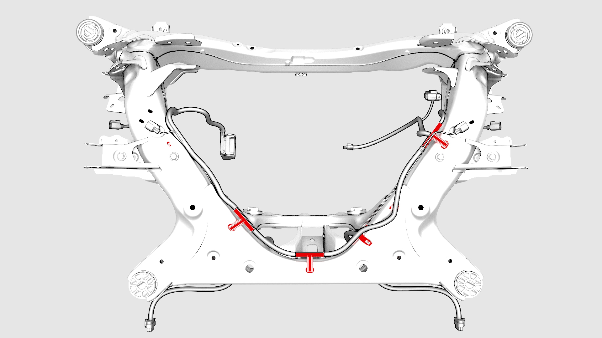 Top view of the rear subframe
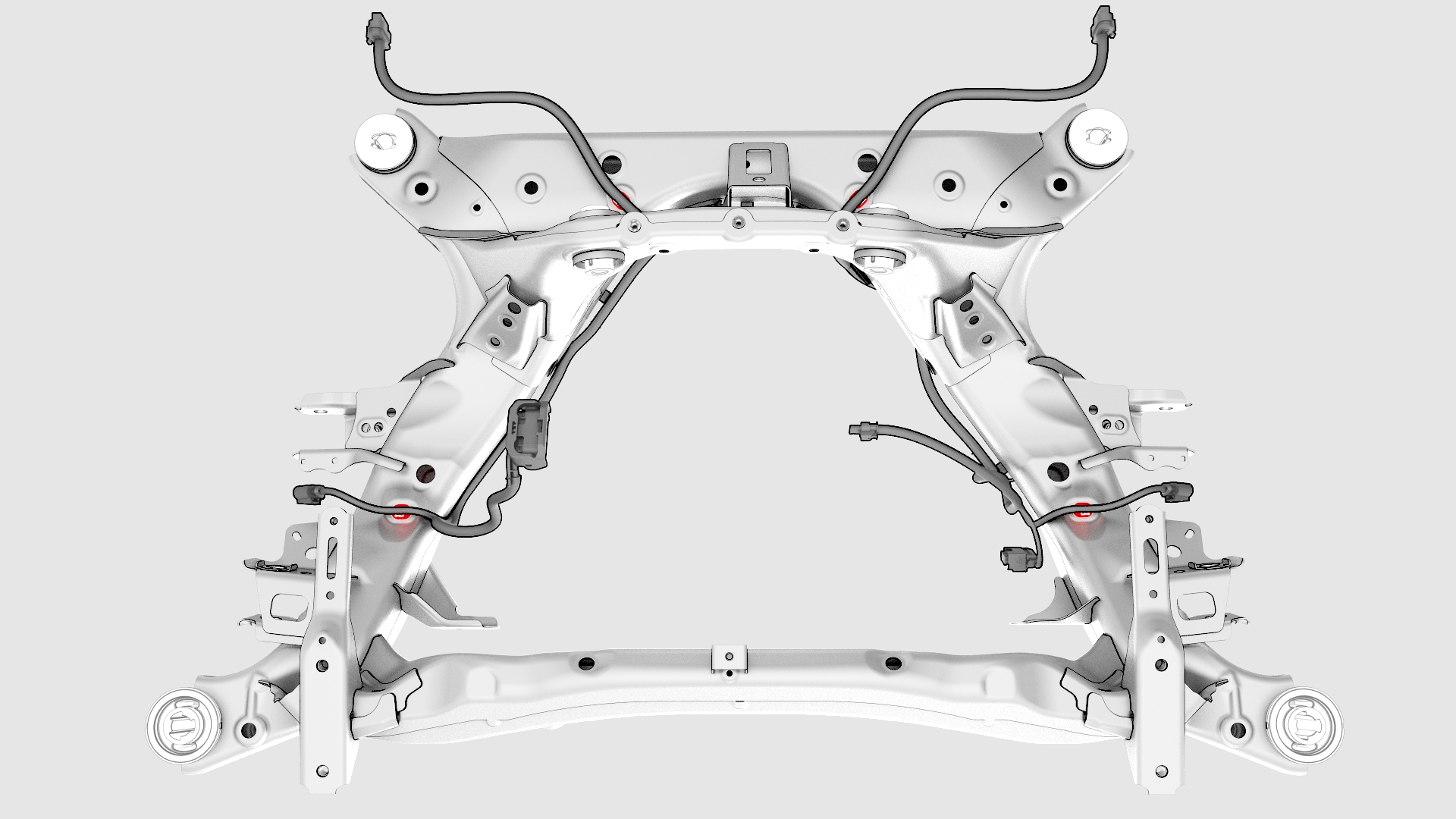 Bottom view of the rear subframe
 -
With an assistant, release the straps, and then remove the rear subframe from the subframe lifting tool.
| 1 | Remove the rear subframe assembly. See Subframe Assembly - Rear (Remove and Install). | ||
| 2 | Disconnect the electrical harness from the inverter low voltage connector. | |
| 3 | Release the clip that attaches the low voltage electrical harness to the inverter. | |
| 4 | Release the clip, disconnect the rear drive unit inlet hose from the inverter coolant inlet, and then plug the inlet. | |
| 5 | Release the clip that attaches the rear drive unit inlet hose to the HV harness bracket, and then remove the hose from the rear drive unit. | |
| 6 | Remove the bolt that attaches the HV harness bracket to the inverter. | |
| 7 | Slide the release to unlock the HV harness connector. | |
| 8 | Lift the handle on HV harness connector, disconnect the harness from the inverter connector, and then remove the harness from the rear drive unit. | |
| 9 | Drain the fluid from the rear drive unit. See Gearbox Fluid - Rear Drive Unit (Drain and Refill). | ||
| 10 | Remove the LH and RH coil springs from the rear lower aft links. | ||
| 11 | Release the clip that attaches the LH rear ABS wheel speed sensor connector to the subframe, and then disconnect the subframe harness from the connector.Tip: Use a mechanical pickup tool to hold the connector in place, and then release the connector clip with a screwdriver. | |
| 12 | Release the clip and remove the grommet that attach the rear LH ABS wheel speed sensor cable to the rear LH knuckle and subframe bracket. | |
| 13 | Remove and discard the bolt that attaches the rear LH ABS wheel speed sensor to the knuckle, and then remove the sensor from the knuckle. | |
| 14 | Remove and discard the nut, and remove the washer that attach the LH halfshaft to the hub assembly. | |
| 15 | Remove the bolt that attaches the LH rear brake rotor to the hub. Note: Remove the lug nut previously installed for early production vehicles.
| |
| 16 | Install the hub puller onto the LH rear rotor, and then install and hand-tighten the puller washers (x5) and the lug nuts (x5) onto the rotor studs. | ||
| 17 | Use the hub puller to free the LH rear halfshaft from the hub splines. Note: The halfshaft is removed at a later step.
| ||
| 18 | Remove the lug nuts (x5) and the lug nuts (x5) from the LH rear rotor studs, and then remove the hub puller from the rotor. | ||
| 19 | Install the bolt that attaches the LH rear brake rotor to the hub. Torque 5 Nm Note: Reinstall the lug nut previously installed for early production vehicles.
| |
| 20 | Remove the bolt and nut that attach the LH rear damper to the LH lower aft link, and then remove the damper from the rear subframe. | |
| 21 | Remove the bolt and nut that attach the LH lower aft link to the knuckle. | |
| 22 | Remove the bolt and nut that attach the LH lower fore link to the rear subframe. | |
| 23 | Remove the nut and bolt that attach the LH upper aft link to the rear subframe. | |
| 24 | Remove the nut and bolt that attach the LH toe link to the rear subframe. | |
| 25 | With an assistant, remove the bolt and nut that attach the LH upper fore link to the rear subframe. Note: With the help of an assistant, separate the knuckle assembly from the rear subframe.
| |
| 26 | With an assistant, separate the LH halfshaft from the hub, and then remove the LH hub and knuckle assembly from the rear subframe. | ||
| 27 | Use the axle removal tool to release the LH halfshaft from the rear drive unit, remove the halfshaft from the rear subframe, and then install a halfshaft plug into the opening of the gearbox. | ||
| 28 | Remove the nut and bolt that attach the LH lower control arm to the rear subframe, and then remove the control arm from the rear subframe. | |
| 29 | Repeat step 11 through step 28 for the RH side of the rear subframe. | ||
| 30 | Release the clip that attaches the rear drive unit ground harness to the rear subframe. | ||
| 31 | Disconnect the electrical harness from the resolver connector. | |
| 32 | Disconnect the electrical harness from the oil pump connector. | |
| 33 | Attach the drive unit sling special tool to the rear drive unit. | ||
| 34 | Position the drive unit sling tool special tool underneath the gantry, and then attach the special tool to the gantry. | ||
| 35 | Raise the drive unit sling tool so that there is a slight tension on the cables. | ||
| 36 | Remove the bolt and nut that attach the LH mount of the rear drive unit to the subframe. | |
| 37 | Remove the bolt and nut that attach the RH bushing of the rear drive unit to the subframe. | |
| 38 | Remove the bolt and nut that attach the rear bushing of the rear drive unit to the subframe. | |
| 39 | Raise the drive unit sling tool to lift the rear drive unit out of the rear subframe. | ||
Top view of the rear subframe
Bottom view of the rear subframe
| 40 | Release the clips that attach the subframe electrical harness to the bottom and top of the rear subframe, and then remove the electrical harness from the rear subframe. | |
| 41 | With an assistant, release the straps, and then remove the rear subframe from the subframe lifting tool. |
Install
-
Install the clips that attach the electrical harness to the rear subframe.
Top view of the rear subframe
Bottom view of the rear subframe
-
Install and hand-tighten the bolt and nut that attach the rear bushing of the rear drive unit to the subframe.
-
Install and hand-tighten the bolt and nut that attach the RH bushing of the rear drive unit to the subframe.
-
Install and hand-tighten the bolt and nut that attach the LH mount of the rear drive unit to the subframe.
-
Tighten the bolts and nuts that attach the rear bushing, RH bushing, and LH mount of the rear drive unit to the rear subframe.
 Torque 70 Nm
 -
Connect the electrical harness to the oil pump connector.
-
Connect the electrical harness to the resolver connector.
-
Install the LH lower aft link to the rear subframe, and then install and hand-tighten the nut and bolt that attach the LH lower aft link to the rear subframe.
-
With an assistant, install and hand-tighten the bolt and nut that attach the LH upper fore link to the rear subframe.
-
With an assistant, install and hand-tighten the nut and bolt that attach the LH toe link to the rear subframe.
-
With an assistant, install and hand-tighten the nut and bolt that attach the LH upper aft link to the rear subframe.
-
With an assistant, install and hand-tighten the bolt and nut that attach the LH lower fore link to the rear subframe.
-
With an assistant, install and hand-tighten the bolt and nut that attach the LH lower aft link to the knuckle.
-
With an assistant, install and hand-tighten the bolt and nut that attach the LH rear damper to the lower aft link.
-
Install the washer, and install a new nut to attach the halfshaft to the LH rear hub.Torque 245 Nm
-
Install the rear LH ABS wheel speed sensor to the LH rear knuckle, and then install a new bolt to secure the sensor to the knuckle.
 Torque 5 Nm
 -
Install the grommet and fasten the clip that attach the rear LH ABS wheel speed sensor cable to the rear LH knuckle and subframe bracket.
-
Connect the subframe electrical harness to the LH rear ABS wheel speed sensor connector, and then fasten the clip that attaches the sensor connector to the subframe.
-
Attach the HV connector lever lock onto the back of the HV electrical harness.
-
Firmly connect the HV electrical harness to the inverter connector.
 Caution:Make sure that the harness fits the connector squarely and tightly.
 -
While pressing the harness to the connector, fully lower the handle.
-
Slide the release to lock the HV electrical harness.
-
Install the bolt that attaches the HV harness bracket to the inverter.
 Torque 6 Nm
 -
Connect the rear drive unit inlet hose to the inverter coolant inlet, and then fasten the clip.
-
Fasten the clip that attaches the rear drive unit inlet hose to the HV harness bracket.
-
Connect the electrical harness to the inverter low voltage connector.
-
Fasten the clip that attaches the low voltage electrical harness to the inverter.
| 1 | With an assistant, install the new rear subframe onto the subframe lifting tool, and then attach the straps. | ||
Top view of the rear subframe
Bottom view of the rear subframe
| 2 | Install the clips that attach the electrical harness to the rear subframe. | |
| 3 | With an assistant, position the rear drive unit above the rear subframe, and then lower the drive unit sling tool to install the rear drive unit into the rear subframe. | ||
| 4 | Install and hand-tighten the bolt and nut that attach the rear bushing of the rear drive unit to the subframe. | |
| 5 | Install and hand-tighten the bolt and nut that attach the RH bushing of the rear drive unit to the subframe. | |
| 6 | Install and hand-tighten the bolt and nut that attach the LH mount of the rear drive unit to the subframe. | |
| 7 | Lower the drive unit sling tool to release the tension on the cables. | ||
| 8 | Remove the drive unit sling tool from the gantry. | ||
| 9 | Remove the drive unit sling tool from the rear drive unit. | ||
| 10 | Tighten the bolts and nuts that attach the rear bushing, RH bushing, and LH mount of the rear drive unit to the rear subframe. Torque 70 Nm | ||
| 11 | Connect the electrical harness to the oil pump connector. | |
| 12 | Connect the electrical harness to the resolver connector. | |
| 13 | Fasten the clip that attaches the rear drive unit ground harness to the rear subframe. | ||
| 14 | Install the LH lower aft link to the rear subframe, and then install and hand-tighten the nut and bolt that attach the LH lower aft link to the rear subframe. | |
| 15 | Remove the halfshaft plug from the gearbox, and then install the LH halfshaft to the rear drive unit. Note: Set the LH halfshaft temporarily on the lower aft link.
| ||
| 16 | With an assistant, install the halfshaft into the LH hub and knuckle assembly. Note: Make sure that the splines for the halfshaft line up.
| ||
| 17 | With an assistant, install and hand-tighten the bolt and nut that attach the LH upper fore link to the rear subframe. | |
| 18 | With an assistant, install and hand-tighten the nut and bolt that attach the LH toe link to the rear subframe. | |
| 19 | With an assistant, install and hand-tighten the nut and bolt that attach the LH upper aft link to the rear subframe. | |
| 20 | With an assistant, install and hand-tighten the bolt and nut that attach the LH lower fore link to the rear subframe. | |
| 21 | With an assistant, install and hand-tighten the bolt and nut that attach the LH lower aft link to the knuckle. | |
| 22 | With an assistant, install and hand-tighten the bolt and nut that attach the LH rear damper to the lower aft link. | |
| 23 | Install the washer, and install a new nut to attach the halfshaft to the LH rear hub. Torque 245 Nm | |
| 24 | Install the rear LH ABS wheel speed sensor to the LH rear knuckle, and then install a new bolt to secure the sensor to the knuckle. Torque 5 Nm | |
| 25 | Install the grommet and fasten the clip that attach the rear LH ABS wheel speed sensor cable to the rear LH knuckle and subframe bracket. | |
| 26 | Connect the subframe electrical harness to the LH rear ABS wheel speed sensor connector, and then fasten the clip that attaches the sensor connector to the subframe. | |
| 27 | Repeat step 14 through step 26 for the RH side of the rear subframe. | ||
| 28 | Install the LH and RH coil springs onto the rear lower aft links. | ||
| 29 | Fully raise the handle on the rear drive unit HV electrical harness. | ||
| 30 | Attach the HV connector lever lock onto the back of the HV electrical harness. | |
| 31 | Firmly connect the HV electrical harness to the inverter connector. Caution: Make sure that the harness fits the connector squarely and tightly.
| ||
| 32 | While pressing the harness to the connector, remove the HV connector lever lock. | ||
| 33 | While pressing the harness to the connector, fully lower the handle. | |
| 34 | Slide the release to lock the HV electrical harness. | |
| 35 | Install the bolt that attaches the HV harness bracket to the inverter. Torque 6 Nm | |
| 36 | Connect the rear drive unit inlet hose to the inverter coolant inlet, and then fasten the clip. | |
| 37 | Fasten the clip that attaches the rear drive unit inlet hose to the HV harness bracket. | |
| 38 | Connect the electrical harness to the inverter low voltage connector. | |
| 39 | Fasten the clip that attaches the low voltage electrical harness to the inverter. | |
| 40 | Install the rear subframe to the vehicle. See Subframe Assembly - Rear (Remove and Install). |