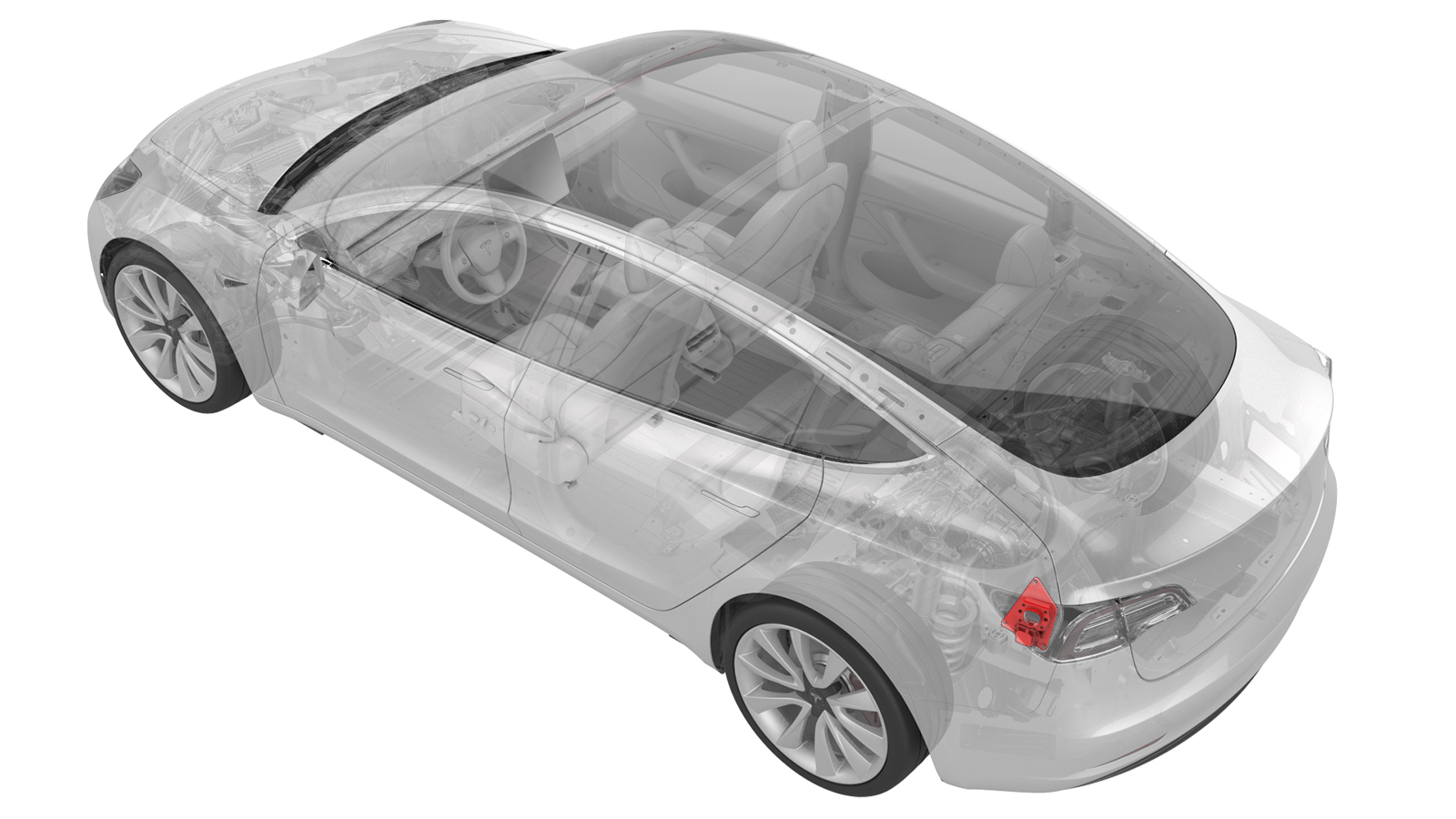
Deadfronts - Pin - Charge Port (NA) (Remove and Replace)
- 1108272-00-BCap, Logic Conn, Inv, 3DU
- 1130480-00-ATest Probes, Slim, Fluke TP38
SPECIAL TOOLS
Cap, Logic Conn, Inv, 3DU (1108272-00-B) |
Test Probes, Slim, Fluke TP38 (1130480-00-A) |
 Warning:
Only technicians who have been trained in High Voltage Awareness are permitted to perform this procedure. Proper personal protective equipment (PPE) and insulating HV gloves with a minimum rating of class 0 (1000V) must be worn at all times a high voltage cable, busbar, or fitting is handled. Refer to Tech Note TN-15-92-003, "High Voltage Awareness Care Points" for additional safety information.
Warning:
Remove all jewelry (watches, bracelets, rings, necklaces, earrings, ID tags, piercings, etc.) from your person, and all objects (keys, coins, pens, pencils, tools, fasteners, etc.) from your pockets before performing any procedure that exposes you to high voltage.
Warning:
Proper Personal Protective Equipment (PPE) is required to perform this procedure:
- High Voltage (HV) insulating gloves
- Leather glove protectors
- High voltage glove tester
- Safety glasses
- Electrical hazard rated safety shoes
Warning:
A glove inflator is the only recommended way to test HV gloves. Both HV gloves must pass testing before beginning this procedure. If either glove does not pass the air check, discard the pair.
Warning:
Make sure that the HV gloves are not expired. HV gloves can be used up to 12 months after the testing date printed on the glove, but only 6 months after first use even if the gloves are still within the 12-month period.
Remove
-
Set the Fluke 1587 insulation multimeter to measure the voltage across the 12V auxiliary battery terminals.
 Caution:If the voltage across the 12V auxiliary battery terminals is less than 10 volts or greater than 14 volts, the multimeter is not measuring reliably and must not be used. Use only a fully functional multimeter.
 -
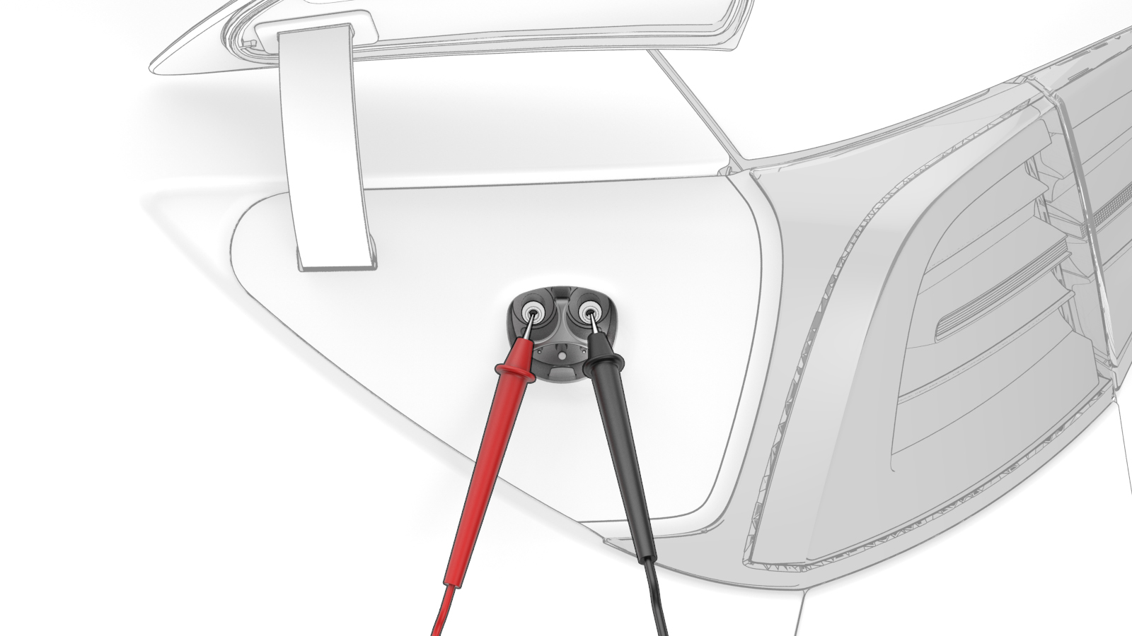
Use the multimeter with slim test probes to check voltages at the charge port terminals B+ and B-.
 Warning: If the voltage reading is greater than 10V, the HV battery contactors are closed or welded. Stop this procedure and escalate a Toolbox session, as appropriate.
 -
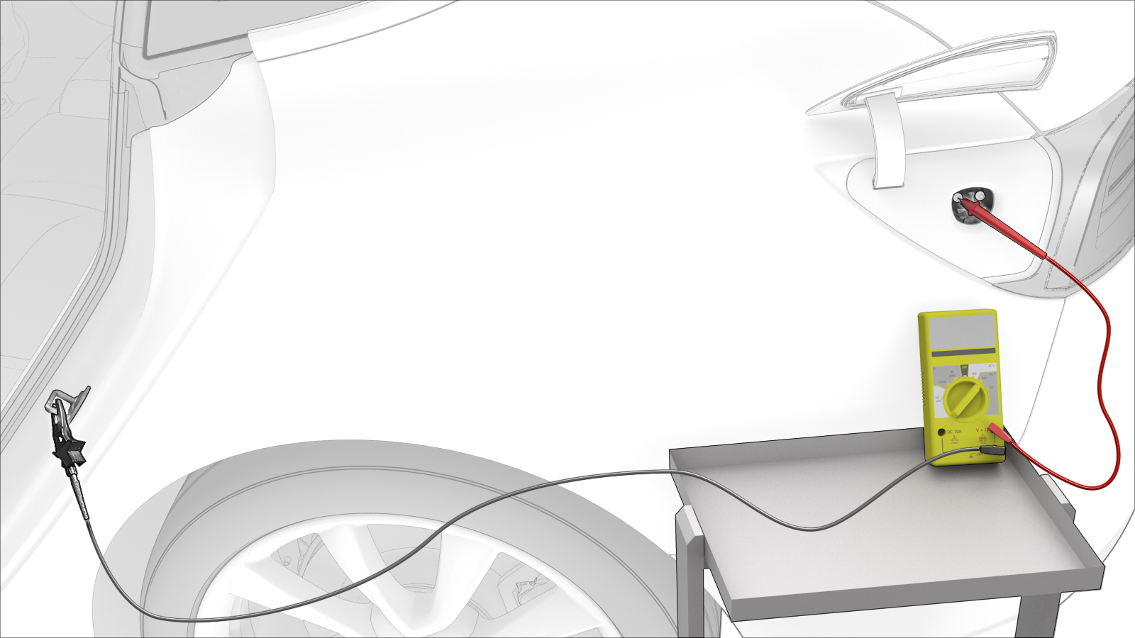
Use the multimeter to check voltages at B+ and ground.
 Warning: If the voltage reading is greater than 10V, the HV battery contactors are closed or welded. Stop this procedure and escalate a Toolbox session, as appropriate.
 -
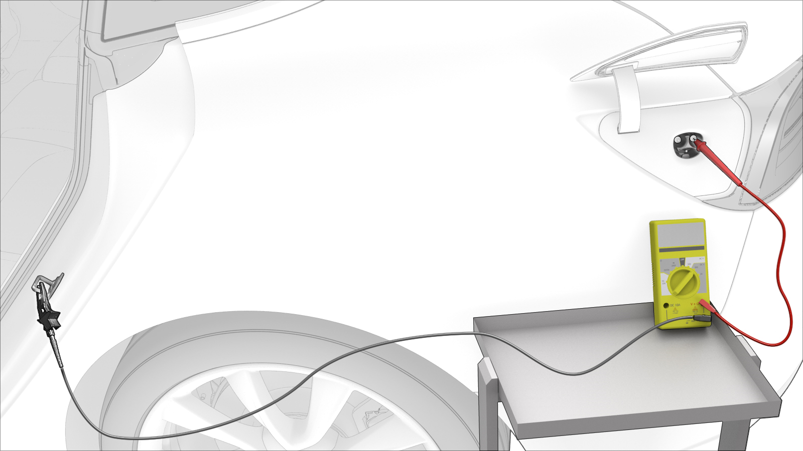
Use the multimeter to check voltages at B- and ground.
 Warning: If the voltage reading is greater than 10V, the HV battery contactors are closed or welded. Stop this procedure and escalate a Toolbox session, as appropriate.
 -
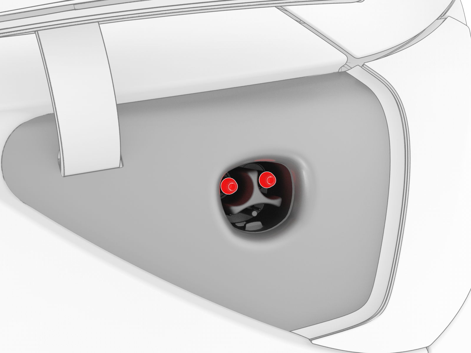
Remove the front and rear charge port pin deadfronts from the charge port assembly by carefully grabbing each deadfront with needle nose pliers, and then pull each deadfront to remove it from the charge port assembly.
| 1 | Open all doors and windows. | ||
| 2 | Move the driver seat and front passenger seat fully forward. | ||
| 3 | Remove the 2nd row lower seat cushion. See Seat Cushion - Lower - 2nd Row (Remove and Replace). | ||
| 4 | Remove the rear underhood apron. See Underhood Apron - Rear (Remove and Replace). | ||
| 5 | Open the charge port door. | ||
| 6 | Disconnect 12V power. See 12V Power (Disconnect and Connect). | ||
| 7 | Set the Fluke 1587 insulation multimeter to measure the voltage across the 12V auxiliary battery terminals. Caution: If the voltage across the 12V auxiliary battery terminals is less than 10 volts or greater than 14 volts, the multimeter is not measuring reliably and must not be used. Use only a fully functional multimeter.
| ||
| 8 | Remove all loose articles and jewelry from your person. | ||
| 9 | Put on High Voltage (HV) Personal Protective Equipment (PPE), including HV insulating gloves and leather overgloves. | ||
| 10 | Prepare a Fluke 1587 insulation multimeter with slim test probes and alligator clips. | ||
| 11 | Set the multimeter to measure DC voltage. | ||
| 12 | Use the multimeter with slim test probes to check voltages at the charge port terminals B+ and B-.Warning: If the voltage reading is greater than 10V, the HV battery contactors are closed or welded. Stop this procedure and escalate a Toolbox session, as appropriate. | |
| 13 | Use the multimeter to check voltages at B+ and ground.Warning: If the voltage reading is greater than 10V, the HV battery contactors are closed or welded. Stop this procedure and escalate a Toolbox session, as appropriate. | |
| 14 | Use the multimeter to check voltages at B- and ground.Warning: If the voltage reading is greater than 10V, the HV battery contactors are closed or welded. Stop this procedure and escalate a Toolbox session, as appropriate. | |
| 15 | Inspect the charge port for any broken or dislodged pin deadfronts and remove them with needle nose pliers. | ||
| 16 | Remove the front and rear charge port pin deadfronts from the charge port assembly by carefully grabbing each deadfront with needle nose pliers, and then pull each deadfront to remove it from the charge port assembly. | |
| 17 | Clean any leftover pin deadfront debris from the charge port assembly with an ESD-safe vacuum. |
Install
-
Insert a new charge port pin deadfront onto a 3 mm hex bit socket, and then use a socket extension to push the deadfront into a charge port assembly power terminal until it is fully seated. Repeat this step for the other deadfront pin and power terminal.
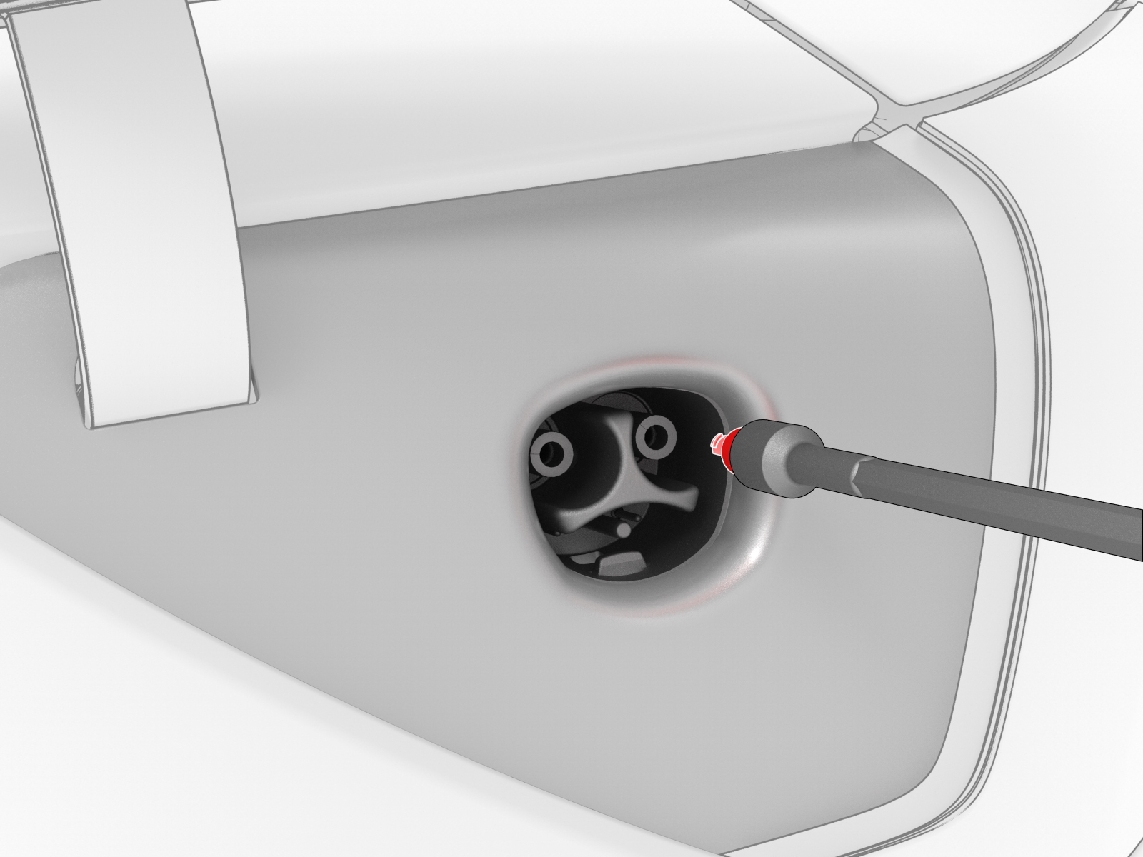 Caution:Make sure that the pin deadfront is fully seated in the terminal.
| 1 | Insert a new charge port pin deadfront onto a 3 mm hex bit socket, and then use a socket extension to push the deadfront into a charge port assembly power terminal until it is fully seated. Repeat this step for the other deadfront pin and power terminal. Caution: Make sure that the pin deadfront is fully seated in the terminal.
| |
| 2 | Reconnect 12V power. See 12V Power (Disconnect and Connect). | ||
| 3 | Install the 2nd row lower seat cushion. See Seat Cushion - Lower - 2nd Row (Remove and Replace). | ||
| 4 | Verify that the vehicle charges normally. | ||
| 5 | Install the rear underhood apron. See Underhood Apron - Rear (Remove and Replace). | ||
| 6 | Install the 2nd row lower seat cushion. See Seat Cushion - Lower - 2nd Row (Remove and Replace). | ||
| 7 | Restore the driver seat and front passenger seat back to their original position. |