HV Battery Air Leak Test
Correction code 161020010161020010
- 1026636-00-A Pack Enclosure Leak Tester, HV Battery
- 1140501-00-A Pack Kit, Enclosure, Leak Test, HV Battery, Complete
- 1144879-00-A Kit, Encl Leak Test Adapters, HV Battery
SPECIAL TOOLS
Pack Enclosure Leak Tester, HV Battery (1026636-00-A) |
Pack Kit, Enclosure, Leak Test, HV Battery, Complete (1140501-00-A) |
Kit, Encl Leak Test Adapters, HV Battery (1144879-00-A) |
Procedure
-
Release the clips that attach the low voltage electrical harness to the charge port to HV battery harness bracket at the penthouse.
-
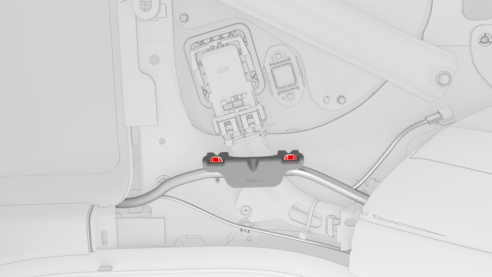
Remove the bolts that attach the charge port to HV battery harness bracket at the penthouse, and then remove the bracket from the vehicle.
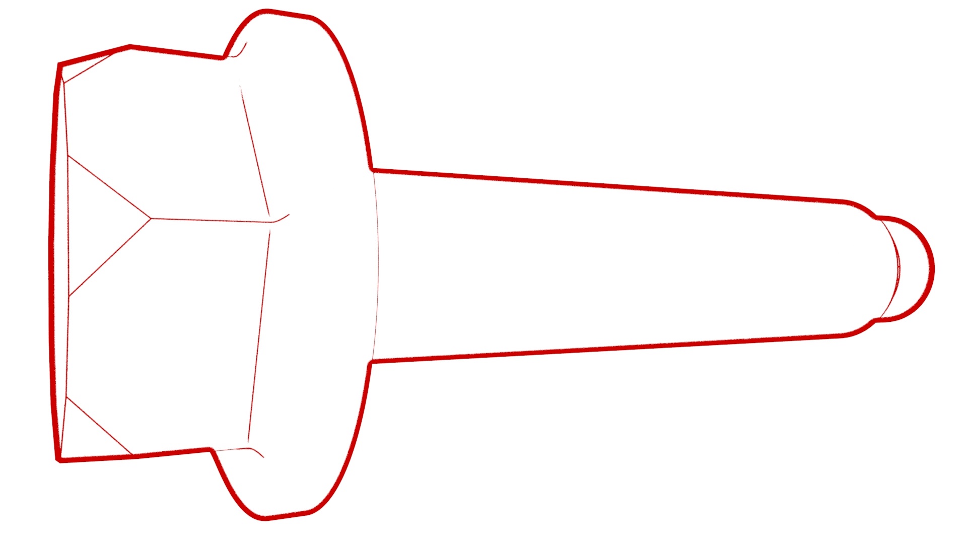 Torque 10 Nm
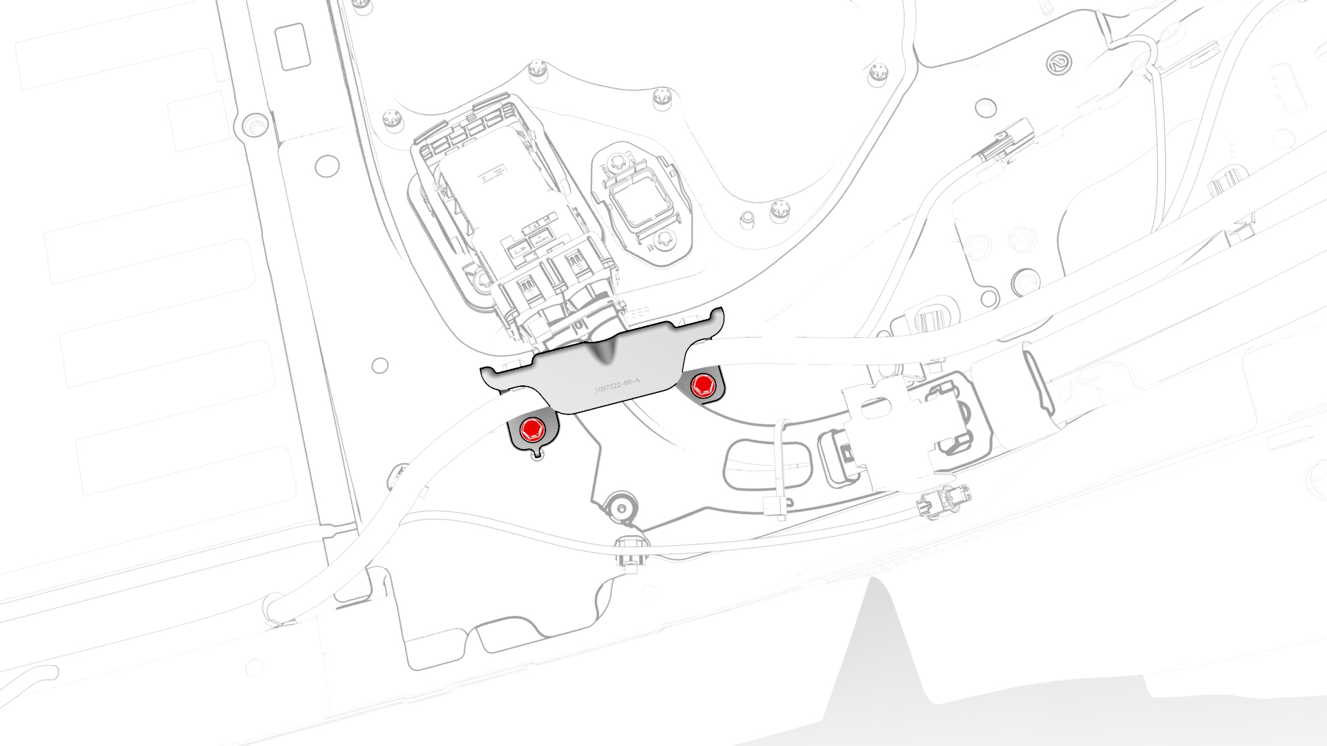
-
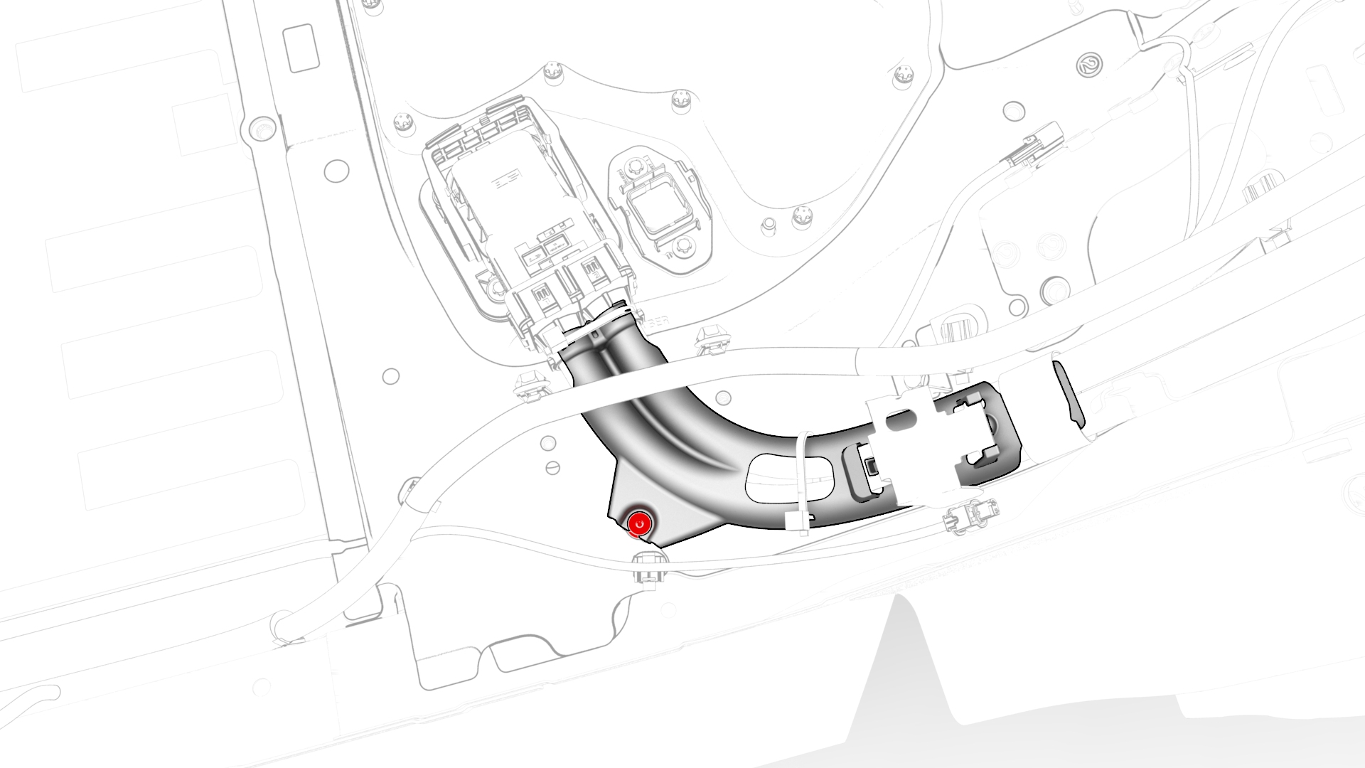
Release the clip that attaches the wiring harness to the LH lower C-pillar.
-
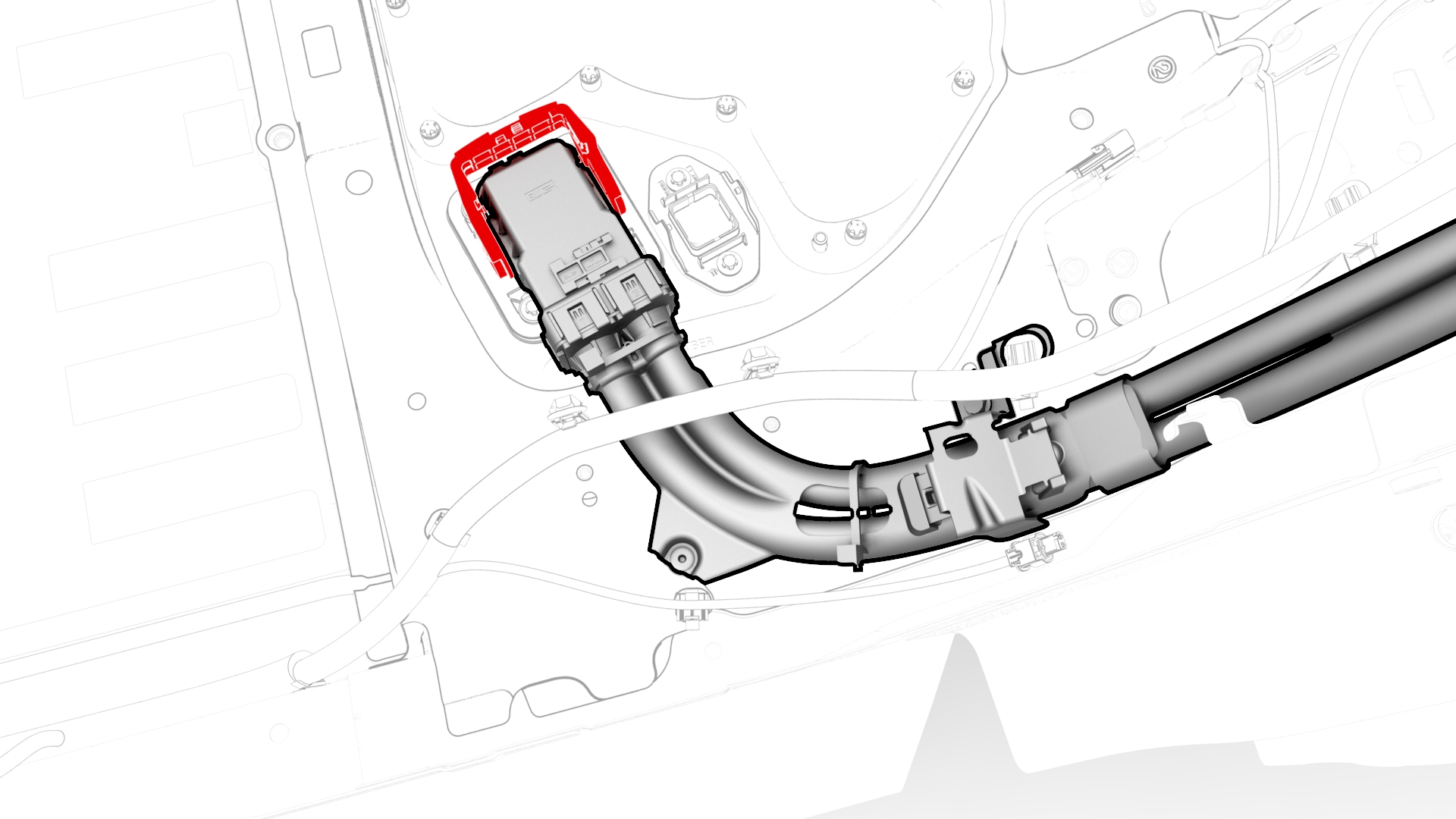
Raise the handle to disconnect the wiring harness from the DC input assembly.
-
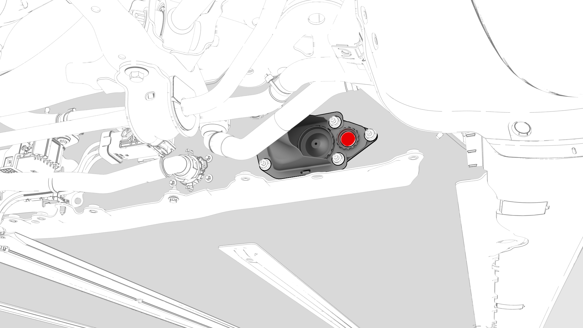
Remove and discard the breather from the RH HV battery vent shroud assembly.
-
Install the second leak test adapter plug into the RH shroud assembly.
-
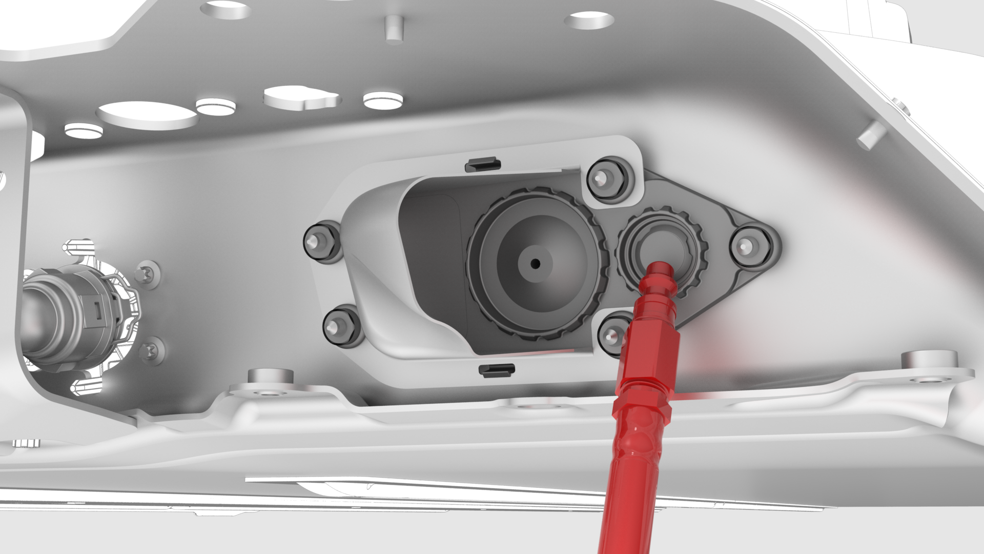
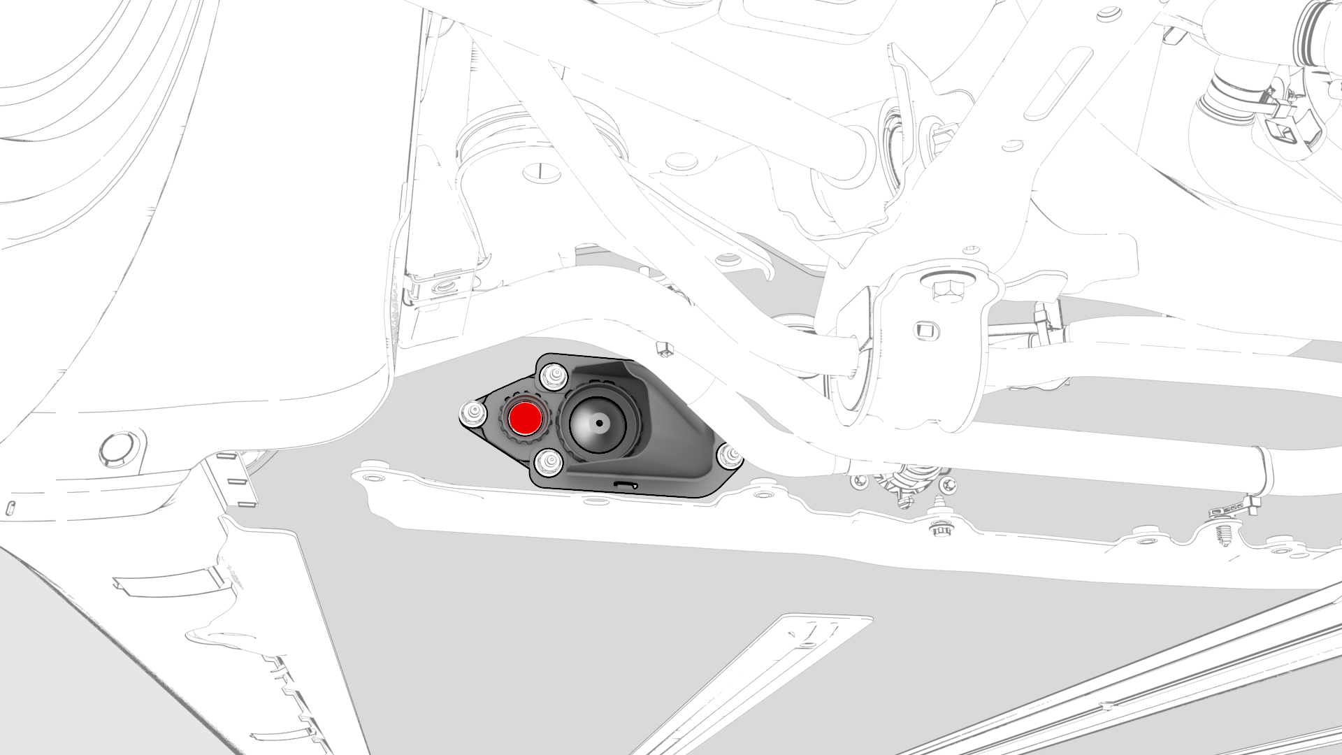
Remove and discard the breather from the LH HV battery vent shroud assembly.
-
Install the leak test adapter into the LH shroud assembly.
-
Connect the charge port to HV battery wiring harness to the DC input assembly and lower the handle.
-
Fasten the clip that attaches the charge port to HV battery wiring harness to the LH lower C-pillar.
-
Install the charge port to HV battery wiring harness bracket to the penthouse, and then install the bolts that attach the bracket to the penthouse.Torque 10 Nm
-
Fasten the clips that attach the low voltage electrical harness to the charge port to HV battery harness bracket at the penthouse.
| 1 | Perform the vehicle electrical isolation procedure. See Vehicle Electrical Isolation Procedure. | ||
| 2 | Remove the penthouse HV and penthouse 12V caps. | ||
| 3 | Remove the LH rear sill panel trim. See Trim - Sill Panel - Rear - LH (Remove and Replace). | ||
| 4 | Release the clips that attach the low voltage electrical harness to the charge port to HV battery harness bracket at the penthouse. | |
| 5 | Remove the bolts that attach the charge port to HV battery harness bracket at the penthouse, and then remove the bracket from the vehicle. Torque 10 Nm | |
| 6 | Release the clip that attaches the wiring harness to the LH lower C-pillar. | |
| 7 | Raise the handle to disconnect the wiring harness from the DC input assembly. | |
| 8 | Install the dummy plug to the DC input assembly. | ||
| 9 | Install the dummy plug into the HVC connector. | ||
| 10 | Remove and discard the breather from the penthouse probe lid cover. | ||
| 11 | Install the leak test adapter plug into the penthouse probe lid cover. | ||
| 12 | Remove the mid aero shield panel. See Panel - Aero Shield - Mid (Remove and Replace). | ||
| 13 | Remove and discard the breather from the RH HV battery vent shroud assembly. | |
| 14 | Install the second leak test adapter plug into the RH shroud assembly. | |
| 15 | Remove and discard the breather from the LH HV battery vent shroud assembly. | |
| 16 | Install the leak test adapter into the LH shroud assembly. | |
| 17 | Connect the pack enclosure leak tester to the leak test adapter in the LH HV battery shroud assembly. | ||
| 18 | Close both valves on the pack enclosure leak tester, and then connect a compressed air supply line. | ||
| 19 | Fully close the regulator, and then open the inlet valve. | ||
| 20 | Set the regulator to 0.15 psi. | ||
| 21 | Open the outlet valve, and allow at least 45 seconds for the pressure to stabilize to 0.15 psi. | ||
| 22 | Close the inlet valve, record the starting pressure displayed, and then start a 60-second timer. | ||
| 23 | After 60 seconds record the ending pressure displayed. | ||
| 24 | Subtract the ending pressure from the starting pressure, and if:
| ||
| 25 | Disconnect the air supply from the pack enclosure leak tester. | ||
| 26 | Open the inlet valve, and then disconnect the pack enclosure leak tester from the leak test adapter in the LH HV battery shroud assembly. | ||
| 27 | Remove the leak test adapter from the LH HV battery shroud assembly, and then install a new breather into the LH shroud assembly. | ||
| 28 | Remove the leak test adapter plug from the RH HV battery shroud assembly, and then install a new breather into the RH shroud assembly. | ||
| 29 | Install the mid aero shield panel. See Panel - Aero Shield - Mid (Remove and Replace). | ||
| 30 | Remove the leak test adapter from the penthouse probe lid cover. | ||
| 31 | Install a new breather into the penthouse probe lid cover. | ||
| 32 | Remove the logic connector cap and dummy plug from the high voltage controller connector and the DC input assembly. | ||
| 33 | Connect the charge port to HV battery wiring harness to the DC input assembly and lower the handle. | |
| 34 | Fasten the clip that attaches the charge port to HV battery wiring harness to the LH lower C-pillar. | |
| 35 | Install the charge port to HV battery wiring harness bracket to the penthouse, and then install the bolts that attach the bracket to the penthouse. Torque 10 Nm | |
| 36 | Fasten the clips that attach the low voltage electrical harness to the charge port to HV battery harness bracket at the penthouse. | |
| 37 | Install the LH rear sill panel trim. See Trim - Sill Panel - Rear - LH (Remove and Replace). | ||
| 38 | Install the penthouse HV and penthouse 12v caps. | ||
| 39 | Connect 12 V power. See 12V Power (Disconnect and Connect). |