Coolant - HV Battery (Drain and Refill)
Correction code 1620050516200505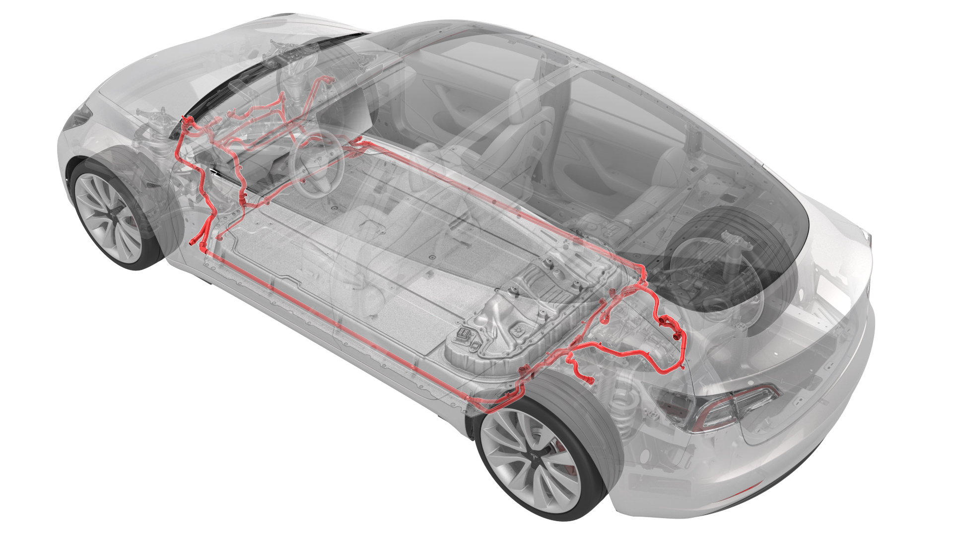
- 1053600-00-BDrive Unit Pressure Test Fixture
- 1130942-00-BAdapter, Coolant Reservoir Pressure Test
- 1132185-00-BKit, Coolant Leak Test Adapters, Model 3
- 1133843-00-A Kit, Coolant Drain & Fill Adapters, M3
- 1135762-00-AKit, Svc Plug, Cooling Hose, Model 3
- GSN-TL-000564Kit, Battery Coolant Drain and Fill
SPECIAL TOOLS
Drive Unit Pressure Test Fixture (1053600-00-B) |
Adapter, Coolant Reservoir Pressure Test (1130942-00-B) |
Kit, Coolant Leak Test Adapters, Model 3 (1132185-00-B) |
Kit, Coolant Drain & Fill Adapters, M3 (1133843-00-A) |
Kit, Svc Plug, Cooling Hose, Model 3 (1135762-00-A) |
Kit, Battery Coolant Drain and Fill (GSN-TL-000564) |
Remove
-
Remove the lower clips (x3) that attach the lower rear edge of the LH wheel arch liner to the body, to allow access to the coolant hose.
-
Remove the lower clips (x3) that attach the lower rear edge of the RH wheel arch liner to the body, to allow access to the coolant hose.
| 1 | Remove the cabin intake duct assembly. See Duct - Cabin Intake (Remove and Replace). | ||
| 2 | Remove the front HV battery skid plate. See Skid Plate - HV Battery - Front (Remove and Replace). | ||
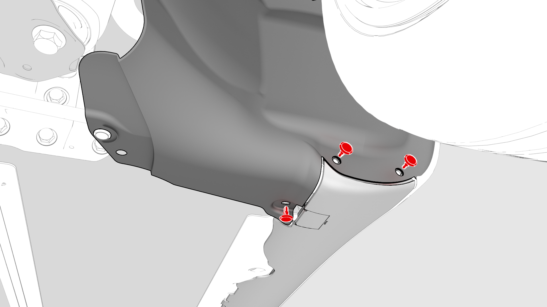
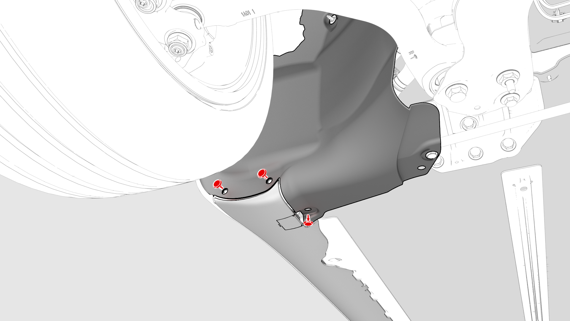
| 3 | Remove the lower clips (x3) that attach the lower rear edge of the LH wheel arch liner to the body, to allow access to the coolant hose. | |
| 4 | Remove the lower clips (x3) that attach the lower rear edge of the RH wheel arch liner to the body, to allow access to the coolant hose. | |
| 5 | Drain the coolant. See Drain. |
Drain
The following steps drain the power conversion system within the HV battery and the rear drive unit.
-
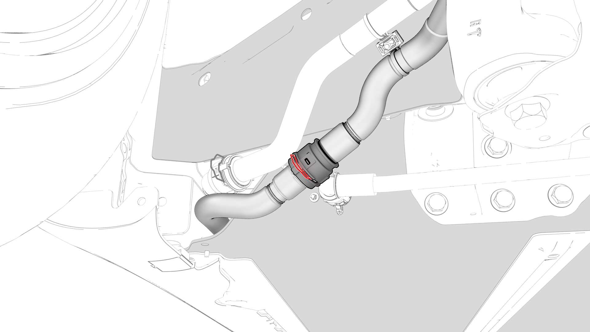
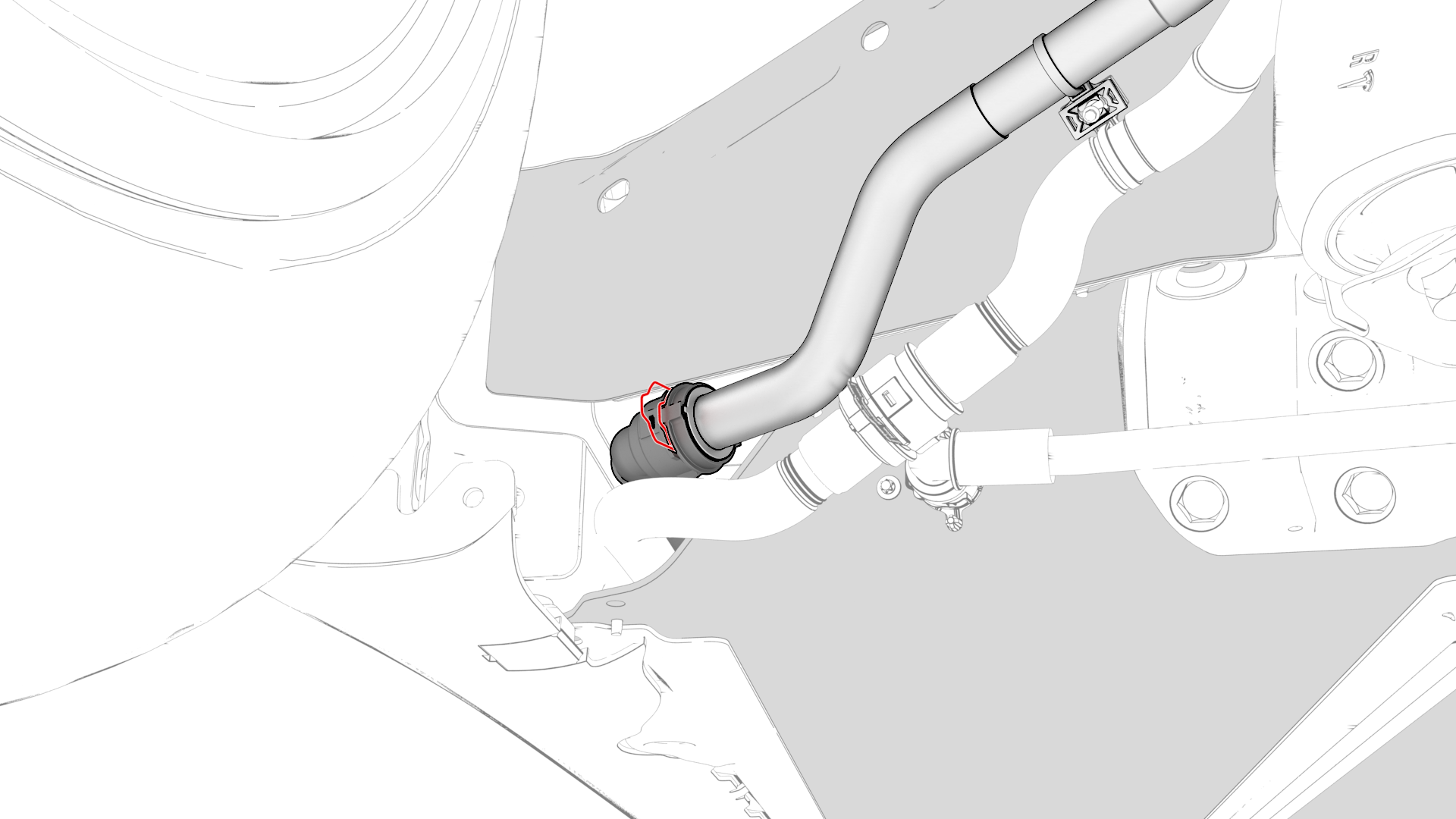
Disconnect the powertrain return hose at the RH side of the vehicle and plug the female connector.
-
Disconnect the rear powertrain supply hose at the RH side of the vehicle and plug the male connector.
| 1 | Position a coolant drain under the front RH corner of the HV battery. | ||
| 2 | Disconnect the powertrain return hose at the RH side of the vehicle and plug the female connector. | |
| 3 | Attach the drain fitting adapter to the male connector, and position over the coolant drain. | ||
| 4 | Disconnect the rear powertrain supply hose at the RH side of the vehicle and plug the male connector. | |
| 5 | Attach the pressure fitting adapter to the female connector. | ||
| 6 | Make sure the valve on the pressure regulator is closed and the regulator is set to zero. | ||
| 7 | Attach the coolant pressure tester to the pressure fitting adapter. | ||
| 8 | Attach the compressed air line to the regulator and set the regulator to 20 psi. | ||
| 9 | Open the valve on the drain fitting adapter. | ||
| 10 | Slowly open the valve on the regulator and allow the coolant to drain. | ||
| 11 | Close the valve on the regulator and disconnect the compressed air line from the regulator. | ||
| 12 | Disconnect the drain fitting adapter and pressure fitting adapter from the connectors. |
The following steps drain the HV battery core.
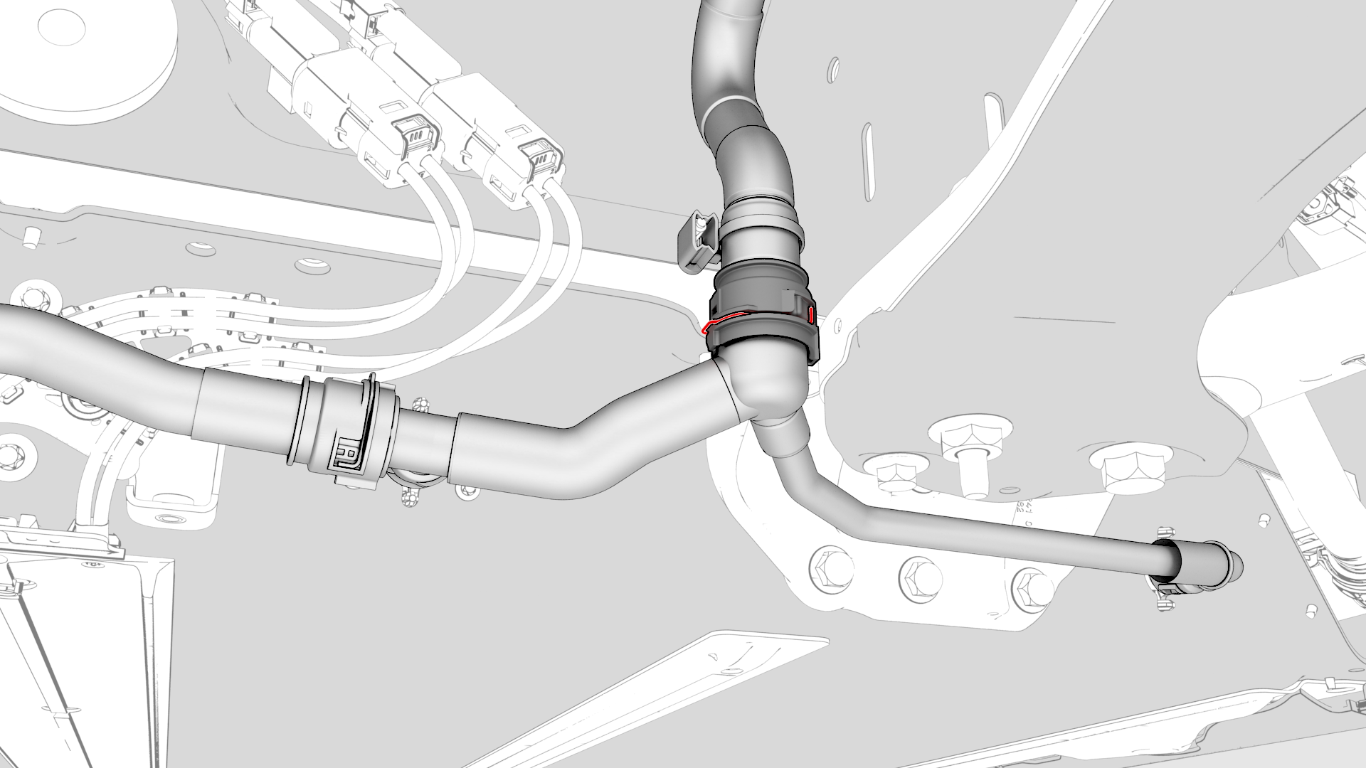
-
Disconnect the HV battery return hose at the LH side of the vehicle and plug the male connector.
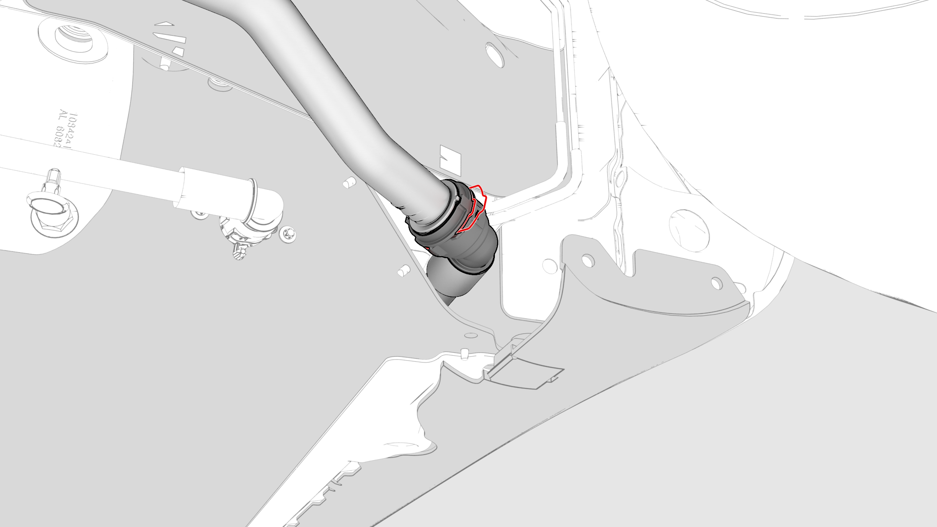
-
Disconnect the battery to chiller hose at the LH side of the vehicle and plug the female connector.
| 1 | Position the coolant drain under the front LH corner of the HV battery. | ||
| 2 | Disconnect the HV battery return hose at the LH side of the vehicle and plug the male connector. | |
| 3 | Attach the drain fitting adapter to the female connector, and position over the coolant drain. | ||
| 4 | Release the clips that attach the battery to chiller hose to the body. | ||
| 5 | Disconnect the battery to chiller hose at the LH side of the vehicle and plug the female connector. | |
| 6 | Attach the pressure fitting adapter to the male connector. | ||
| 7 | Make sure the valve on the pressure regulator is closed and the regulator is set to zero. | ||
| 8 | Attach the coolant pressure tester to the pressure fitting adapter. | ||
| 9 | Attach the compressed air line to the regulator and set the regulator to 20 psi. | ||
| 10 | Open the valve on the drain fitting adapter. | ||
| 11 | Slowly open the valve on the regulator and allow the coolant to drain. | ||
| 12 | Close the valve on the regulator and disconnect the compressed air line from the regulator. | ||
| 13 | Disconnect the drain fitting adapter and pressure fitting adapter from the connectors. | ||
| 14 | Remove the plugs and reconnect these hoses:
| ||
| 15 | Fasten the clips that attach the HV battery to chiller hose to the body. | ||
| 16 | Install the components that were removed to drain the coolant. See Install. |
Install
- Install the lower clips (x3) that attach the lower rear edge of the RH wheel arch liner to the body.
- Install the lower clips (x3) that attach the lower rear edge of the LH wheel arch liner to the body.
- Install the front HV battery skid plate. See Skid Plate - HV Battery - Front (Remove and Replace).
- Perform a penthouse coolant leak test. See Penthouse Coolant Leak Test.
- Refill the system with coolant. See Refill.
| 1 | Install the lower clips (x3) that attach the lower rear edge of the RH wheel arch liner to the body. |
| 2 | Install the lower clips (x3) that attach the lower rear edge of the LH wheel arch liner to the body. |
| 3 | Install the front HV battery skid plate. See Skid Plate - HV Battery - Front (Remove and Replace). |
| 4 | Perform a penthouse coolant leak test. See Penthouse Coolant Leak Test. |
| 5 | Refill the system with coolant. See Refill. |
Refill
- Refill the system with coolant. See Cooling System (Vacuum Refill).
- Install the cabin intake duct assembly. See Duct - Cabin Intake (Remove and Replace).
| 1 | Refill the system with coolant. See Cooling System (Vacuum Refill). |
| 2 | Install the cabin intake duct assembly. See Duct - Cabin Intake (Remove and Replace). |