Harness - Main Front (Remove and Replace)
Correction code 1710070217100702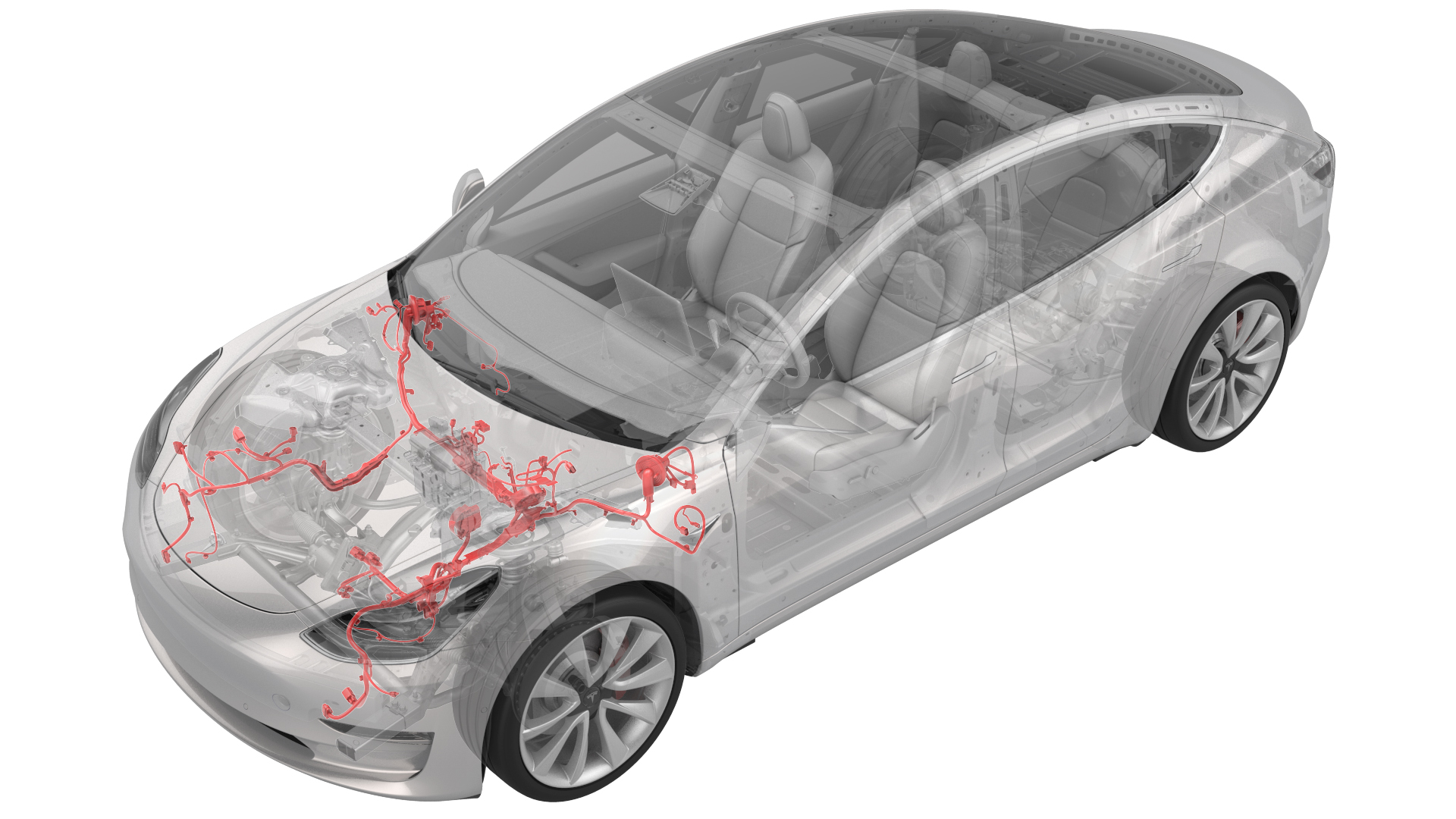
Remove
-
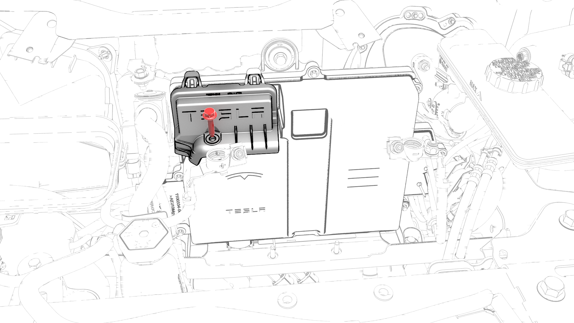
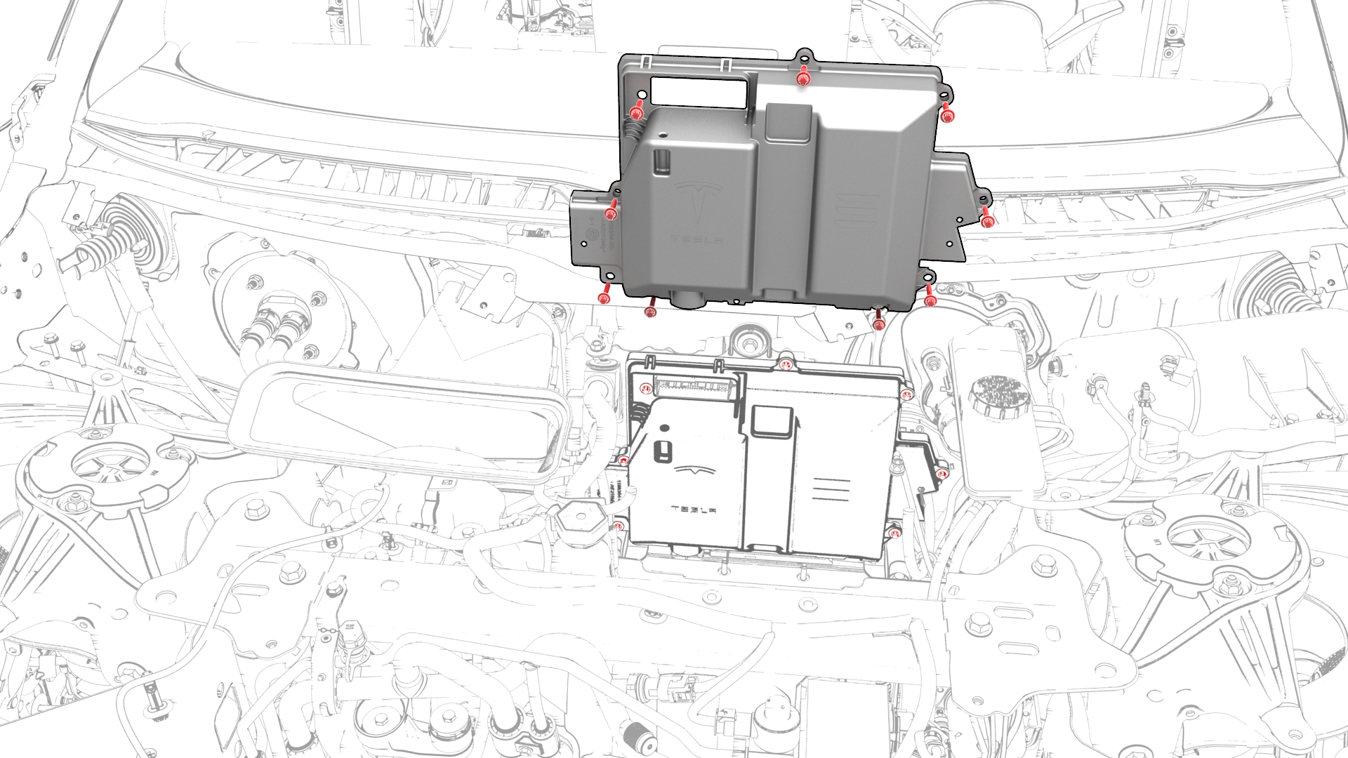
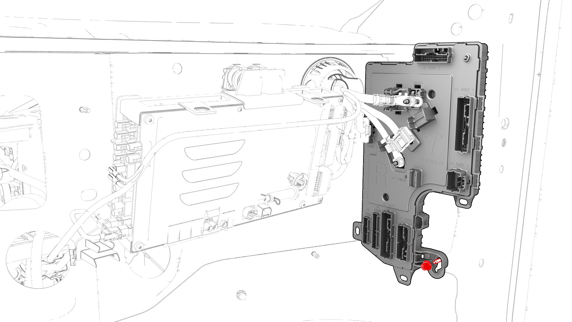
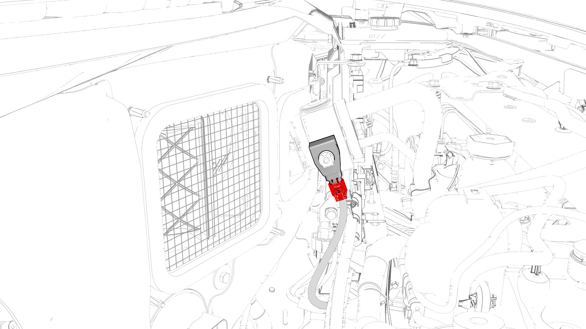
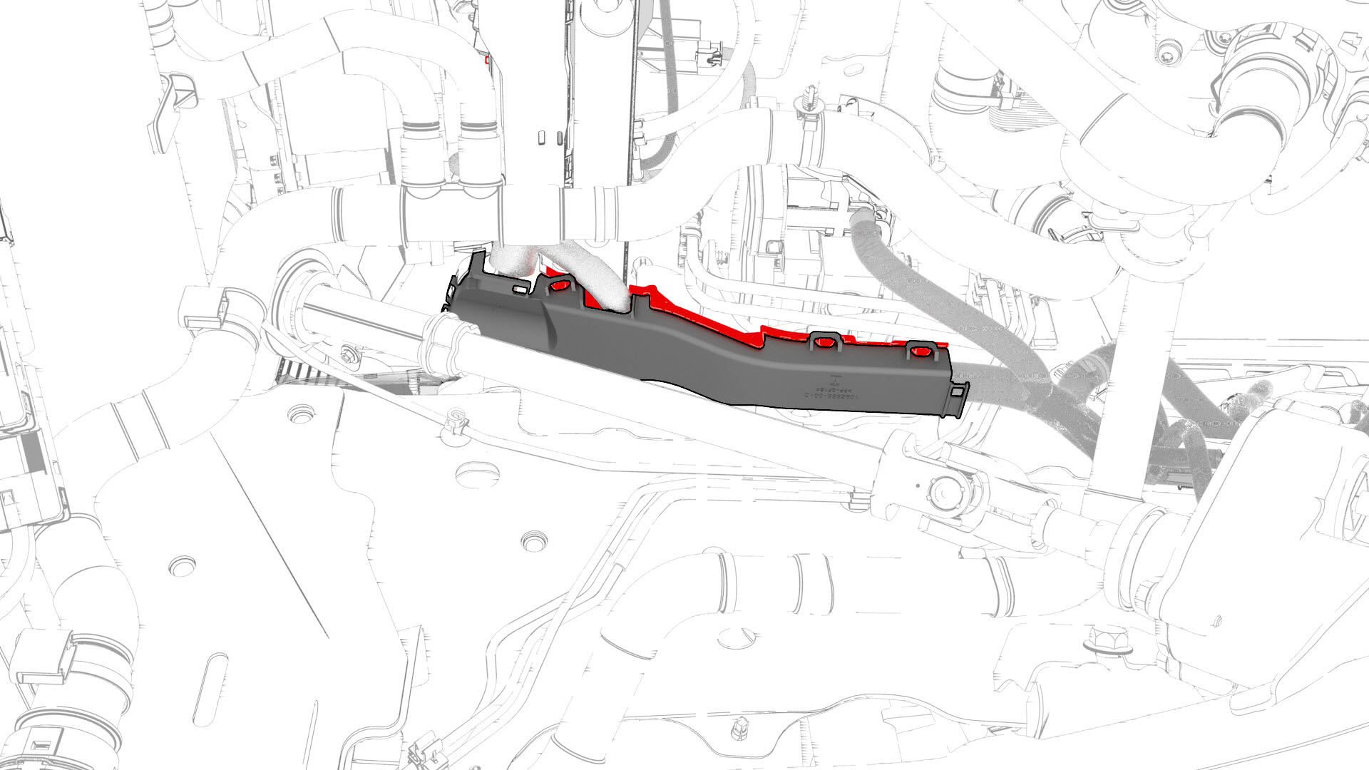
Remove the bolt that attaches the thermal harness cover to the front body controller module, and then remove the cover from the module.
-
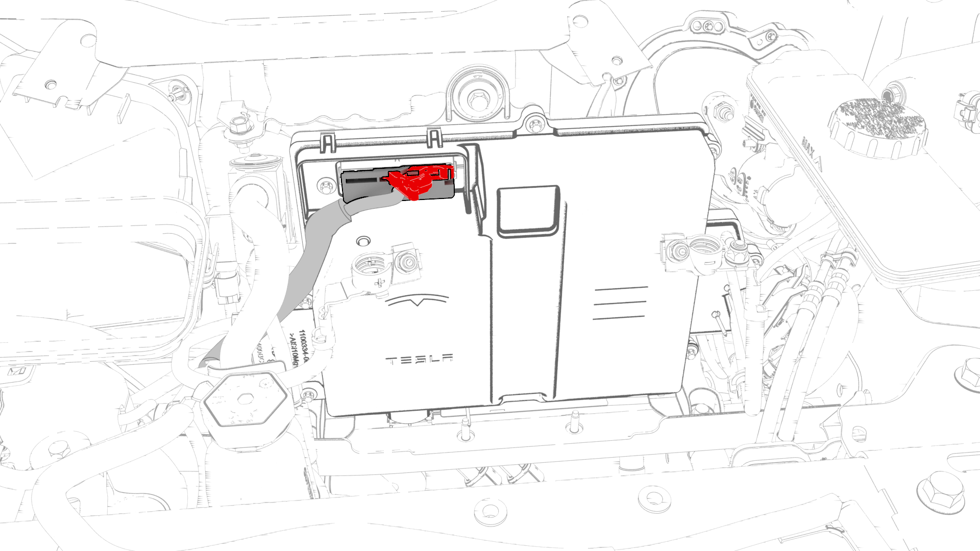
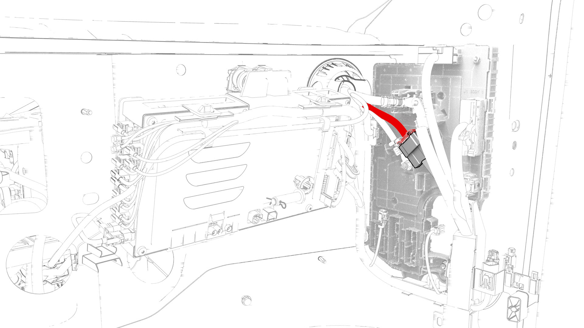
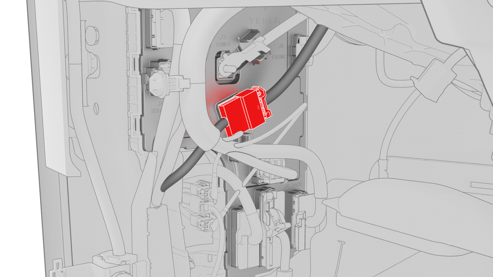
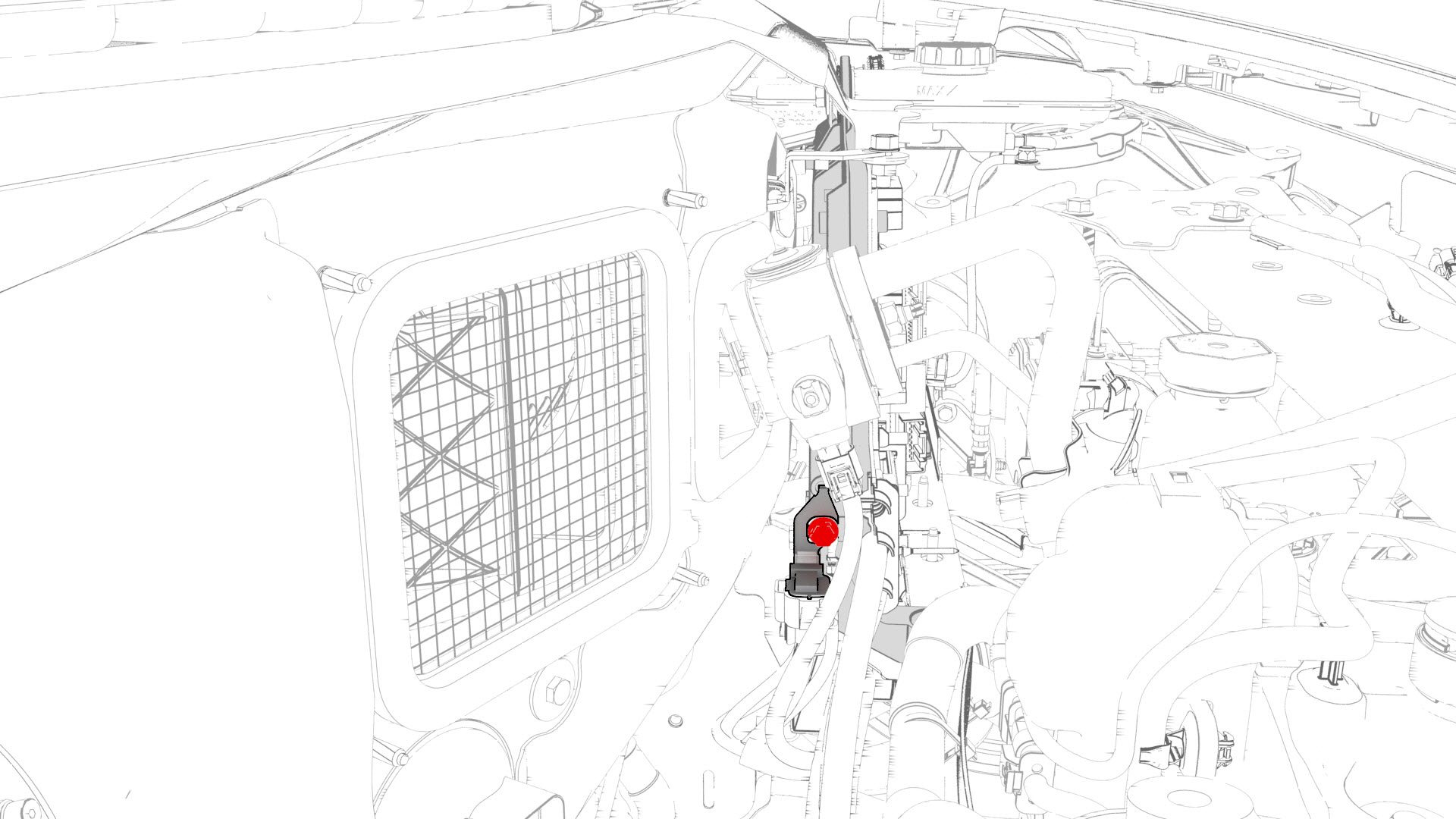
Disconnect the thermal harness from the front body controller module connector.
-
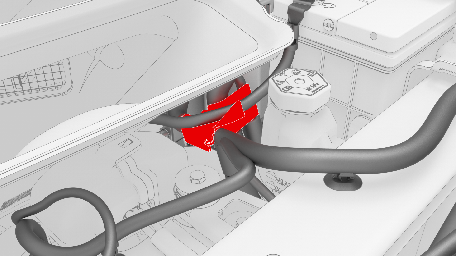
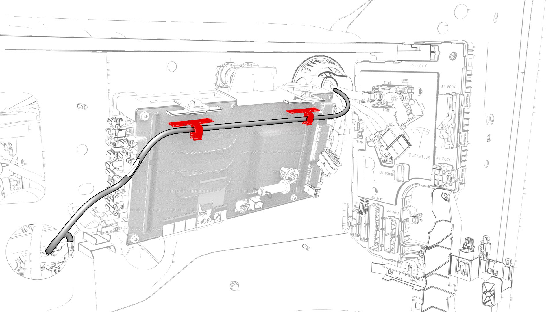
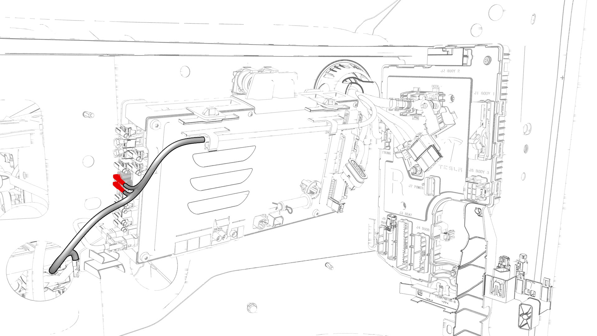
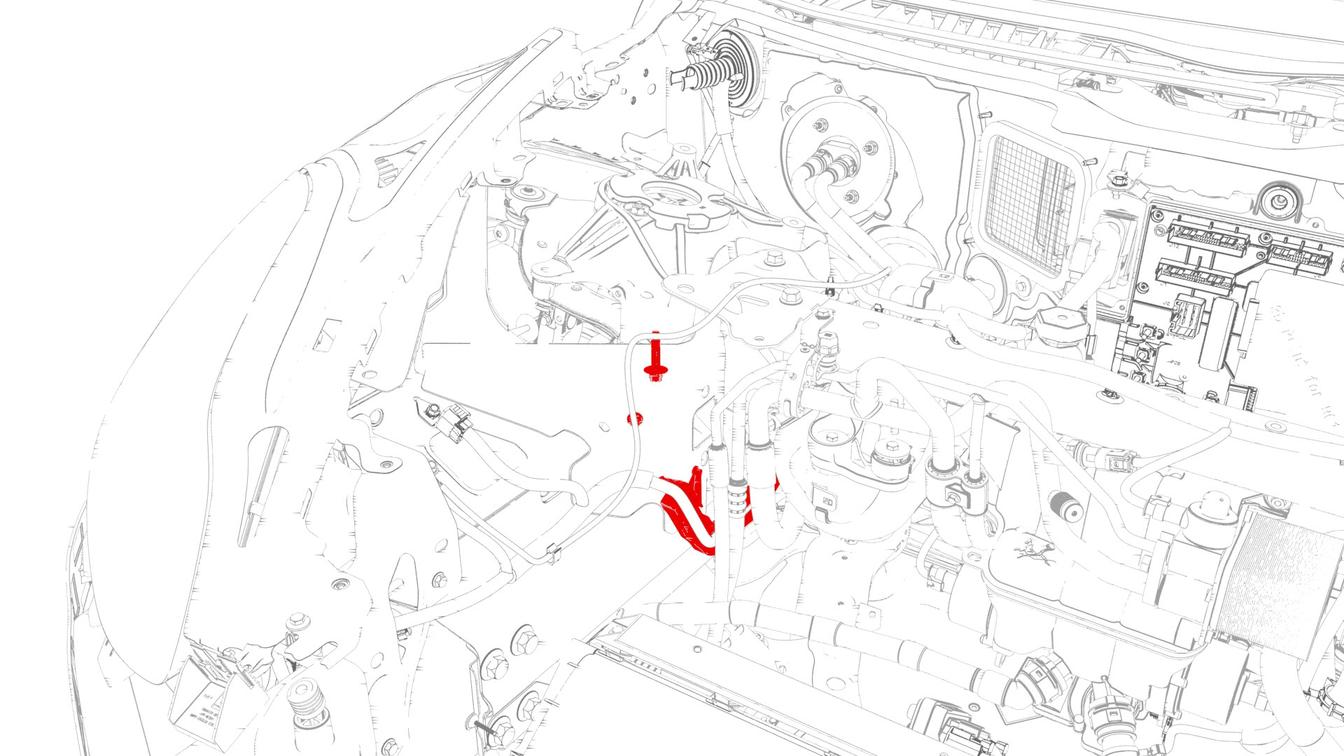
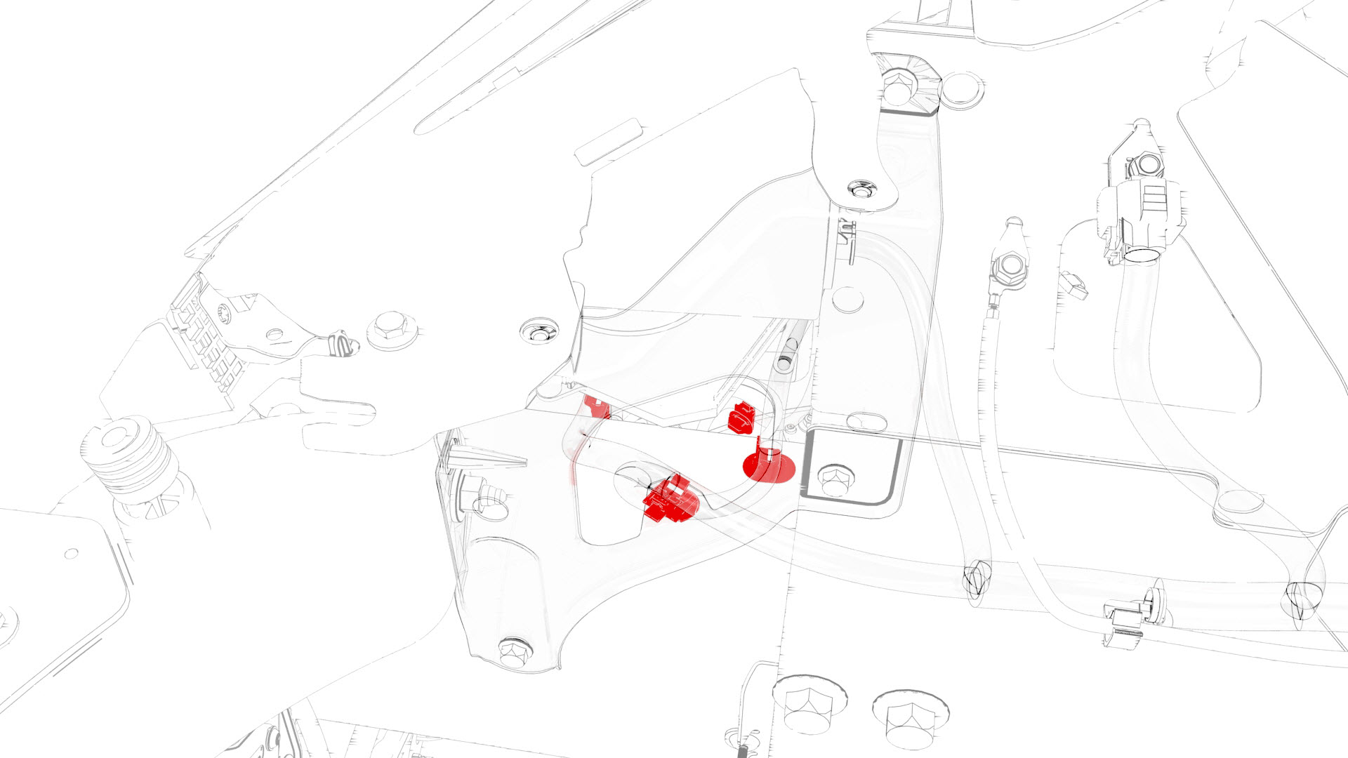
Release the clip that attaches the suction/liquid lines to the body near the TXV, and then move the electrical harness aside to gain access to the front body controller module.
-
Remove the bolts that attach the front body controller module cover to the front body controller module, and then remove the cover.
-
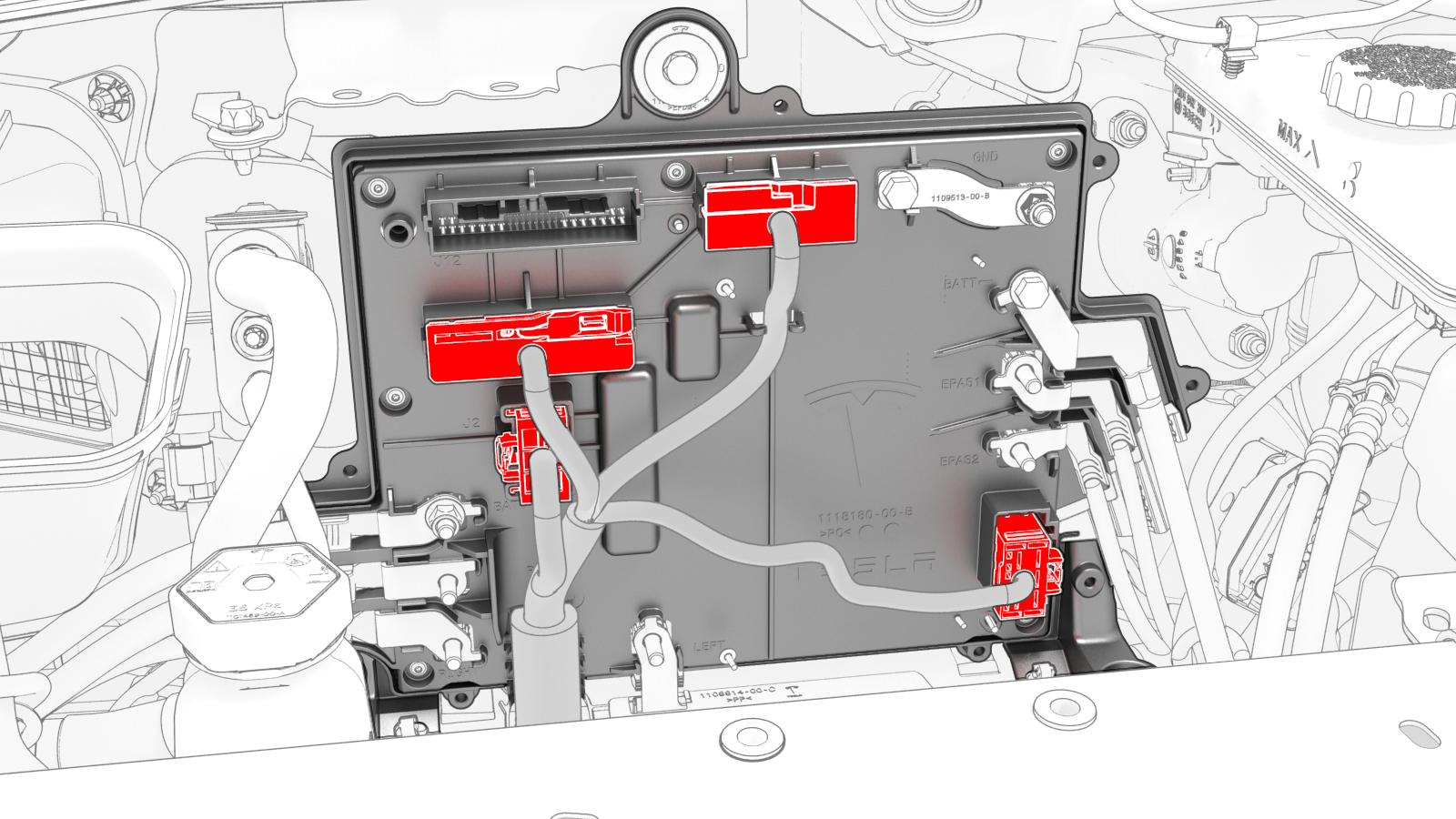
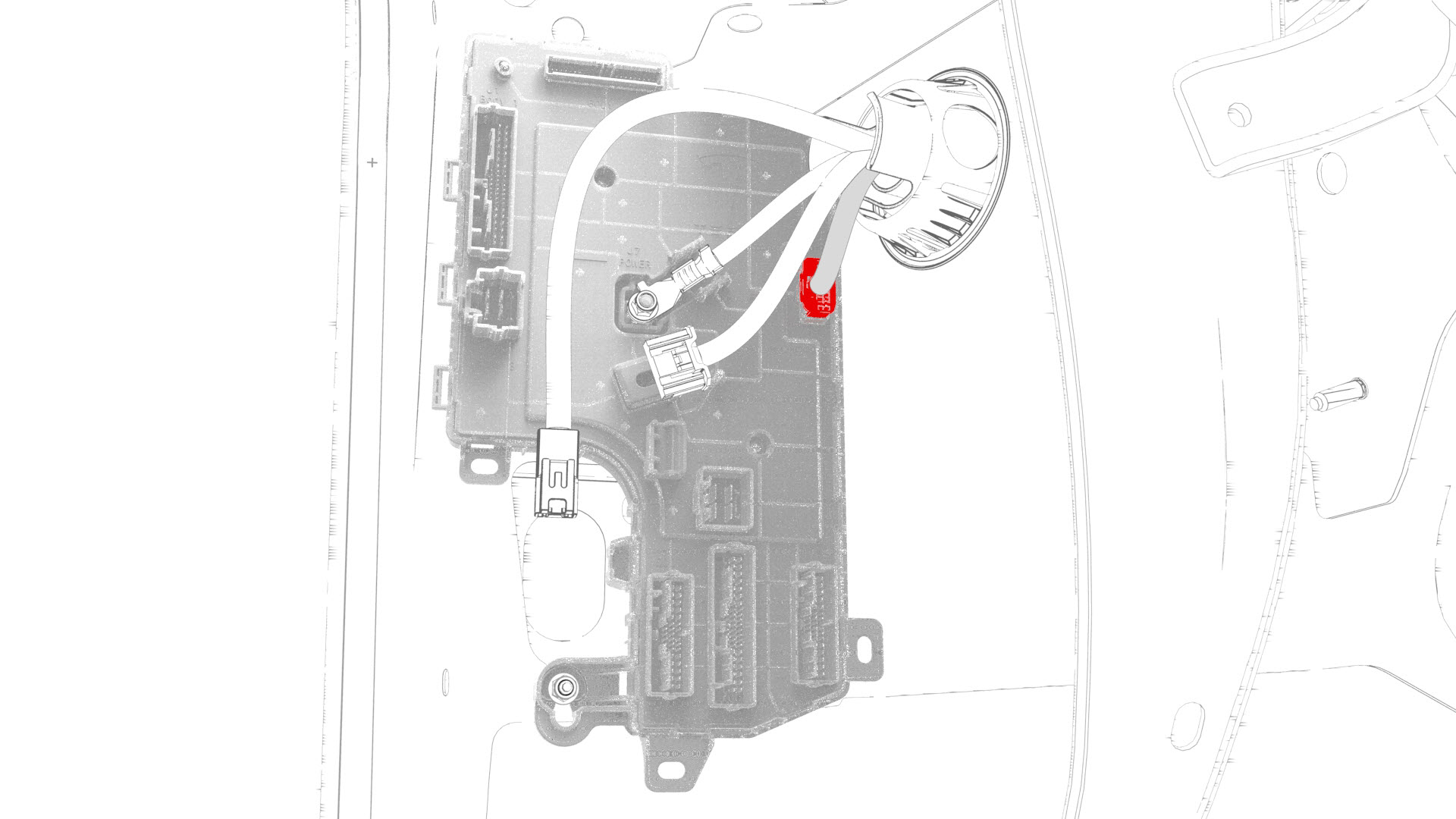
Disconnect the main front harness from the front body controller module connectors.
-
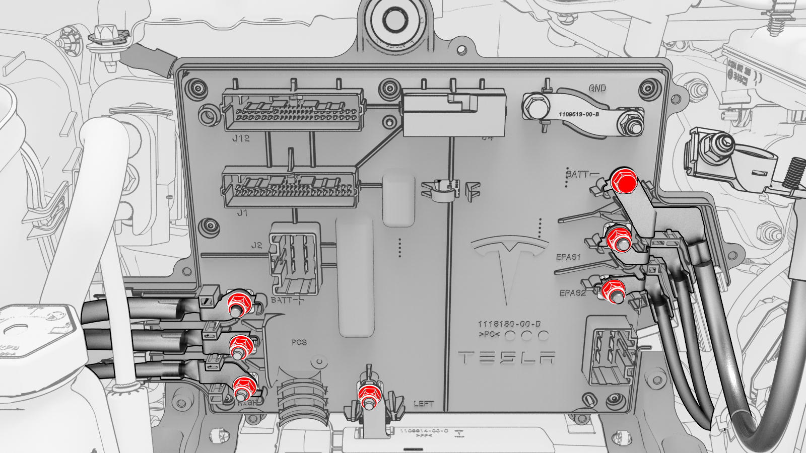
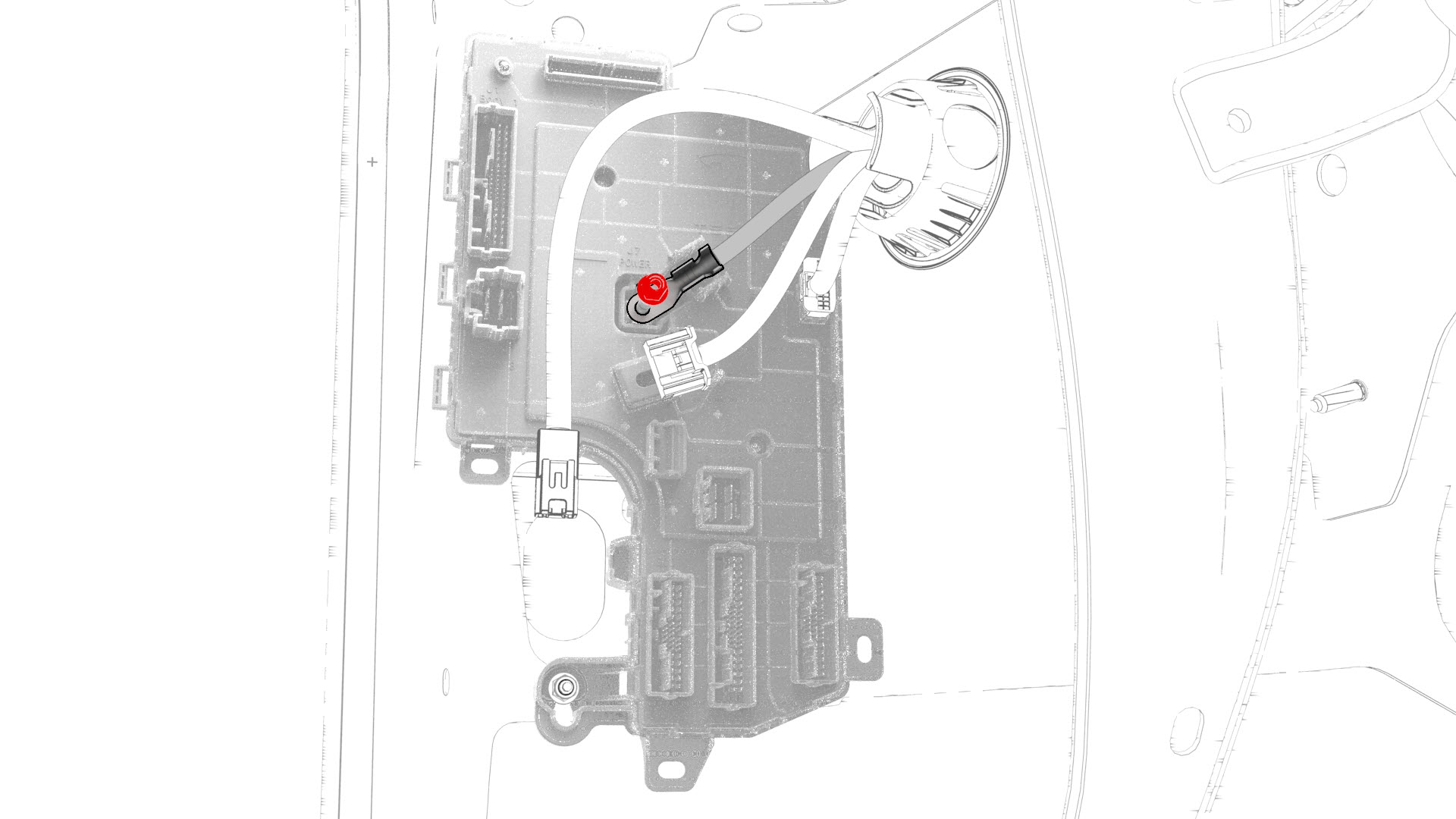
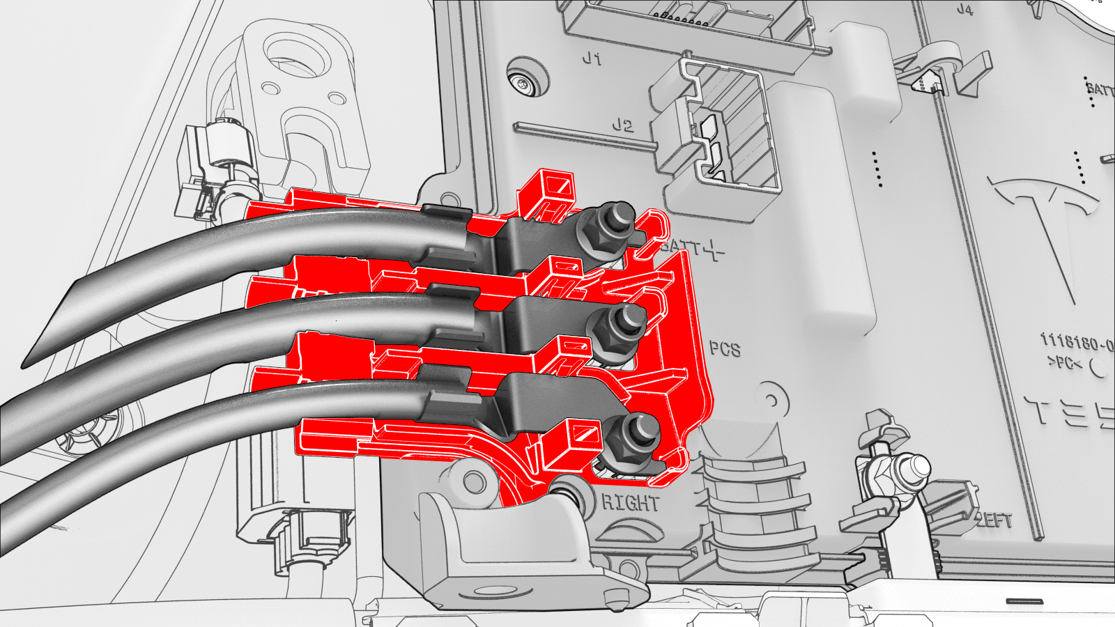
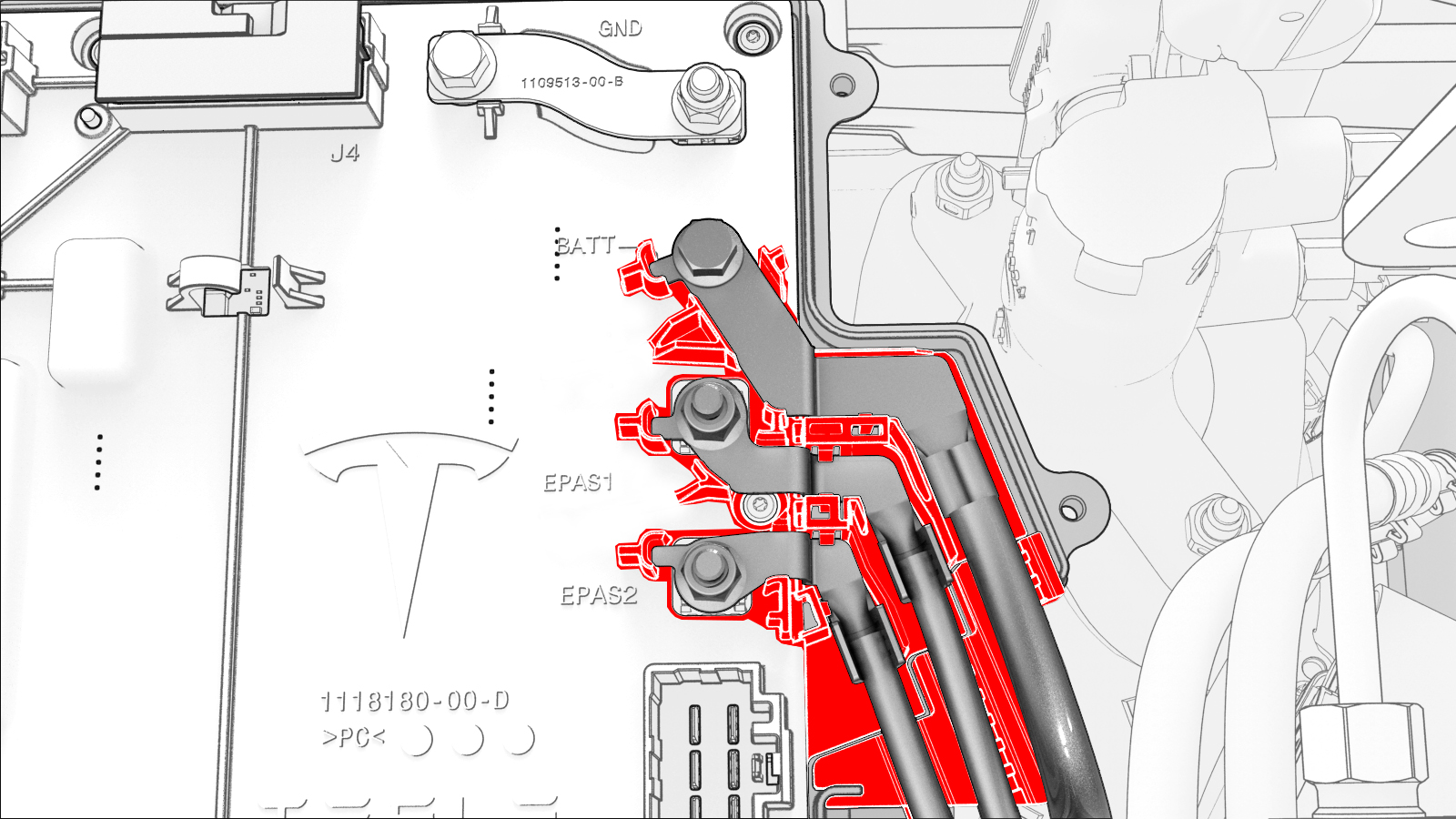
Remove and discard the nuts (x6) and bolt that attach the power and ground cables to the front body controller module.
-
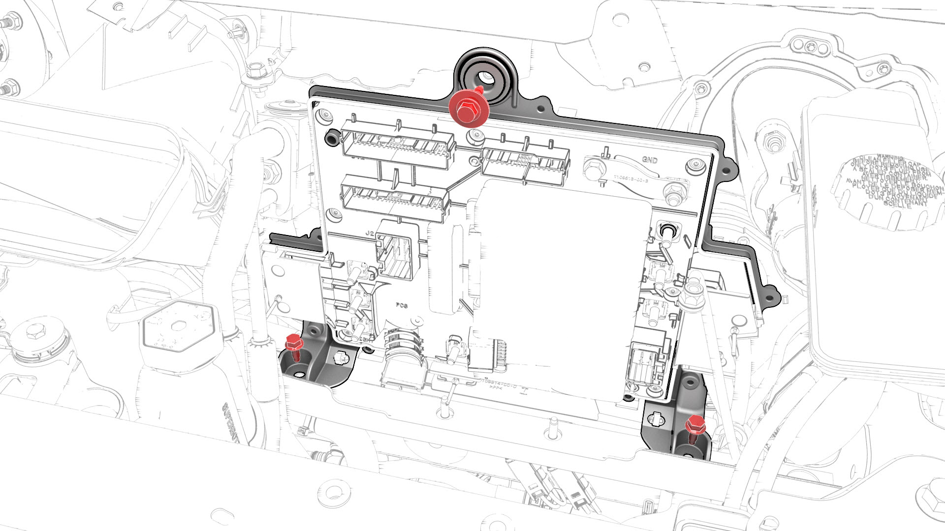
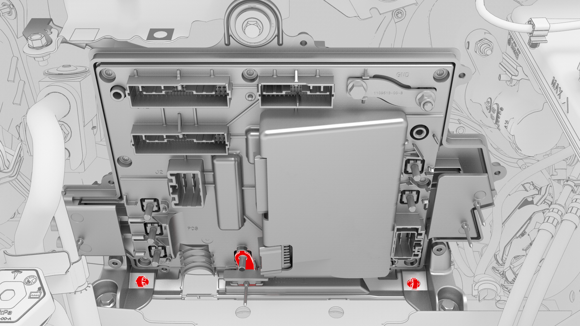
Remove the bolts that attach the front body controller module to the body.
-
Release the clips that attach the bottom of the front body controller module to the body, and then remove the lower busbar from the stud.
-
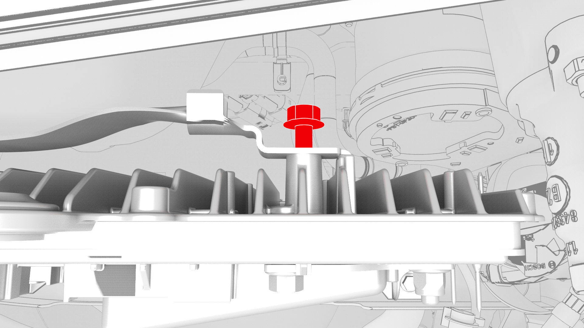
Remove the bolt that attaches the ground strap to the upper rear of the front body controller module, and then remove the ground strap from the module.
-
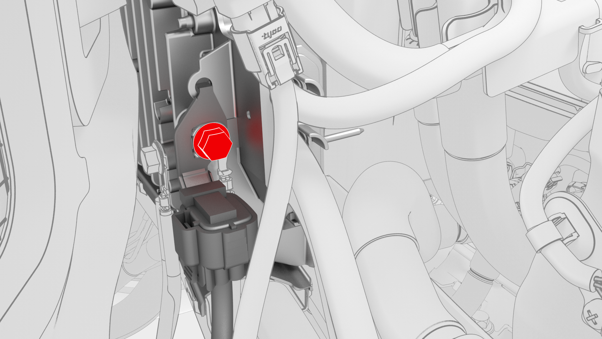
Remove the bolt that attaches the ground strap to the lower right side of the front body controller module, and then remove the ground strap from the module.
-
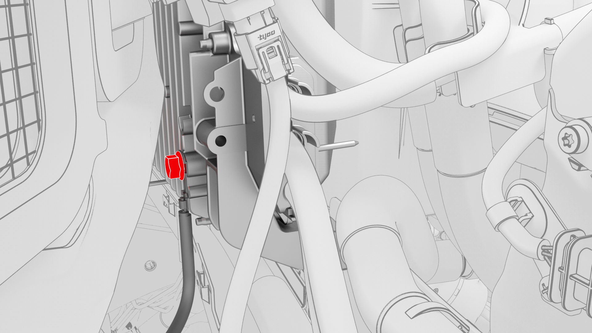
Remove the bolt that attaches the ground strap to the lower rear of the front body controller module, and then remove the module from the vehicle.
-
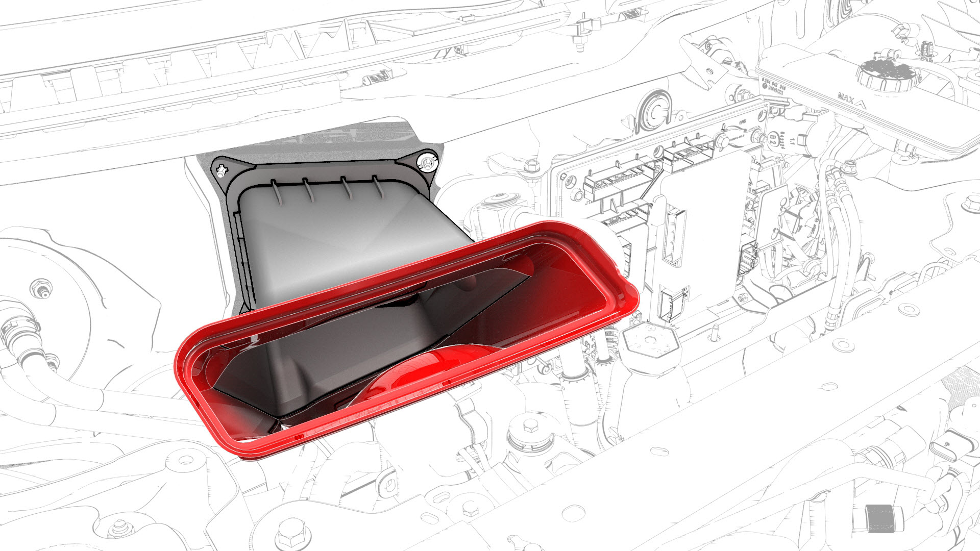
Release the clips that attach the HVAC plenum outer duct to the HVAC plenum inner duct, and then remove the outer duct.
-
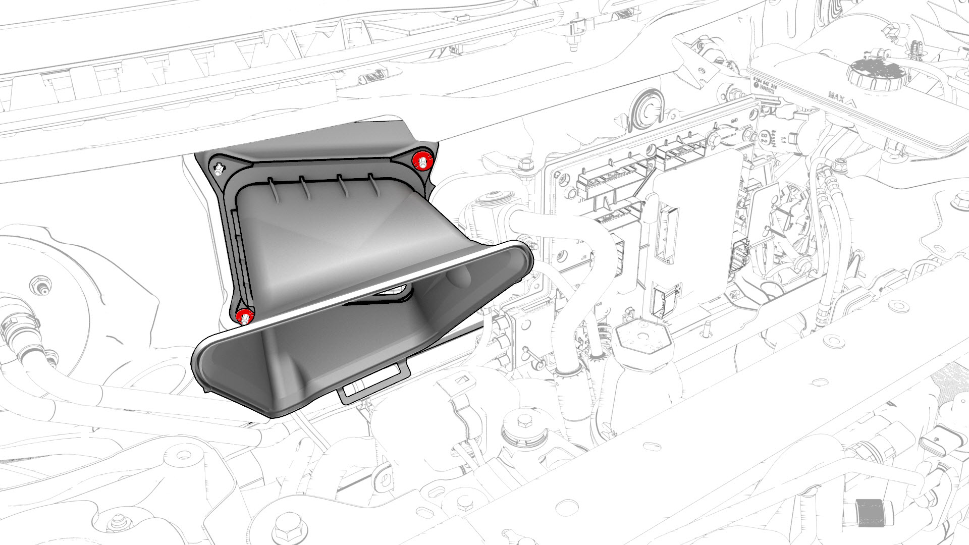
Remove the fasteners that attach the HVAC plenum inner duct to the body, and then remove the inner duct from the vehicle.
-
Disconnect the electrical harness from the RH body controller module connector.
-
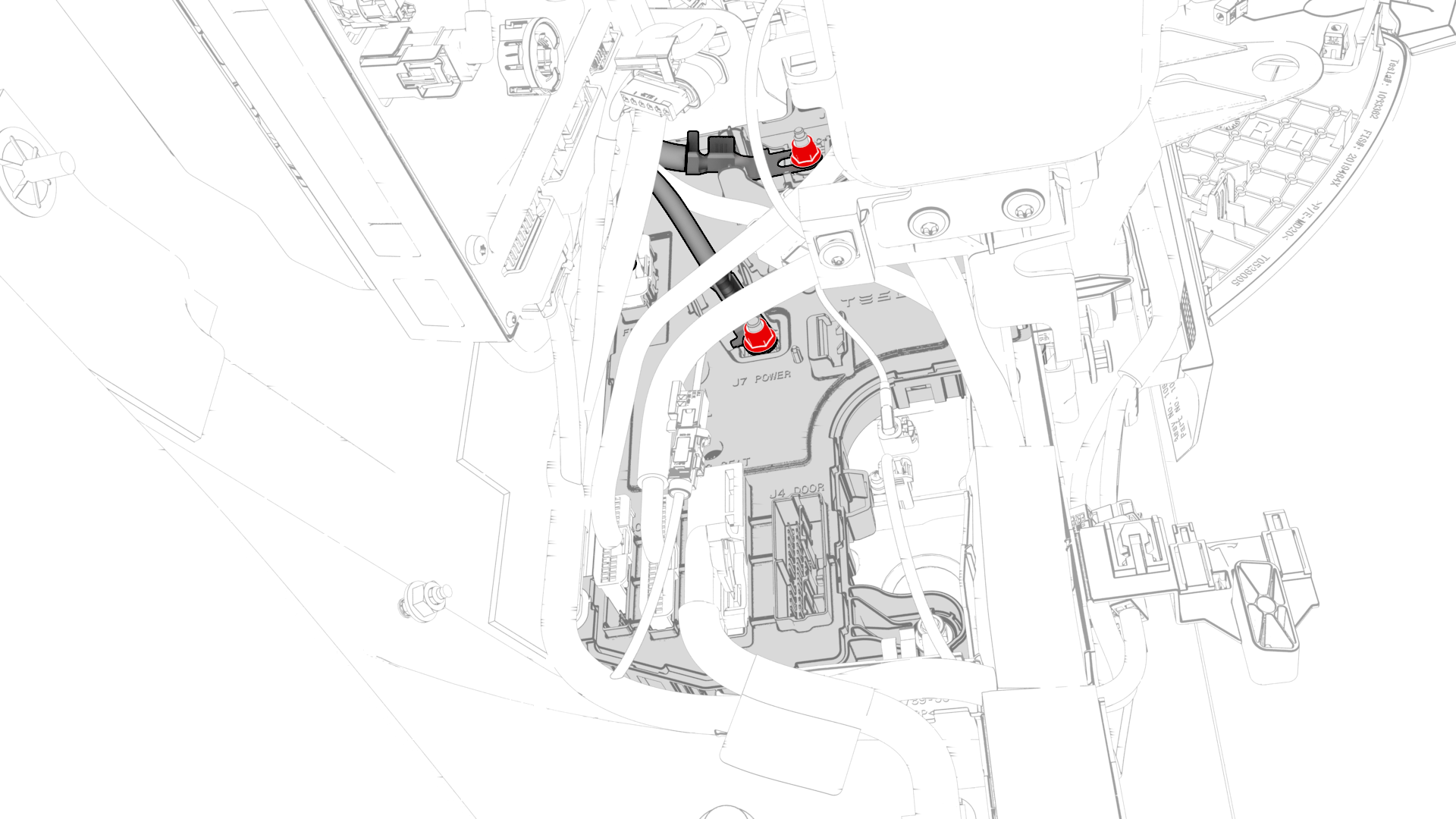
Remove and discard the nuts (x2) that attach the power cables of the electrical harness to the RH body controller module, and remove the power cables from the module.
-
Remove and discard the nut that attaches the RH body controller module to the A-pillar, and lower the module for access.
-
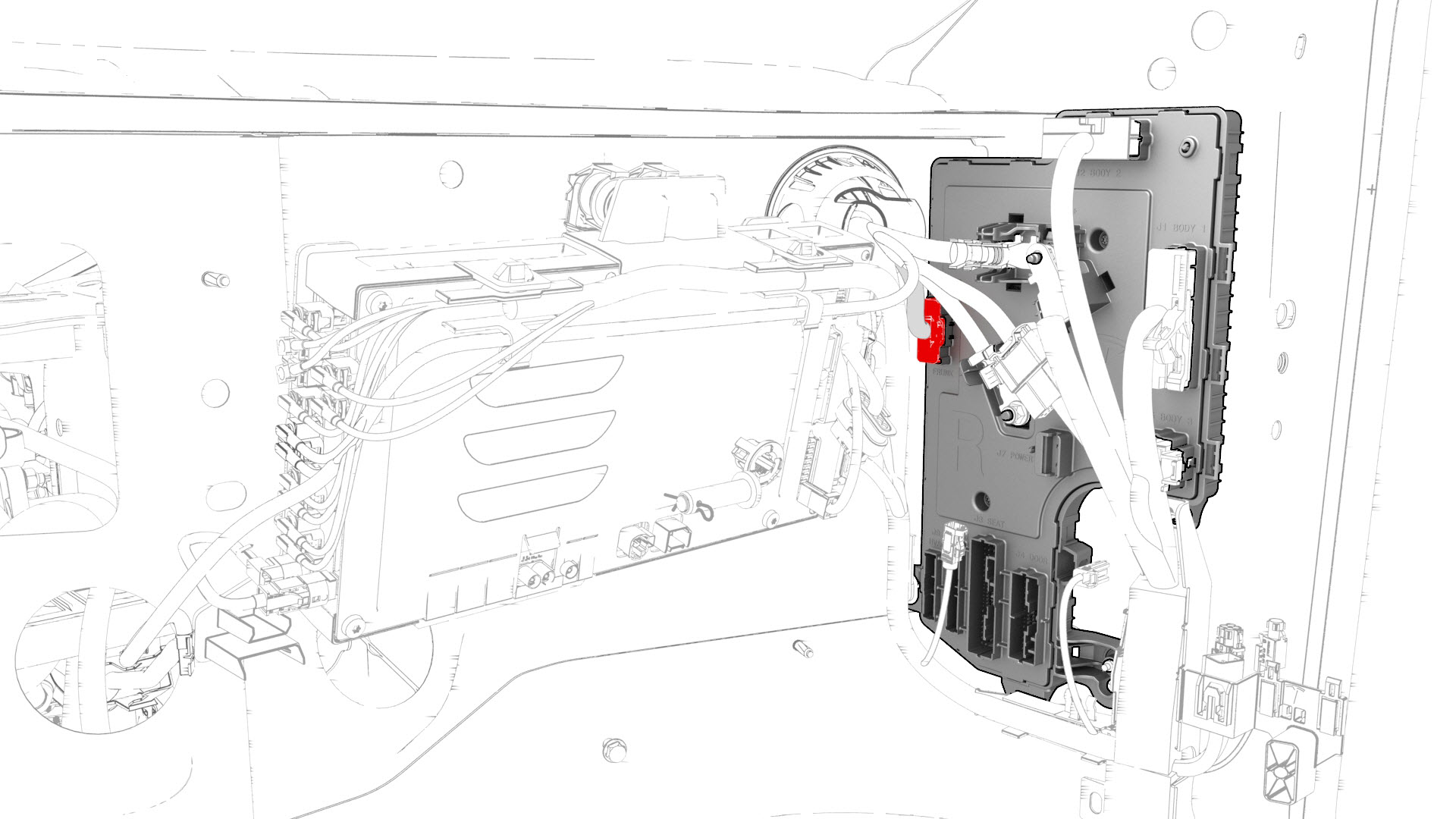
Release the clip that attaches the inline electrical harness connector to the RH body controller module, and then disconnect the electrical connector.
-
Release the clips that attach the electrical harness to the car computer.
-
Disconnect the electrical harness from the car computer connectors (x7).
-
Disconnect the electrical harness from the LH body controller module connector.
-
Remove and discard the nut that attaches the power cable of the electrical harness to the LH body controller module, and remove the power cable from the module.
-
Release the clip that attaches the inline electrical harness connector X909 to the LH body controller module, and then disconnect the electrical connector.
-
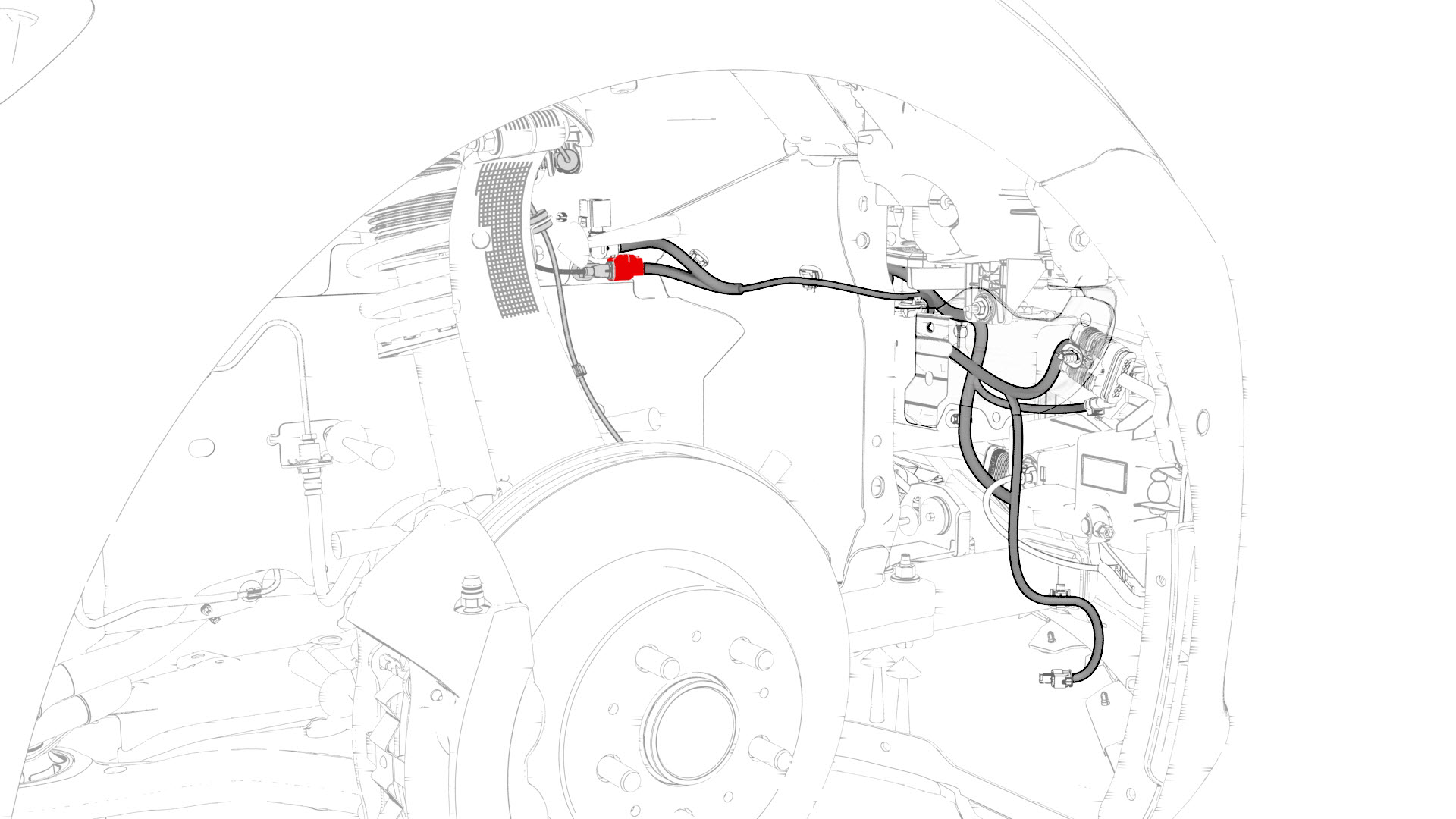
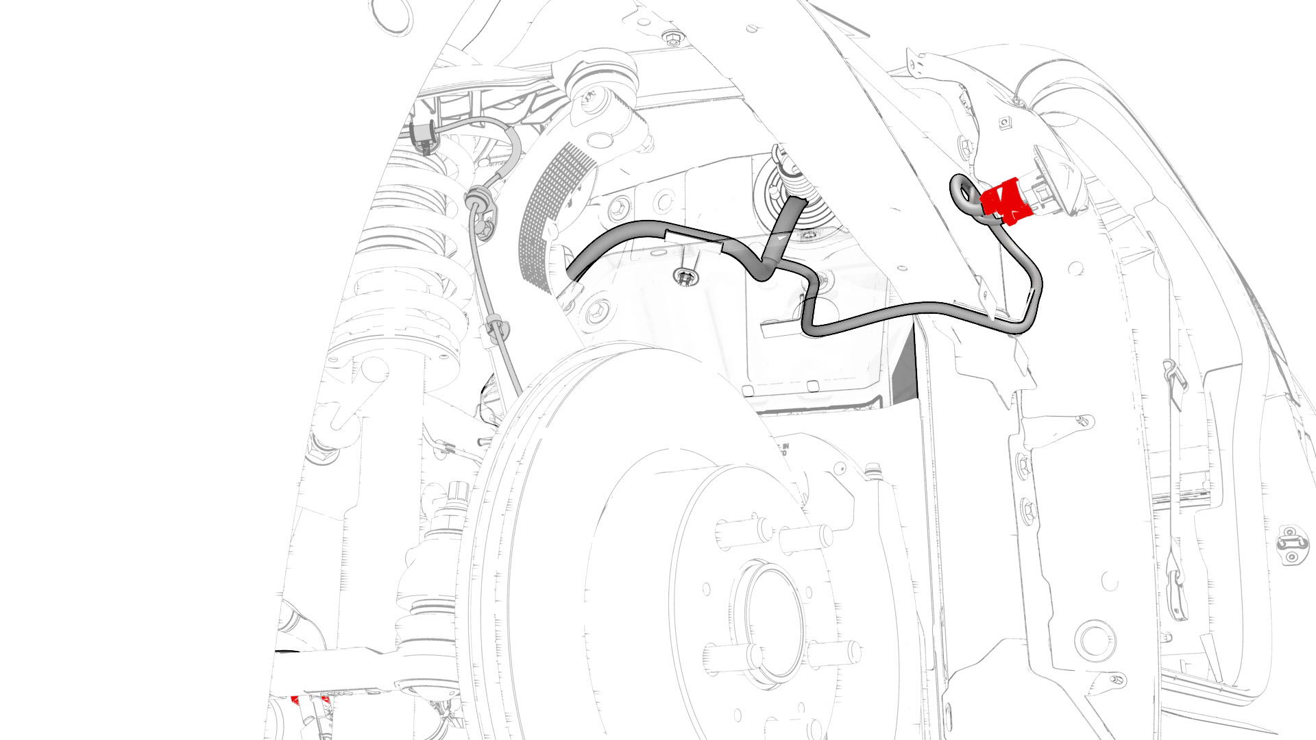
Release the clip that attaches the electrical harness to the body in the brake booster area.
-
Disconnect the electrical harness from the connectors (x3) in the brake booster area.
-
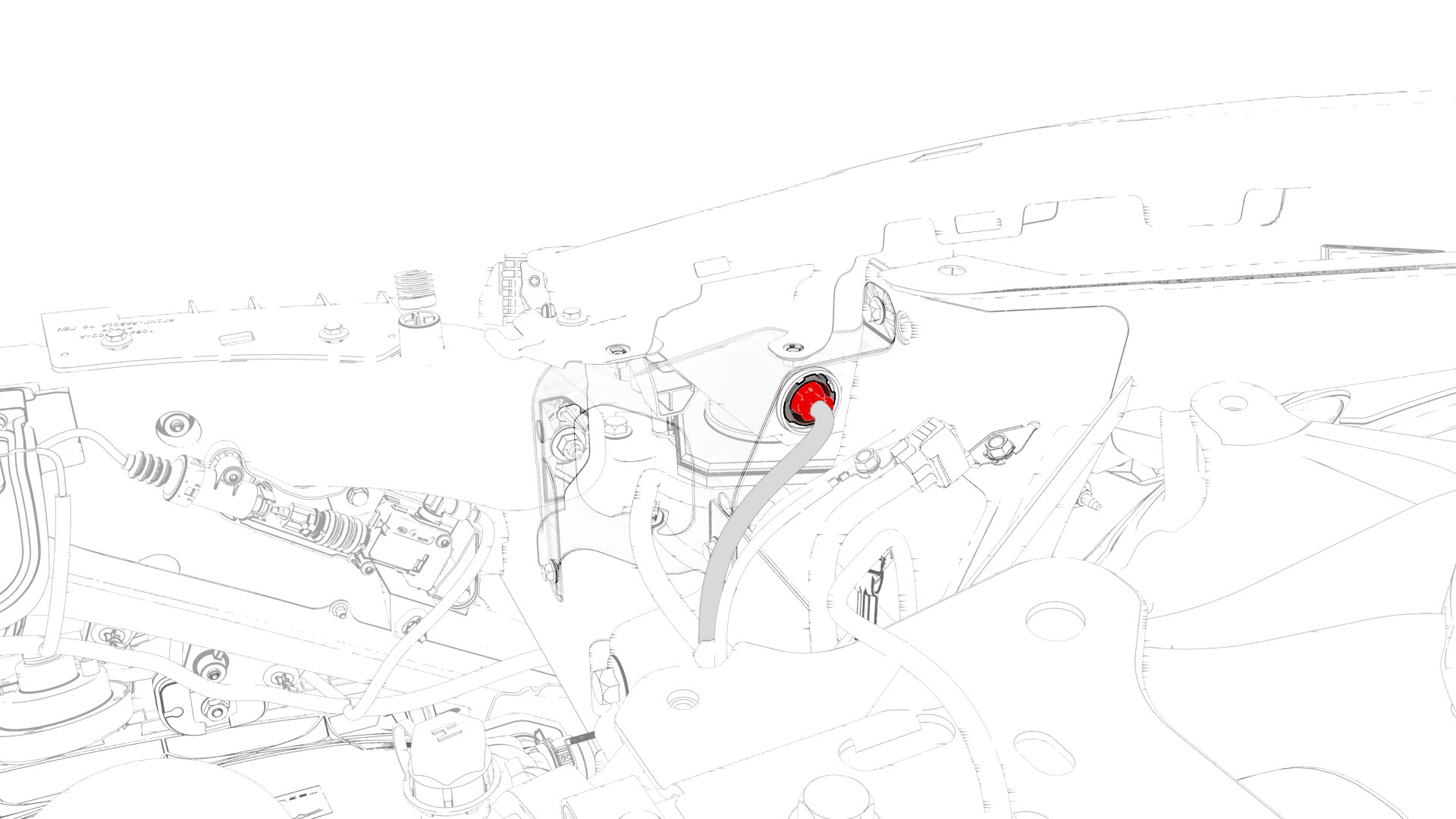
Disconnect the electrical harness from the brake booster connector.
-
Disconnect the electrical harness from the ABS unit connector.
-
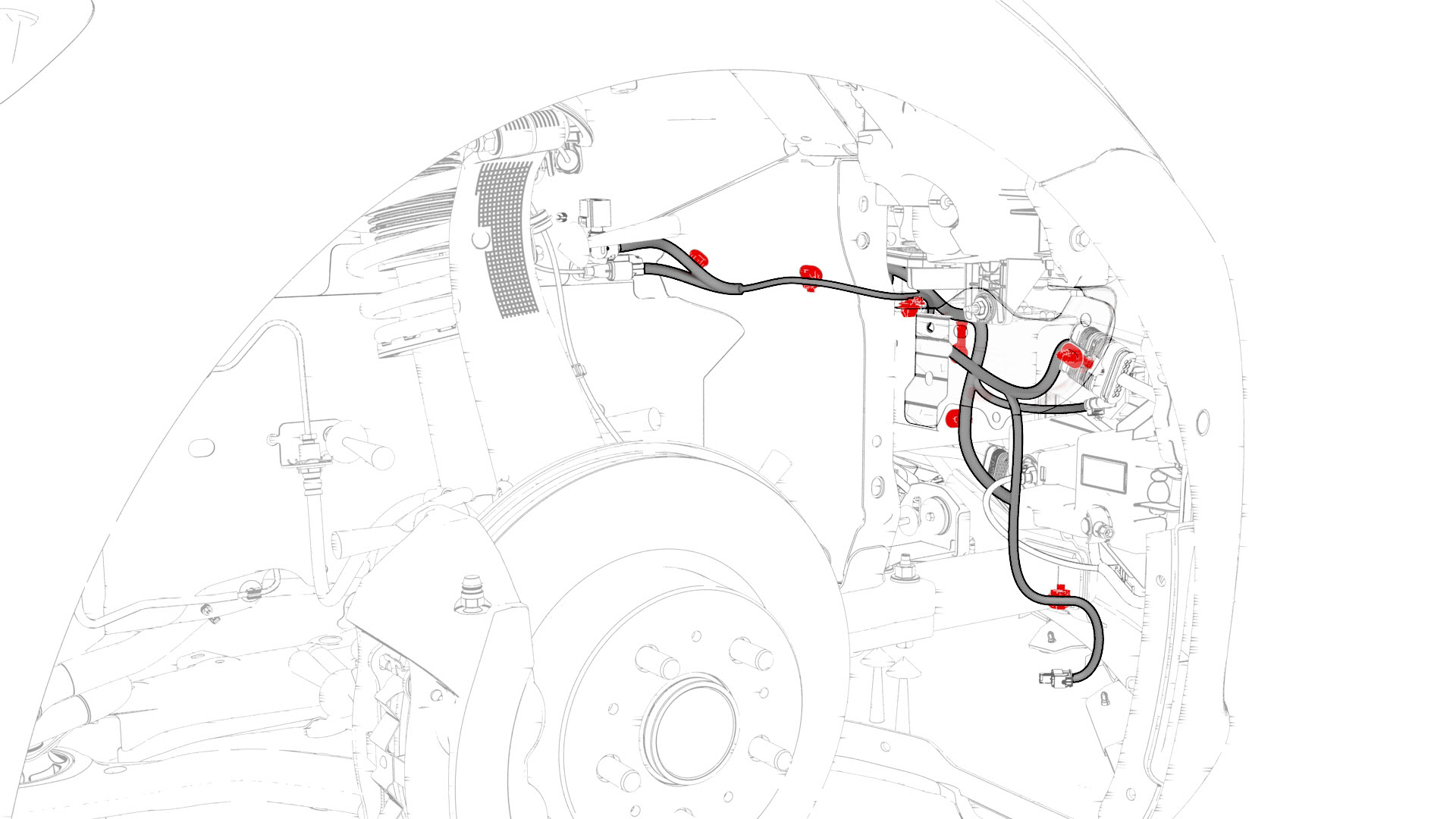
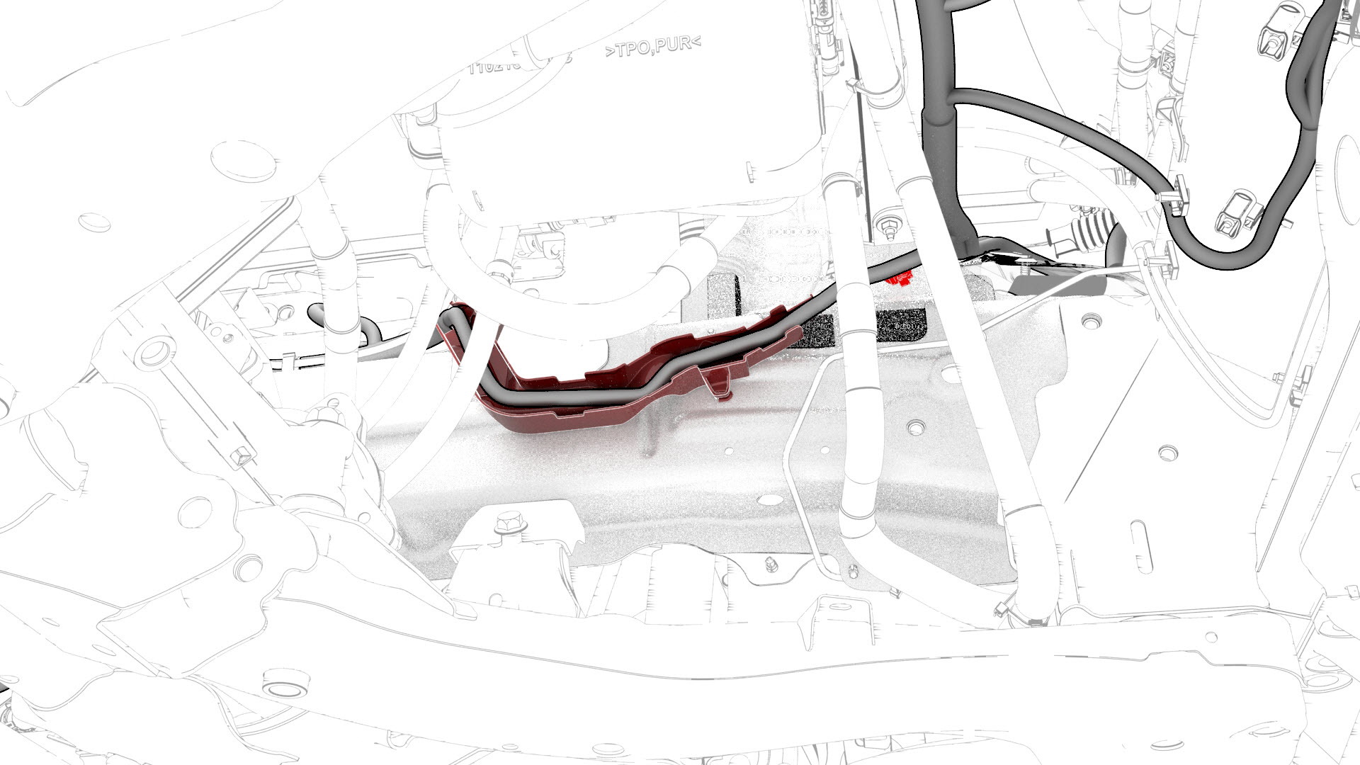
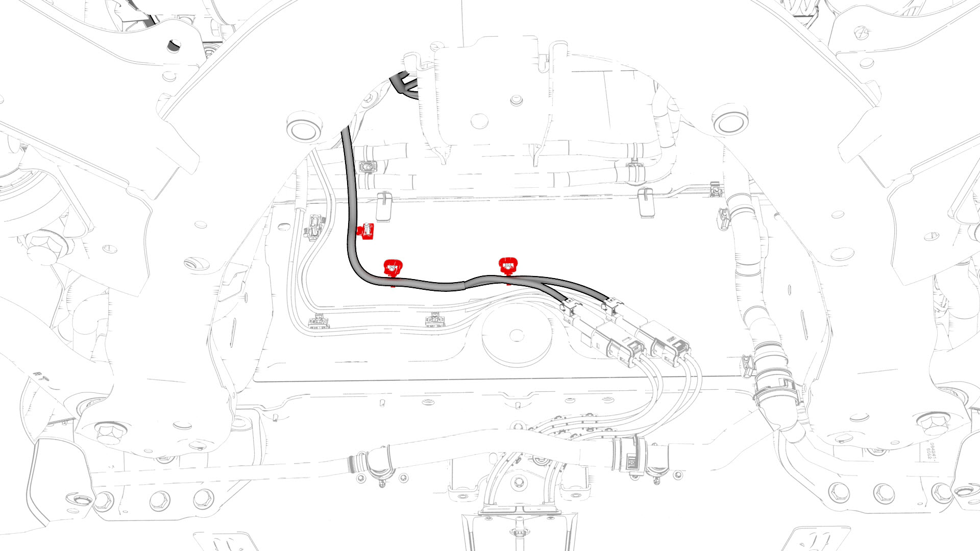
Release the clips that attach the electrical harness to the body in the front LH frame rail area.
-
Remove and discard the bolts (x4) that attach the electrical harness ground terminals to the body in the front LH frame rail area.
-
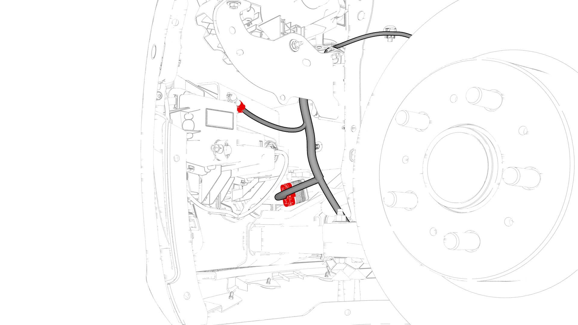
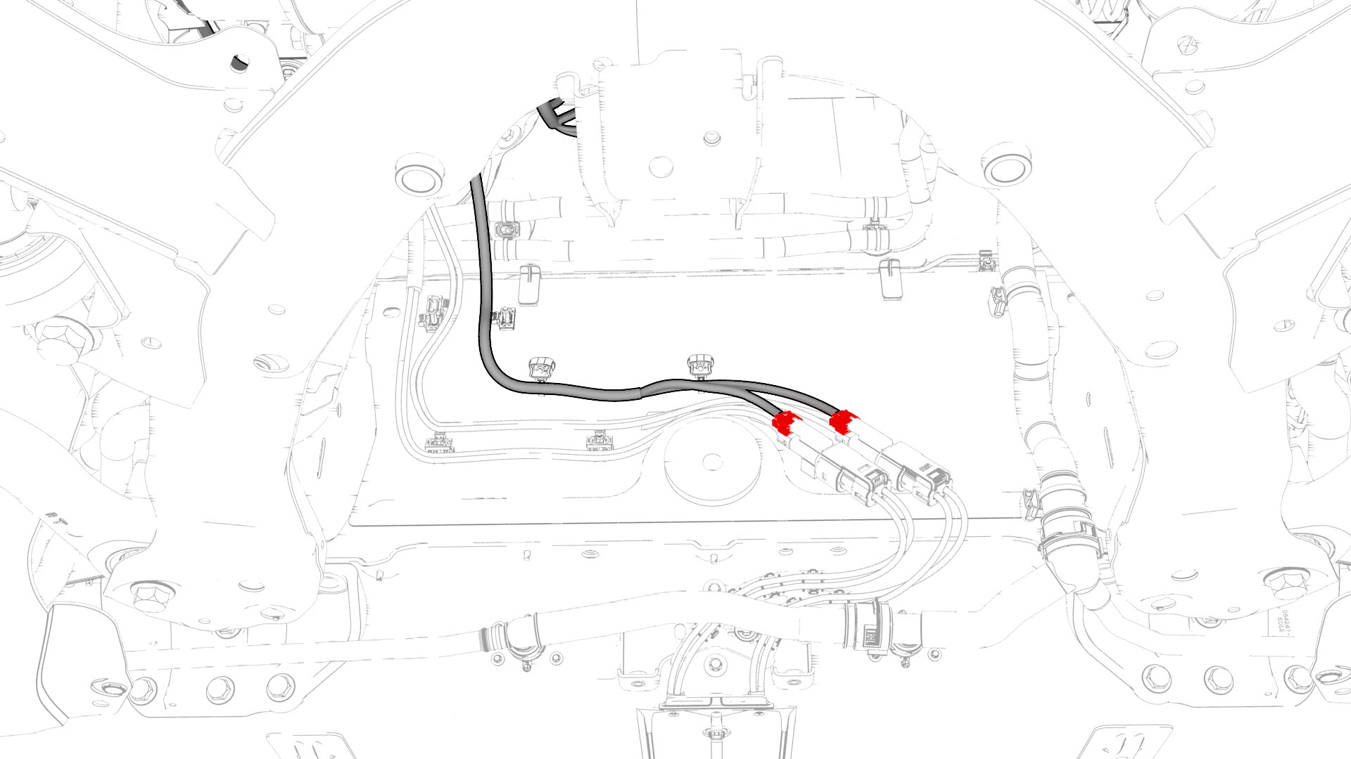
Disconnect the electrical harness from the steering rack connectors and connectors in the front LH frame rail area.
-
Disconnect the electrical harness from the LH headlight connector.
-
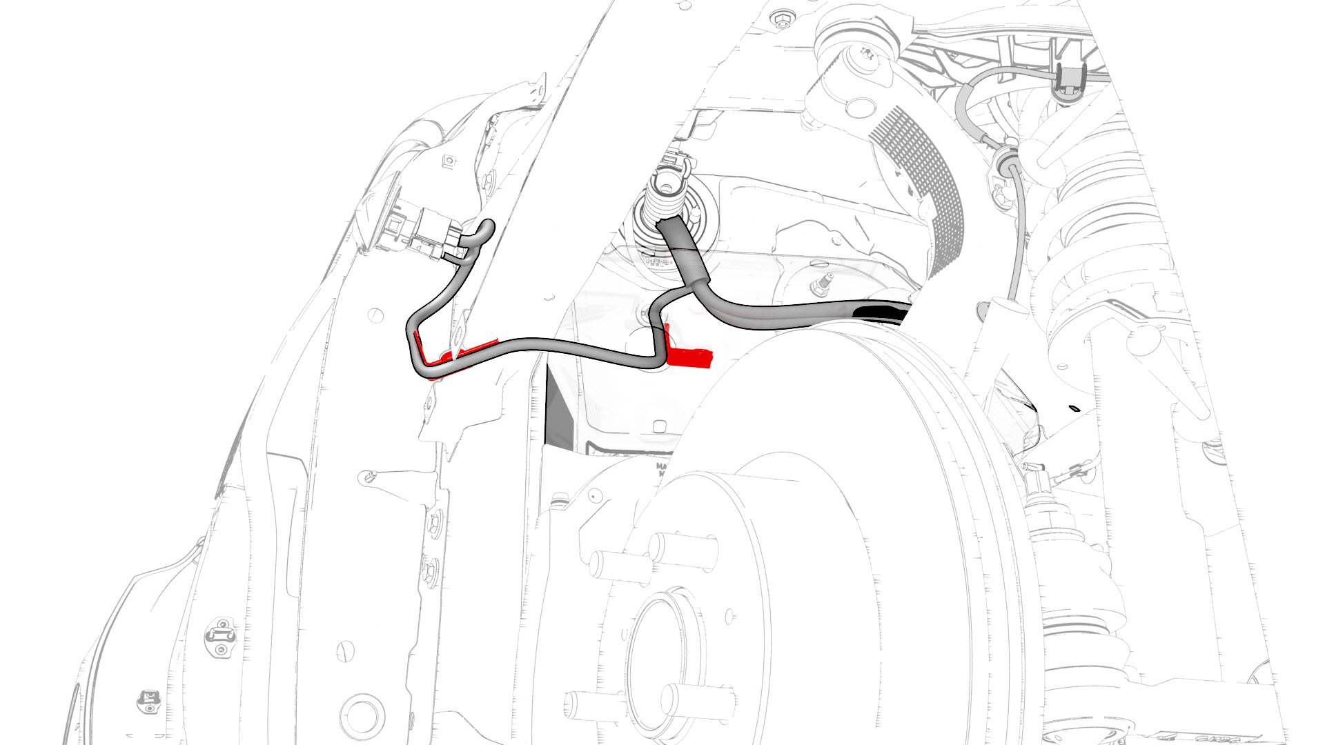
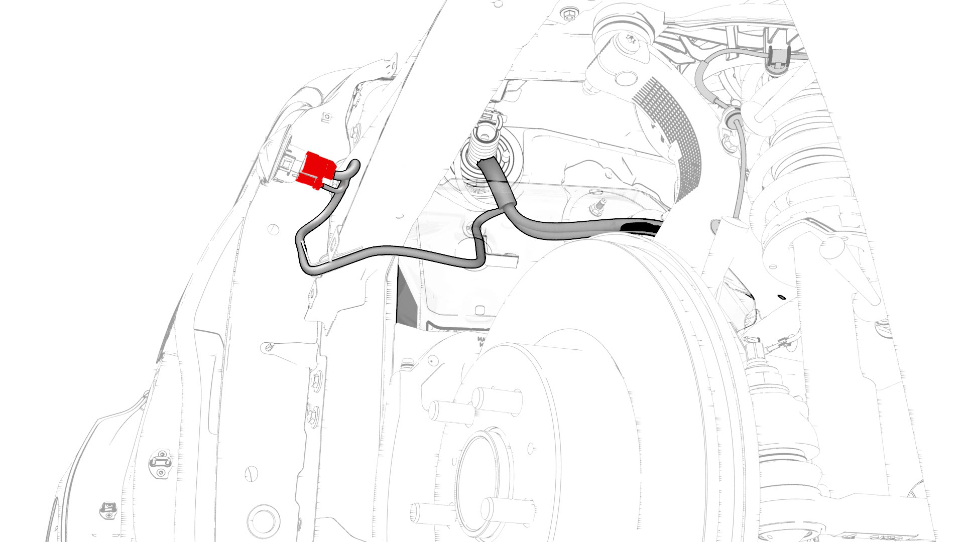
Release the clips that attach the electrical harness to the body in the HVAC plenum duct area.
-
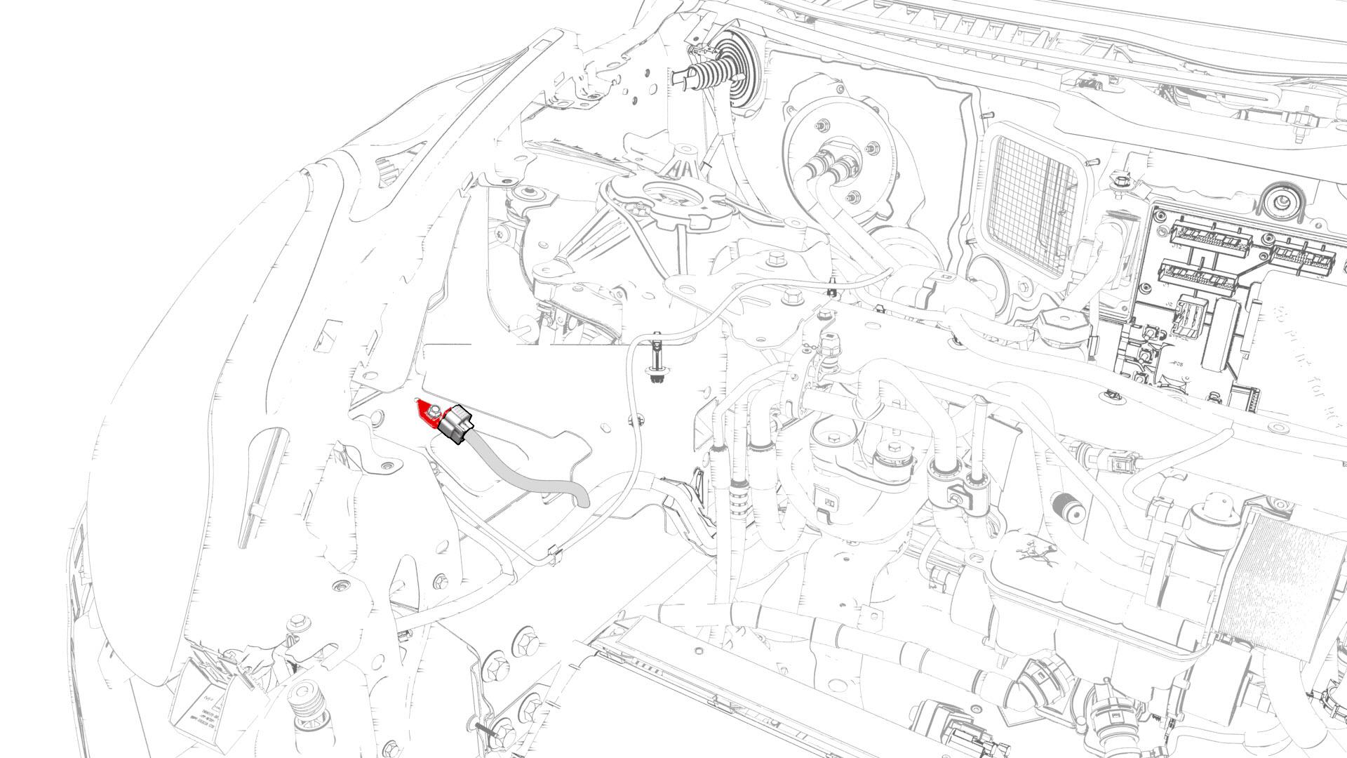
Disconnect the electrical harness from the TXV connector.
-
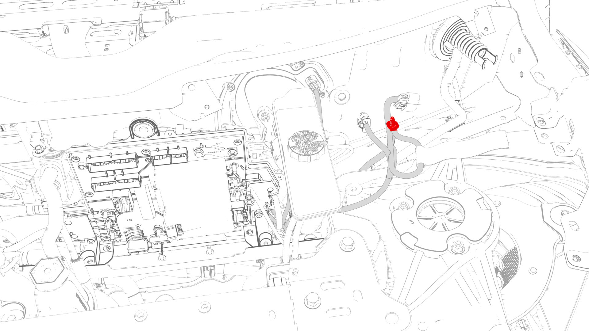
Remove the bolt that attaches the electrical harness ground terminal to the body in the TXV area
-
Release the clips that attach the electrical harness to the body in the front RH frame rail area.
-
Remove and discard the bolt that attaches the electrical harness ground terminal to the body in the front RH frame rail area.
-
Release the clips that attach the electrical harness to the body in the RH headlight area.
-
Disconnect the electrical harness from the RH headlight connector.
-
With an assistant, move the vehicle to a lift.
 Caution:The vehicle is safely pushed for only a very short distance and at a very slow speed.
 -
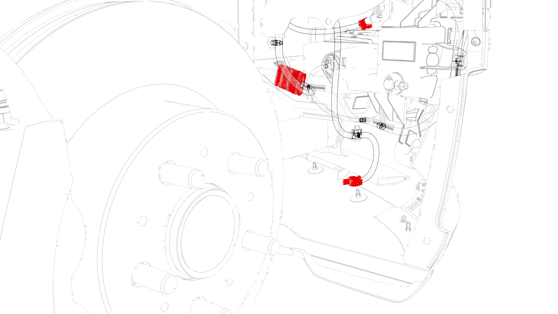
Disconnect the electrical harness from the connectors in the front RH fascia area.
-
Release the clips that attach the electrical harness to the body at the front of the front RH wheel liner area.
-
Disconnect the electrical harness from the connector at the front of the front RH wheel liner area.
-
Release the clips that attach the electrical harness to the body at the rear of the front RH wheel liner area.
-
Disconnect the electrical harness from the front RH side repeater lamp connector.
-
Disconnect the electrical harness from the connectors in the front LH fascia area.
-
Disconnect the electrical harness from the front end module connector.
-
Release the clips that attach the electrical harness to the body in the front LH wheel liner area.
-
Disconnect the electrical harness from the connectors at the front of the front LH wheel liner area.
-
Release the clips that attach the electrical harness to the body in the front LH wheel area.
-
Disconnect the electrical harness from the front LH side repeater lamp connector.
-
Release the clips that attach the electrical harness to the body in the front RH frame area.
-
Release the clips that attach the electrical harness to the body in the bulkhead area.
-
Disconnect the electrical harness from the connectors in the bulkhead area.
-
Release the clips that attach the electrical harness to the body in the LH frame rail area.
-
Remove the electrical harness from the vehicle.
| 1 | Open the front LH and front RH doors. | ||
| 2 | Open the hood. | ||
| 3 | Place wheel chocks on both rear wheels. | ||
| 4 | Put vehicle in Neutral. | ||
| 5 | Disconnect 12V power. See 12V Power (Disconnect and Connect). | ||
| 6 | Remove the LH lower A-pillar trim. See Trim - A-Pillar - Lower - LH (Remove and Replace). | ||
| 7 | Remove the driver knee airbag. See Airbag - Knee - Driver (Remove and Install). | ||
| 8 | Release the clips that attach the footrest. | ||
| 9 | Remove the RH knee airbag. See Airbag - Knee - Driver (Remove and Replace). | ||
| 10 | Remove the front passenger knee airbag. See Airbag - Knee - Front Passenger (Remove and Replace) | ||
| 11 | Remove the main instrument panel decor. See Decor Trim - Instrument Panel - Main (Remove and Replace). | ||
| 12 | Remove the glove box. See Glove Box (LHD) (Remove and Replace). | ||
| 13 | Remove the RH footwell duct. See Duct - Footwell - RH (Remove and Replace). | ||
| 14 | Remove the RH air wave duct. See Duct - Air Wave - RH (Remove and Replace). | ||
| 15 | Remove the underhood storage unit. See Underhood Storage Unit (Remove and Replace). | ||
| 16 | Remove the 12V auxiliary battery. SeeBattery - 12V (Remove and Replace). | ||
| 17 | Remove the nut that attaches the 12V battery rear hook tie down. | ||
| 18 | Remove the wiper motor assembly. See Wiper Motor (Remove and Replace). | ||
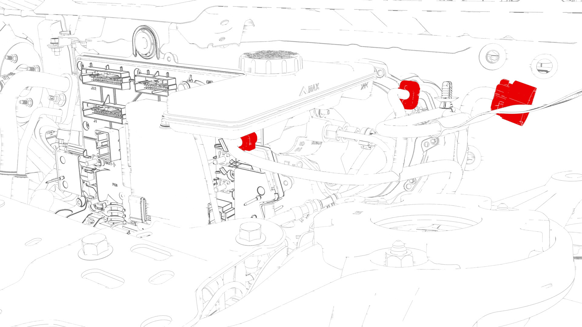
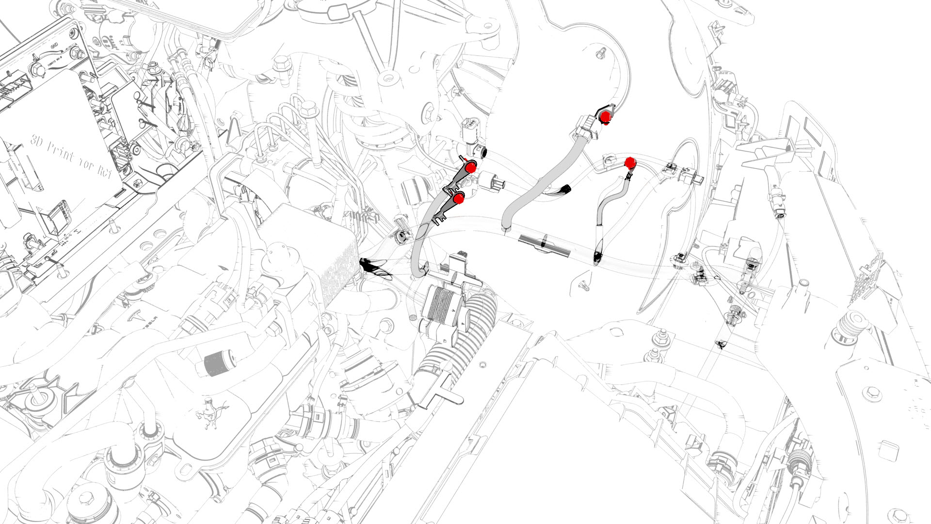
| 19 | Remove the bolt that attaches the thermal harness cover to the front body controller module, and then remove the cover from the module. | |
| 20 | Disconnect the thermal harness from the front body controller module connector. | |
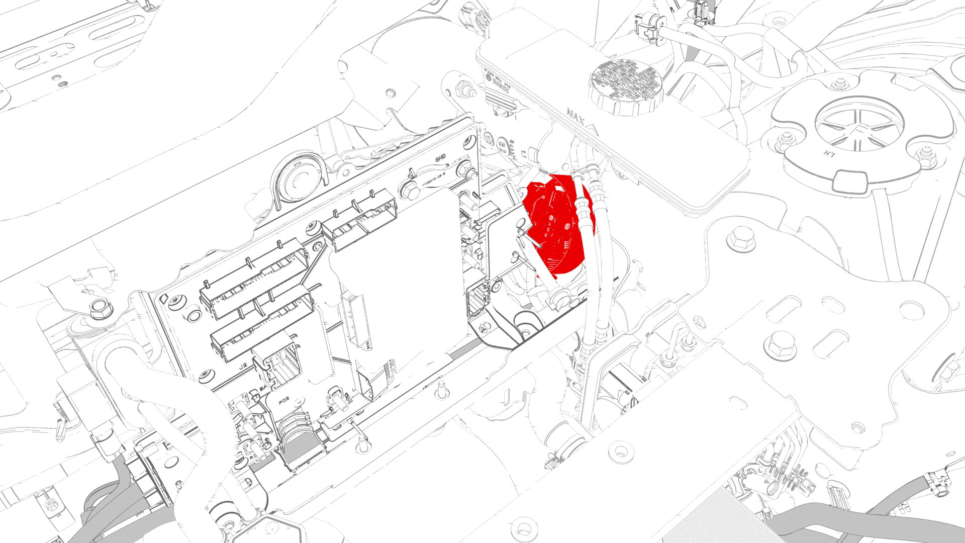
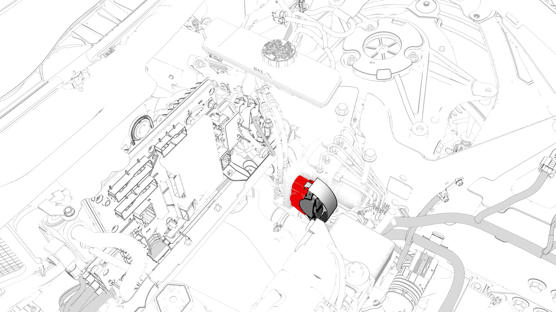
| 21 | Release the clip that attaches the suction/liquid lines to the body near the TXV, and then move the electrical harness aside to gain access to the front body controller module. | |
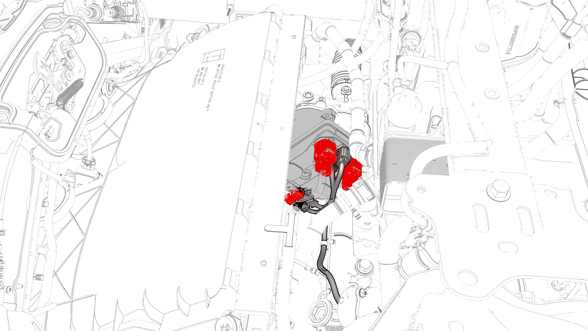
| 22 | Remove the bolts that attach the front body controller module cover to the front body controller module, and then remove the cover. | |
| 23 | Disconnect the main front harness from the front body controller module connectors. | |
| 24 | Remove and discard the nuts (x6) and bolt that attach the power and ground cables to the front body controller module. | |
| 25 | Remove the bolts that attach the front body controller module to the body. | |
| 26 | Release the clips that attach the bottom of the front body controller module to the body, and then remove the lower busbar from the stud. | |
| 27 | Remove the bolt that attaches the ground strap to the upper rear of the front body controller module, and then remove the ground strap from the module. | |
| 28 | Remove the bolt that attaches the ground strap to the lower right side of the front body controller module, and then remove the ground strap from the module. | |
| 29 | Remove the bolt that attaches the ground strap to the lower rear of the front body controller module, and then remove the module from the vehicle. | |
| 30 | Remove the 12V battery bracket. See Bracket - 12V Battery (RWD) (Remove and Replace). | ||
| 31 | Release the clips that attach the HVAC plenum outer duct to the HVAC plenum inner duct, and then remove the outer duct. | |
| 32 | Remove the fasteners that attach the HVAC plenum inner duct to the body, and then remove the inner duct from the vehicle. | |
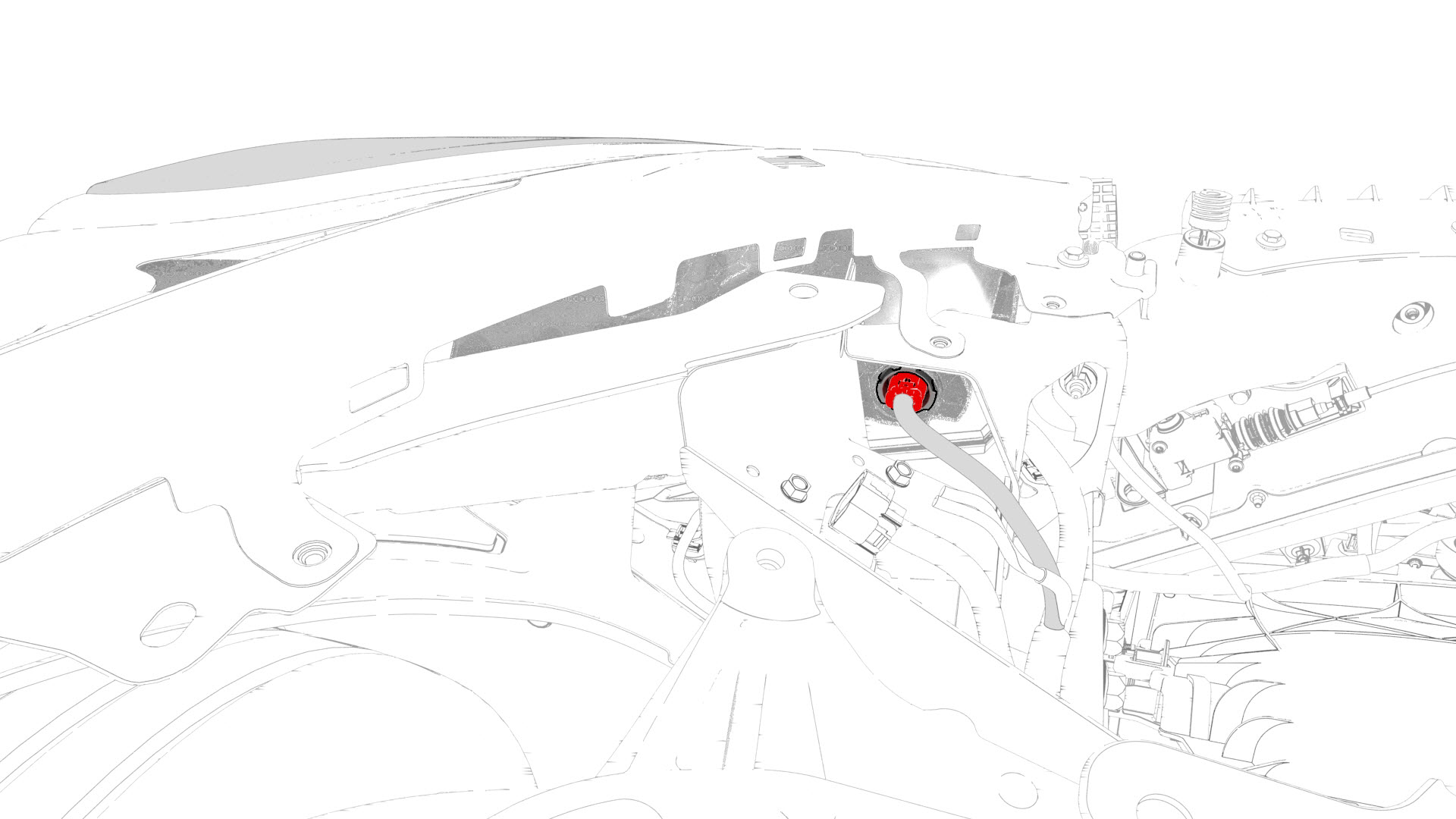
| 33 | Disconnect the electrical harness from the RH body controller module connector. | |
| 34 | Remove and discard the nuts (x2) that attach the power cables of the electrical harness to the RH body controller module, and remove the power cables from the module. | |
| 35 | Remove and discard the nut that attaches the RH body controller module to the A-pillar, and lower the module for access. | |
| 36 | Release the clip that attaches the inline electrical harness connector to the RH body controller module, and then disconnect the electrical connector. | |
| 37 | Release the clips that attach the electrical harness to the car computer. | |
| 38 | Disconnect the electrical harness from the car computer connectors (x7). | |
| 39 | Push the RH side of the electrical harness out through the bulkhead. | ||
| 40 | Disconnect the electrical harness from the LH body controller module connector. | |
| 41 | Remove and discard the nut that attaches the power cable of the electrical harness to the LH body controller module, and remove the power cable from the module. | |
| 42 | Release the clip that attaches the inline electrical harness connector X909 to the LH body controller module, and then disconnect the electrical connector. | |
| 43 | Push the LH side of the electrical harness out through the bulkhead. | ||
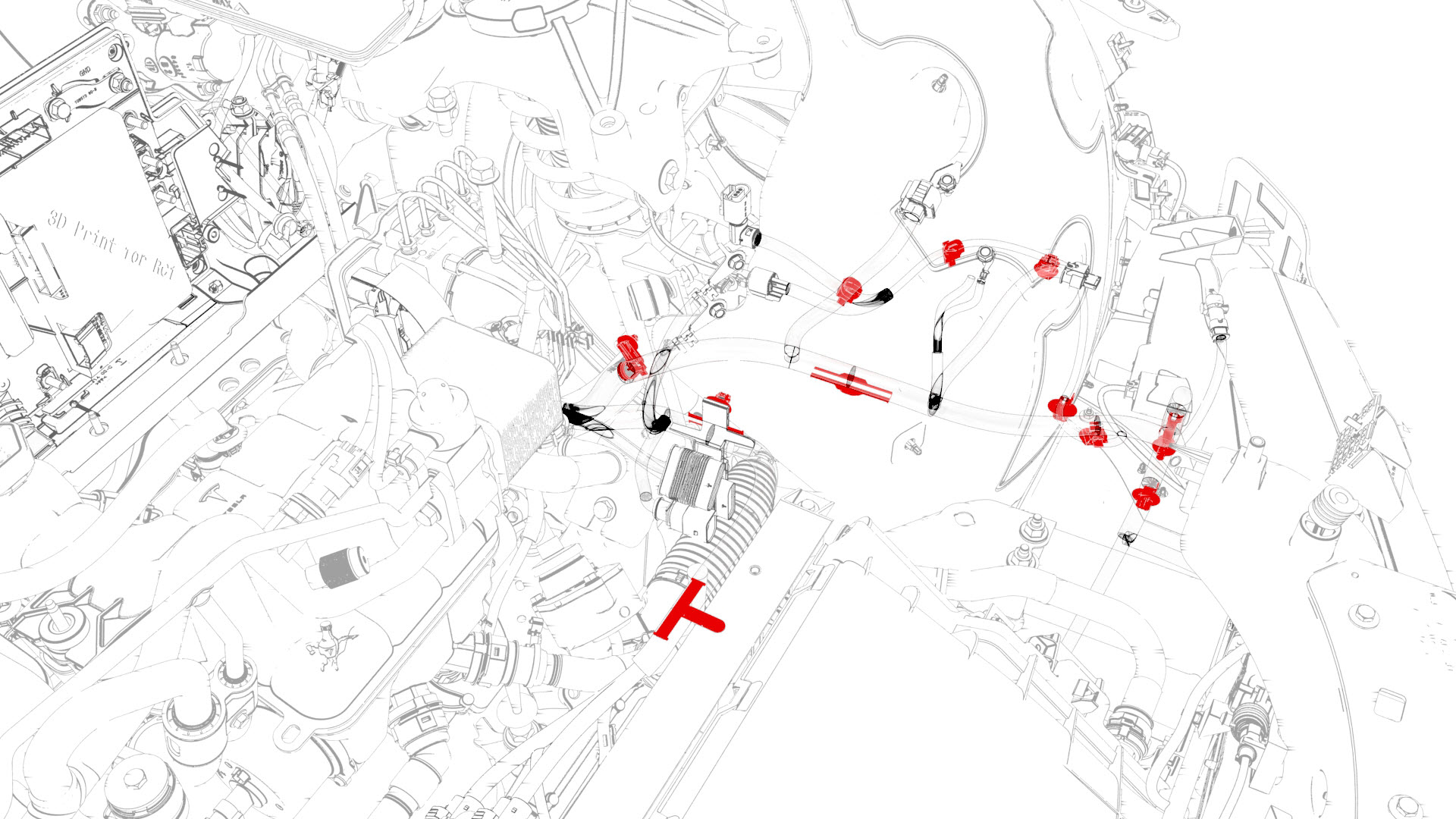
| 44 | Release the clip that attaches the electrical harness to the body in the brake booster area. | |
| 45 | Disconnect the electrical harness from the connectors (x3) in the brake booster area. | |
| 46 | Disconnect the electrical harness from the brake booster connector. | |
| 47 | Disconnect the electrical harness from the ABS unit connector. | |
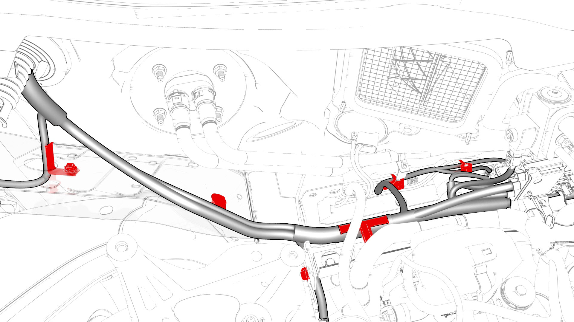
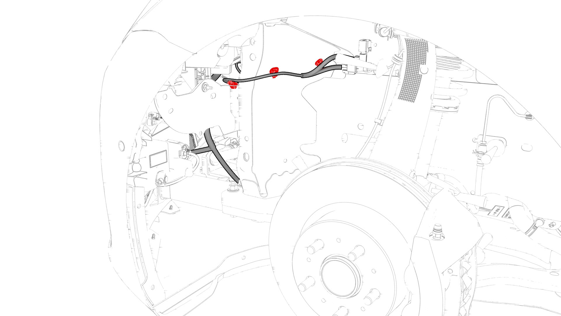
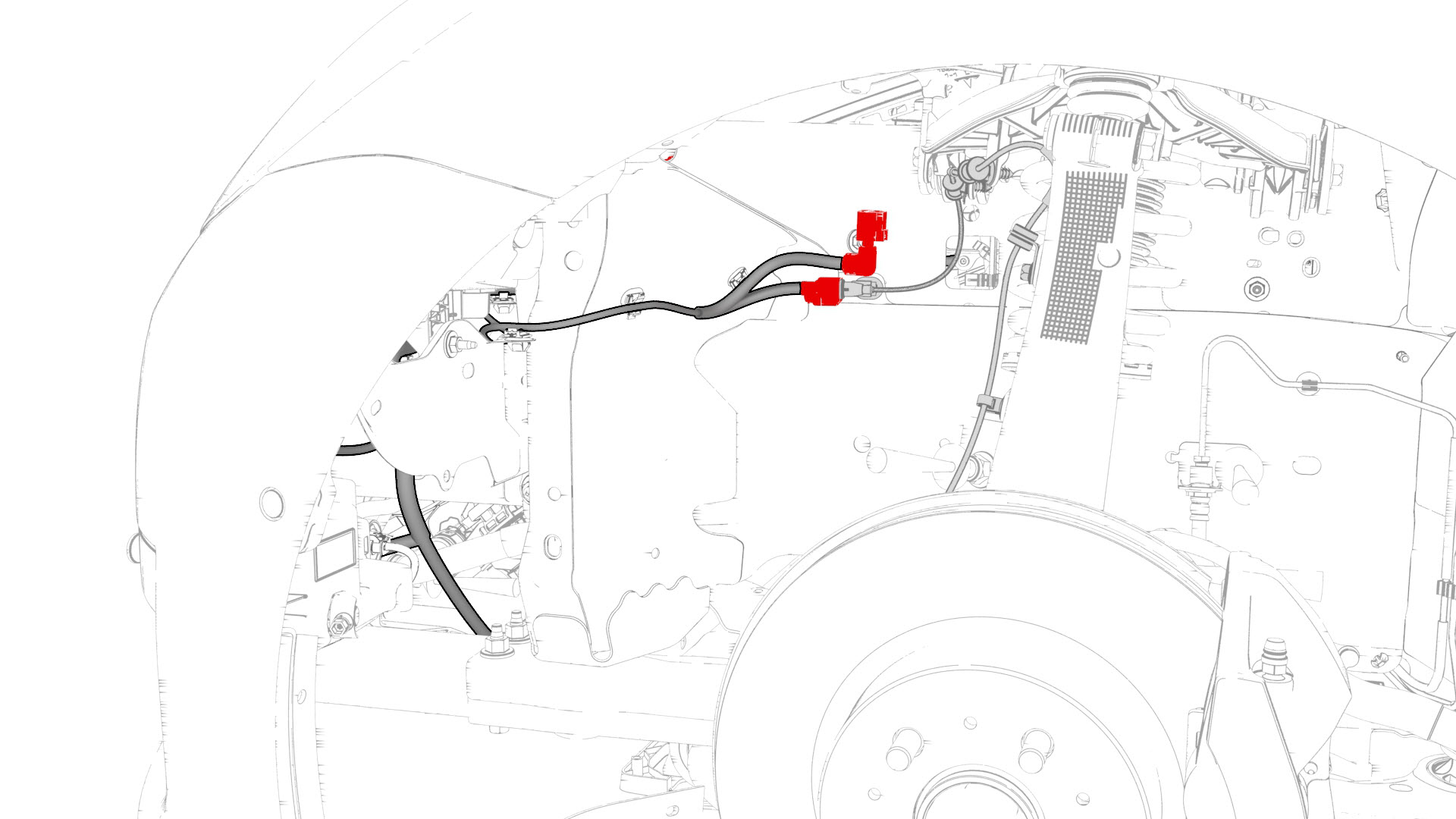
| 48 | Release the clips that attach the electrical harness to the body in the front LH frame rail area. | |
| 49 | Remove and discard the bolts (x4) that attach the electrical harness ground terminals to the body in the front LH frame rail area. | |
| 50 | Disconnect the electrical harness from the steering rack connectors and connectors in the front LH frame rail area. | |
| 51 | Disconnect the electrical harness from the LH headlight connector. | |
| 52 | Release the clips that attach the electrical harness to the body in the HVAC plenum duct area. | |
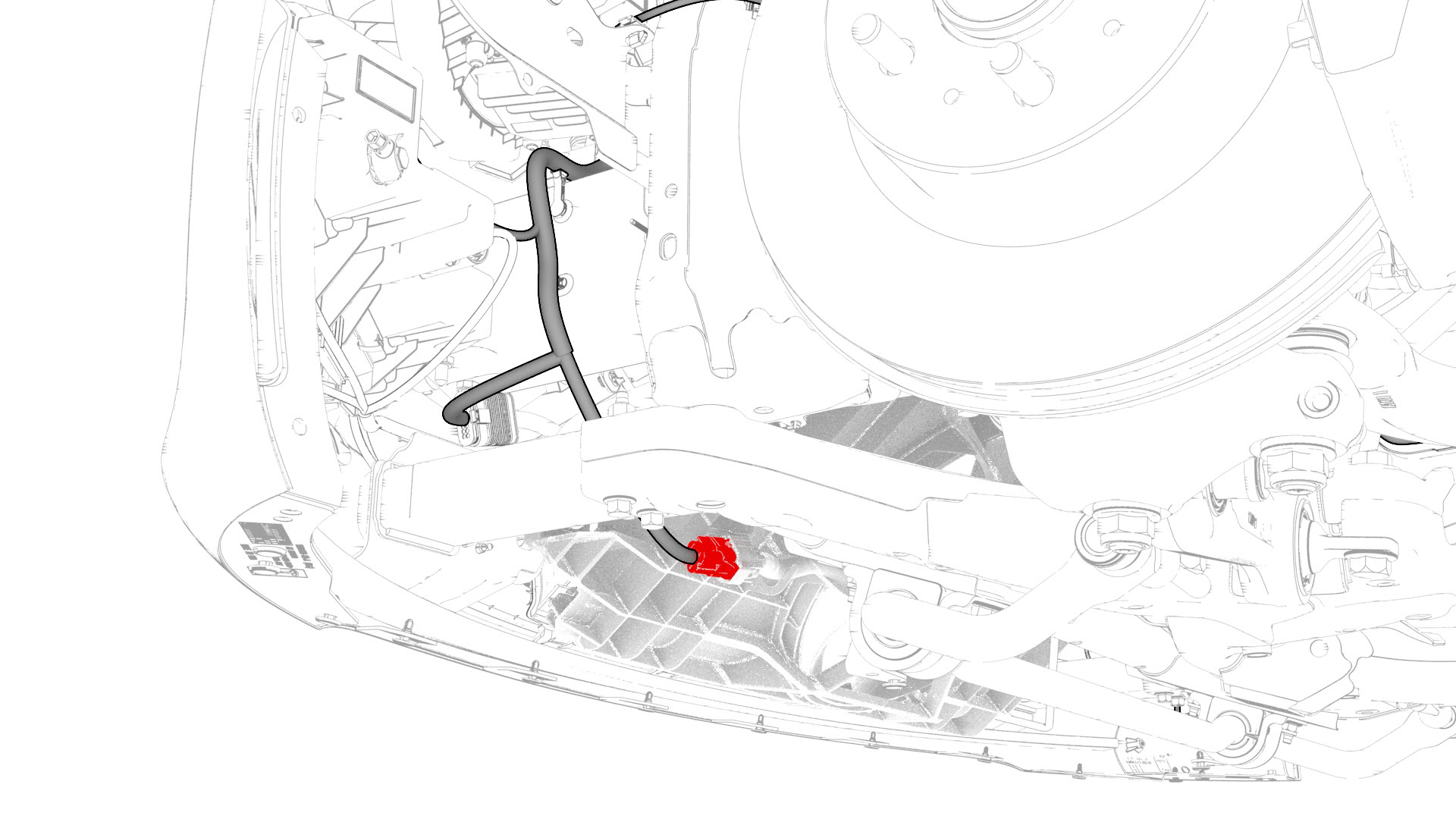
| 53 | Disconnect the electrical harness from the TXV connector. | |
| 54 | Remove the bolt that attaches the electrical harness ground terminal to the body in the TXV area | |
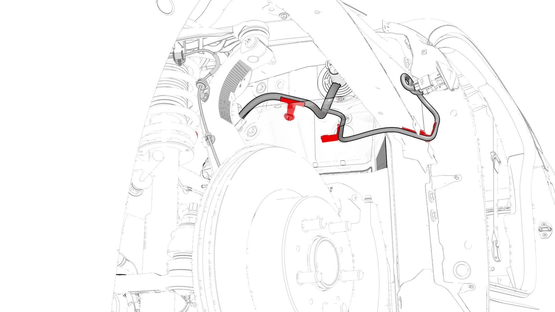
| 55 | Release the clips that attach the electrical harness to the body in the front RH frame rail area. | |
| 56 | Remove and discard the bolt that attaches the electrical harness ground terminal to the body in the front RH frame rail area. | |
| 57 | Release the clips that attach the electrical harness to the body in the RH headlight area. | |
| 58 | Disconnect the electrical harness from the RH headlight connector. | |
| 59 | Partially close all doors. | ||
| 60 | Remove the wheel chocks. | ||
| 61 | With an assistant, move the vehicle to a lift. Caution: The vehicle is safely pushed for only a very short distance and at a very slow speed.
| ||
| 62 | Remove the front LH and front RH wheels. See Wheel (Remove and Install). | ||
| 63 | Remove the front LH and front RH arch liners. See Wheel Arch Liner - Front - LH (Remove and Replace). | ||
| 64 | Disconnect the electrical harness from the connectors in the front RH fascia area. | |
| 65 | Release the clips that attach the electrical harness to the body at the front of the front RH wheel liner area. | |
| 66 | Disconnect the electrical harness from the connector at the front of the front RH wheel liner area. | |
| 67 | Release the clips that attach the electrical harness to the body at the rear of the front RH wheel liner area. | |
| 68 | Disconnect the electrical harness from the front RH side repeater lamp connector. | |
| 69 | Disconnect the electrical harness from the connectors in the front LH fascia area. | |
| 70 | Disconnect the electrical harness from the front end module connector. | |
| 71 | Release the clips that attach the electrical harness to the body in the front LH wheel liner area. | |
| 72 | Disconnect the electrical harness from the connectors at the front of the front LH wheel liner area. | |
| 73 | Release the clips that attach the electrical harness to the body in the front LH wheel area. | |
| 74 | Disconnect the electrical harness from the front LH side repeater lamp connector. | |
| 75 | Lower the vehicle. | ||
| 76 | Release the clips that attach the electrical harness to the body in the front RH frame area. | |
| 77 | Release the clips that attach the electrical harness to the body in the bulkhead area. | |
| 78 | Disconnect the electrical harness from the connectors in the bulkhead area. | |
| 79 | Release the clips that attach the electrical harness to the body in the LH frame rail area. | |
| 80 | Route the LH side of the electrical harness from the wheel liner, through the underhood storage unit area, and to the front body controller module area. | ||
| 81 | Route the RH side of the electrical harness from the wheel liner, through the underhood storage unit area, and to the front body controller module area. | ||
| 82 | Remove the electrical harness from the vehicle. |
Install
-
Fasten the clips that attach the electrical harness to the body in the LH frame rail area.
-
Connect the electrical harness to the connectors in the bulkhead area.
-
Fasten the clips that attach the electrical harness to the body in the bulkhead area.
-
Fasten the clips that attach the electrical harness to the body in the front RH frame area.
-
Connect the electrical harness to the front LH side repeater lamp connector.
-
Fasten the clips that attach the electrical harness to the body in the front LH wheel area.
-
Connect the electrical harness to the connectors at the front of the front LH wheel liner area.
-
Fasten the clips that attach the electrical harness to the body at the front LH wheel liner area.
-
Connect the electrical harness to the front end module connector.
-
Connect the electrical harness to the connectors in the front LH fascia area.
-
Connect the electrical harness to the front RH side repeater lamp connector.
-
Fasten the clips that attach the electrical harness to the body at the rear of the front RH wheel liner area.
-
Connect the electrical harness to the connector at the front of the front RH wheel liner area.
-
Fasten the clips that attach the electrical harness to the body at the front of the front RH wheel liner area.
-
Connect the electrical harness to the connectors in the front RH fascia area.
-
With an assistant, move the vehicle from the lift.
Caution:The vehicle is safely pushed for only a very short distance and at a very slow speed.
-
Connect the electrical harness to the RH headlight connector.
-
Fasten the clips that attach the electrical harness to the body in the RH headlight area.
-
Install a new bolt to attach the electrical harness ground terminal to the body in the front RH frame rail area.
 Torque 8 Nm
 -
Fasten the clips that attach the electrical harness to the body in the front RH frame rail area.
-
Install the bolt that attaches the electrical harness ground terminal to the body in the TXV area
 Torque 9 Nm
 -
Connect the electrical harness to the TXV connector.
-
Fasten the clips that attach the electrical harness to the body in the HVAC plenum duct area.
-
Connect the electrical harness to the LH headlight connector.
-
Connect the electrical harness to the steering rack connectors and the connectors in the front LH frame rail area.
-
Install new bolts (x4) to attach the electrical harness ground terminals to the body in the front LH frame rail area.Torque 8 Nm
-
Fasten the clips that attach the electrical harness to the body in the front LH frame rail area.
-
Connect the electrical harness to the ABS unit connector.
-
Connect the electrical harness to the brake booster connector.
-
Connect the electrical harness to the connectors (x3) in the brake booster area.
-
Fasten the clip that attaches the electrical harness to the body in the brake booster area.
-
Connect the electrical harness to the LH body controller module connector.
-
Connect the inline electrical harness connector X909, and then attach it to the LH body controller module.
-
Install the power cable of the electrical harness to the LH body controller module, and then install a new nut to attach the power cable to the module.
 Torque 8.5 Nm
 -
Connect the electrical harness to the car computer connectors (x7).
-
Fasten the clips that attach the electrical harness to the car computer.
-
Connect the inline electrical harness connector, and then attach it to the RH body controller module.
-
Raise the RH body controller module into position, and install a new nut to attach the module to the A-pillar.
 Torque 6 Nm
 -
Install the power cables of the electrical harness to the RH body controller module, and then install the new nuts (x2) to attach the power cables to the module.Torque 8.5 Nm
-
Connect the electrical harness to the RH body controller module connector.
-
Install the HVAC plenum inner duct to the body, and then install the fasteners that attach the inner duct to the body.
-
Install the HVAC plenum outer duct onto the HVAC plenum inner duct, and then fasten the clips that attach the outer duct to the inner duct.
-
Install the front body controller module to the body, and then install the bolt that attaches the ground strap to the lower rear of the module.
 Torque 9 Nm
 -
Install the ground strap to the lower right side of the front body controller module, and then install the bolt that attaches the ground strap to the moduleTorque 9 Nm
-
Install the ground strap to the upper rear of the front body controller module, and then install the bolt that attaches the ground strap to the module.Torque 9 Nm
-
Install the lower busbar onto the stud, and then fasten the clips that attach the bottom of the front body controller module to the body.
-
Install the bolts that attach the front body controller module to the body.
 Torque 10 Nm
 Torque 10 Nm
 -
Install new nuts (x6) and new bolt to attach the power and ground cables to the front body controller module.
 Torque 8.5 Nm
 Torque 8.5 NmNote: Make sure that the terminal lugs fit in their channels neatly.
 -
Connect the main front harness to the front body controller module connectors.
-
Visually inspect that the power and the ground cables exit the front body controller module neatly in their respective channels, and parallel to each other.
Caution:Make sure that no cables or wires will be pinched when the front body controller module cover is installed.
-
Install the front body controller module cover to the front body controller module, and then install the bolts that attach the cover to the module.
 Torque 6 Nm
 -
Fasten the clip that attaches the suction/liquid lines to the body near the TXV.
-
Connect the thermal harness to the front body controller module connector.
-
Install the thermal harness cover to the front body controller module, and then install the bolt that attaches the cover to the module.
 Torque 6 Nm
| 1 | Install the electrical harness into the vehicle. | ||
| 2 | Route the RH side of the electrical harness from the front body controller module area, through the underhood storage unit area, and to the RH wheel liner. | ||
| 3 | Route the LH side of the electrical harness from the front body controller module area, through the underhood storage unit area, and to the LH wheel liner. | ||
| 4 | Fasten the clips that attach the electrical harness to the body in the LH frame rail area. | |
| 5 | Connect the electrical harness to the connectors in the bulkhead area. | |
| 6 | Fasten the clips that attach the electrical harness to the body in the bulkhead area. | |
| 7 | Fasten the clips that attach the electrical harness to the body in the front RH frame area. | |
| 8 | Raise the vehicle. | ||
| 9 | Connect the electrical harness to the front LH side repeater lamp connector. | |
| 10 | Fasten the clips that attach the electrical harness to the body in the front LH wheel area. | |
| 11 | Connect the electrical harness to the connectors at the front of the front LH wheel liner area. | |
| 12 | Fasten the clips that attach the electrical harness to the body at the front LH wheel liner area. | |
| 13 | Connect the electrical harness to the front end module connector. | |
| 14 | Connect the electrical harness to the connectors in the front LH fascia area. | |
| 15 | Connect the electrical harness to the front RH side repeater lamp connector. | |
| 16 | Fasten the clips that attach the electrical harness to the body at the rear of the front RH wheel liner area. | |
| 17 | Connect the electrical harness to the connector at the front of the front RH wheel liner area. | |
| 18 | Fasten the clips that attach the electrical harness to the body at the front of the front RH wheel liner area. | |
| 19 | Connect the electrical harness to the connectors in the front RH fascia area. | |
| 20 | Install the front LH and front RH arch liners. See Wheel Arch Liner - Front - LH (Remove and Replace). | ||
| 21 | Install the front LH and front RH wheels. See Wheel (Remove and Install). | ||
| 22 | With an assistant, move the vehicle from the lift. Caution: The vehicle is safely pushed for only a very short distance and at a very slow speed.
| ||
| 23 | Place wheel chocks on both rear wheels. | ||
| 24 | Open the front LH and front RH doors. | ||
| 25 | Connect the electrical harness to the RH headlight connector. | |
| 26 | Fasten the clips that attach the electrical harness to the body in the RH headlight area. | |
| 27 | Install a new bolt to attach the electrical harness ground terminal to the body in the front RH frame rail area. Torque 8 Nm | |
| 28 | Fasten the clips that attach the electrical harness to the body in the front RH frame rail area. | |
| 29 | Install the bolt that attaches the electrical harness ground terminal to the body in the TXV area Torque 9 Nm | |
| 30 | Connect the electrical harness to the TXV connector. | |
| 31 | Fasten the clips that attach the electrical harness to the body in the HVAC plenum duct area. | |
| 32 | Connect the electrical harness to the LH headlight connector. | |
| 33 | Connect the electrical harness to the steering rack connectors and the connectors in the front LH frame rail area. | |
| 34 | Install new bolts (x4) to attach the electrical harness ground terminals to the body in the front LH frame rail area. Torque 8 Nm | |
| 35 | Fasten the clips that attach the electrical harness to the body in the front LH frame rail area. | |
| 36 | Connect the electrical harness to the ABS unit connector. | |
| 37 | Connect the electrical harness to the brake booster connector. | |
| 38 | Connect the electrical harness to the connectors (x3) in the brake booster area. | |
| 39 | Fasten the clip that attaches the electrical harness to the body in the brake booster area. | |
| 40 | Move the LH side of the electrical harness in through the bulkhead. | ||
| 41 | Connect the electrical harness to the LH body controller module connector. | |
| 42 | Connect the inline electrical harness connector X909, and then attach it to the LH body controller module. | |
| 43 | Install the power cable of the electrical harness to the LH body controller module, and then install a new nut to attach the power cable to the module. Torque 8.5 Nm | |
| 44 | Move the RH side of the electrical harness in through the bulkhead. | ||
| 45 | Connect the electrical harness to the car computer connectors (x7). | |
| 46 | Fasten the clips that attach the electrical harness to the car computer. | |
| 47 | Connect the inline electrical harness connector, and then attach it to the RH body controller module. | |
| 48 | Raise the RH body controller module into position, and install a new nut to attach the module to the A-pillar. Torque 6 Nm | |
| 49 | Install the power cables of the electrical harness to the RH body controller module, and then install the new nuts (x2) to attach the power cables to the module. Torque 8.5 Nm | |
| 50 | Connect the electrical harness to the RH body controller module connector. | |
| 51 | Install the HVAC plenum inner duct to the body, and then install the fasteners that attach the inner duct to the body. | |
| 52 | Install the HVAC plenum outer duct onto the HVAC plenum inner duct, and then fasten the clips that attach the outer duct to the inner duct. | |
| 53 | Install the 12V battery bracket. See Bracket - 12V Battery (RWD) (Remove and Replace). | ||
| 54 | Install the front body controller module to the body, and then install the bolt that attaches the ground strap to the lower rear of the module. Torque 9 Nm | |
| 55 | Install the ground strap to the lower right side of the front body controller module, and then install the bolt that attaches the ground strap to the module Torque 9 Nm | |
| 56 | Install the ground strap to the upper rear of the front body controller module, and then install the bolt that attaches the ground strap to the module. Torque 9 Nm | |
| 57 | Install the lower busbar onto the stud, and then fasten the clips that attach the bottom of the front body controller module to the body. | |
| 58 | Install the bolts that attach the front body controller module to the body. Torque 10 Nm Torque 10 Nm | |
| 59 | Install new nuts (x6) and new bolt to attach the power and ground cables to the front body controller module. Torque 8.5 Nm Torque 8.5 Nm Note: Make sure that the terminal lugs fit in their channels neatly.
| |
| 60 | Connect the main front harness to the front body controller module connectors. | |
| 61 | Visually inspect that the power and the ground cables exit the front body controller module neatly in their respective channels, and parallel to each other. Caution: Make sure that no cables or wires will be pinched when the front body controller module cover is installed.
| |
| 62 | Install the front body controller module cover to the front body controller module, and then install the bolts that attach the cover to the module. Torque 6 Nm | |
| 63 | Fasten the clip that attaches the suction/liquid lines to the body near the TXV. | |
| 64 | Connect the thermal harness to the front body controller module connector. | |
| 65 | Install the thermal harness cover to the front body controller module, and then install the bolt that attaches the cover to the module. Torque 6 Nm | |
| 66 | Install the wiper motor assembly. See Wiper Motor (Remove and Replace). | ||
| 67 | Install the nut that attaches the 12V battery rear hook tie down. | ||
| 68 | Install the 12V auxiliary battery. SeeBattery - 12V (Remove and Replace). | ||
| 69 | Install the underhood storage unit. See Underhood Storage Unit (Remove and Replace). | ||
| 70 | Install the RH air wave duct. See Duct - Air Wave - RH (Remove and Replace). | ||
| 71 | Install the RH footwell duct. See Duct - Footwell - RH (Remove and Replace). | ||
| 72 | Install the glove box. See Glove Box (LHD) (Remove and Replace). | ||
| 73 | Install the main instrument panel decor. See Decor Trim - Instrument Panel - Main (Remove and Replace). | ||
| 74 | Install the front passenger knee airbag. See Airbag - Knee - Front Passenger (Remove and Replace) | ||
| 75 | Install the RH lower A-pillar trim. See Trim - A-Pillar - Lower - LH (Remove and Replace). | ||
| 76 | Fasten the clips that attach the footrest. | ||
| 77 | Install the driver knee airbag. See Airbag - Knee - Driver (Remove and Install). | ||
| 78 | Install the LH lower A-pillar trim. See Trim - A-Pillar - Lower - LH (Remove and Replace). | ||
| 79 | Connect 12V power. See 12V Power (Disconnect and Connect). | ||
| 80 | Remove the wheel chocks. | ||
| 81 | Close the hood. | ||
| 82 | Close the front LH and front RH doors. |