Harness - Penthouse - HV Battery (Remove and Replace)
Correction code 1630500216305002
- 1057602-00-ARatchet, 1/4" Sq Dr, HV Insulated
- 1057603-00-AExt Bar, Wobble, 1/4" Dr, HV Insulated
- 1057606-00-ASkt, 1/4" Sq Dr, 13mm, HV Insulated
- 1057607-00-AMagnet, Flexible, HV Insulated, 18"
- 1111868-00-B Connector Removal, Coolant, PCS, M3
- 1135762-00-AKit, Svc Plug, Cooling Hose, Model 3
- 1059330-00-BSkt, 1/4in Dr, 5-Lobe Torx Plus External
- 1475996-00-A UFO Connector Removal Tool
- 1076927-00-A Resistance meter, microohm, Hioki RM 3548
SPECIAL TOOLS
Ratchet, 1/4" Sq Dr, HV Insulated (1057602-00-A) |
Ext Bar, Wobble, 1/4" Dr, HV Insulated (1057603-00-A) |
Skt, 1/4" Sq Dr, 13mm, HV Insulated (1057606-00-A) |
Magnet, Flexible, HV Insulated, 18" (1057607-00-A) |
Connector Removal, Coolant, PCS, M3 (1111868-00-B) |
Kit, Svc Plug, Cooling Hose, Model 3 (1135762-00-A) |
Skt, 1/4in Dr, 5-Lobe Torx Plus External (1059330-00-B) |
UFO Connector Removal Tool (1475996-00-A) |
Resistance meter, microohm, Hioki RM 3548 (1076927-00-A) |
 Warning: Remove all jewelry (watches, bracelets, rings, necklaces, earrings, ID tags, piercings, etc.) from your person, and all objects (keys, coins, pens, pencils, tools, fasteners, etc.) from your pockets before performing any procedure that exposes you to high voltage.Warning: If corrective eyewear is necessary to safely perform any procedure, make sure that the eyewear is securely restrained to the head and cannot fall off.Warning:
Only technicians who have been trained in High Voltage Awareness are permitted to perform this procedure. Proper personal protective equipment (PPE) and insulating HV gloves with a minimum rating of class 0 (1000V) must be worn at all times a high voltage cable, busbar, or fitting is handled. Refer to Tech Note TN-15-92-003, "High Voltage Awareness Care Points" for additional safety information.
Remove
-
Remove the penthouse cover. See Cover - Penthouse (Remove and Replace).
Warning: HV insulating gloves and leather glove protectors must be worn throughout the remainder of this procedure. Do not remove gloves or protectors until otherwise noted.
-
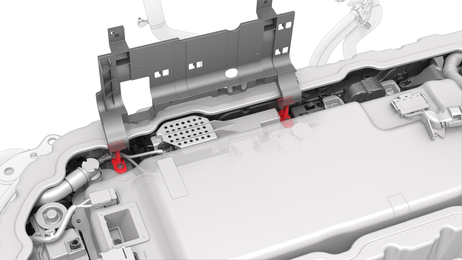
Release the clips (x5) that attach the HV battery penthouse harness to the hinge tray.
Note: Pull and unhook to release the flat rectangular clips.
-
Raise the hinge tray vertically, pull up on the tray at each hinge, and then remove the tray from the vehicle.
-
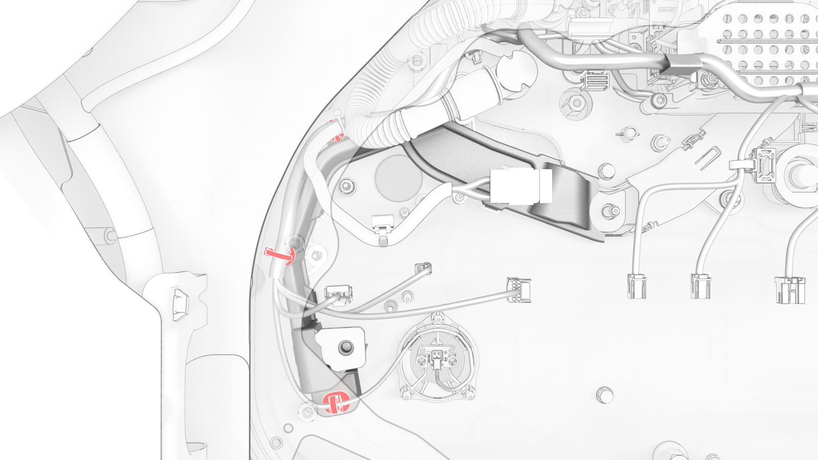
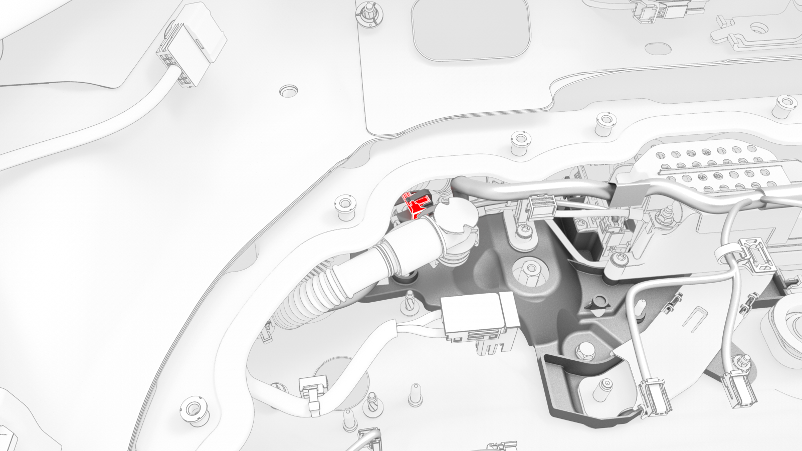
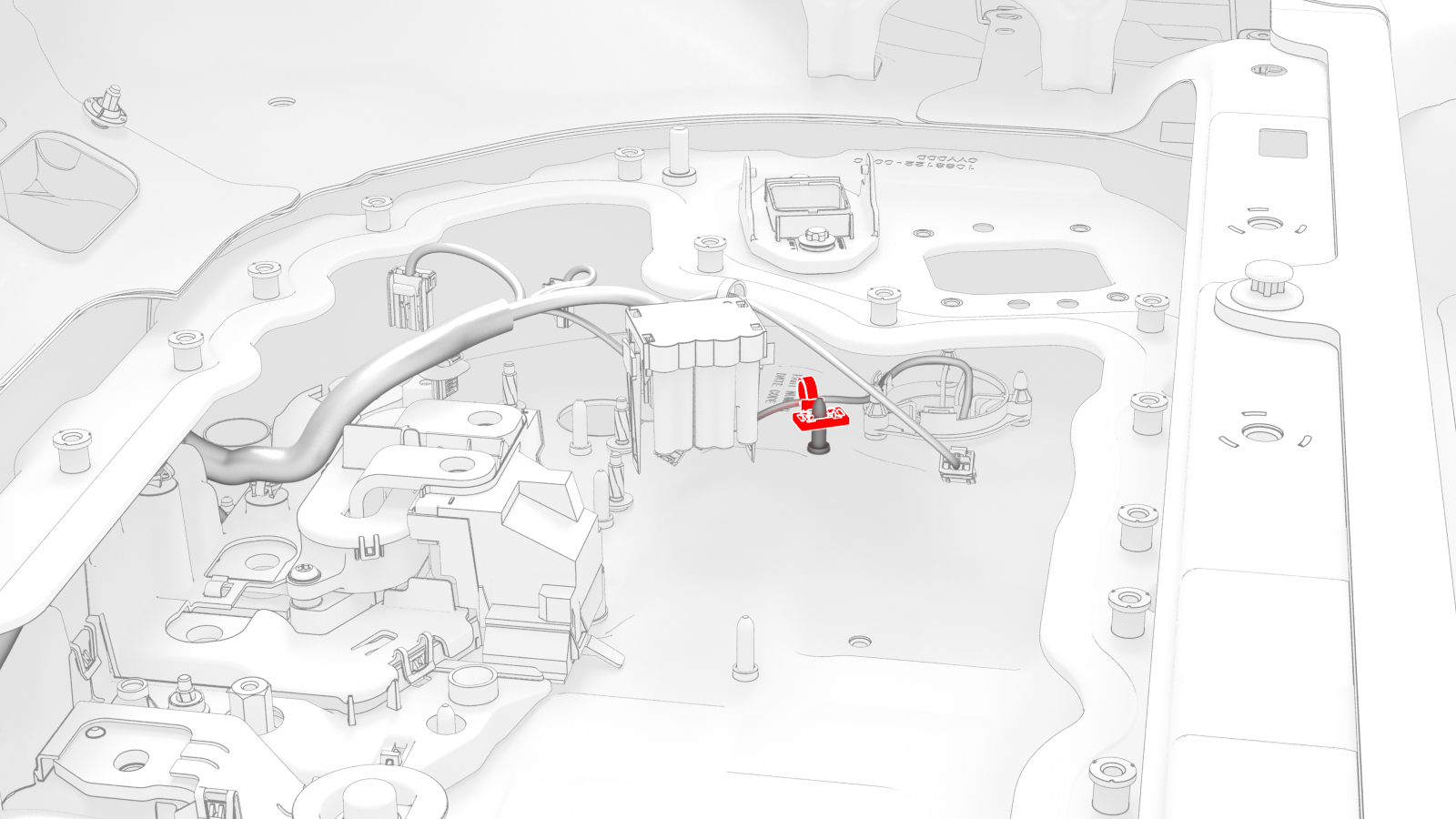
Remove the clip that confines the LH Hall-effect sensor to the LH flood port cover above the LH flood port.
-
Release the tab that holds the LH Hall-effect sensor to the LH flood port cover, and then separate the sensor from under the tab.
-
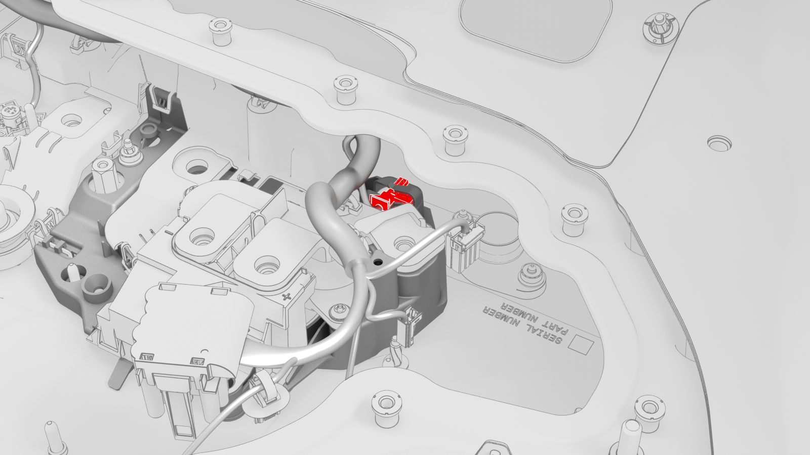
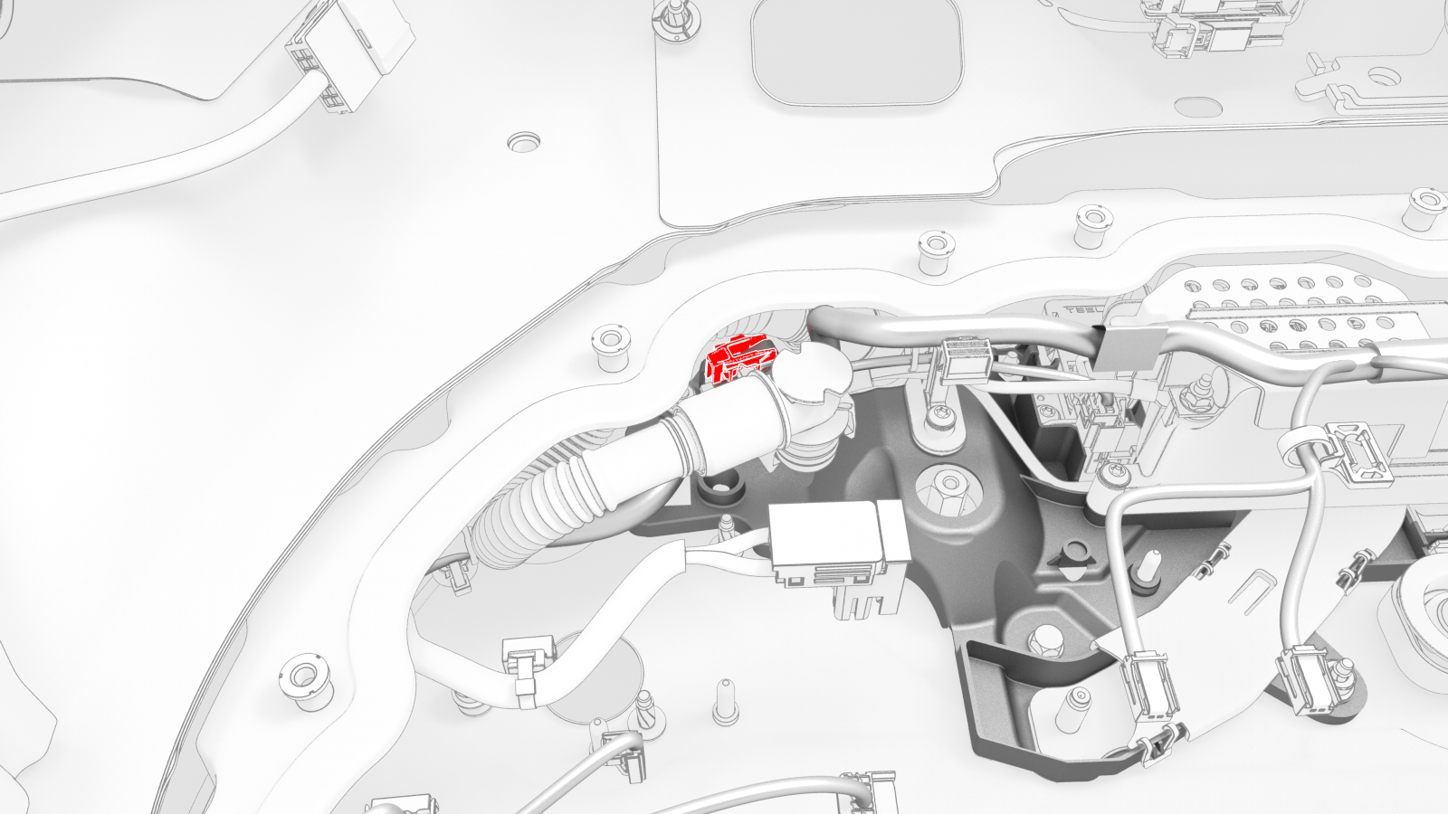
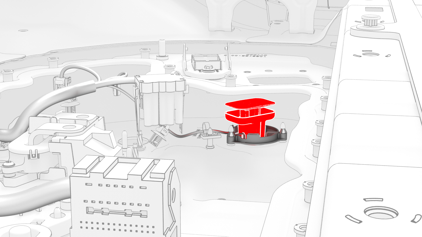
Remove the insulator cap from the nut that joins the positive DC link to the positive busbar.
-
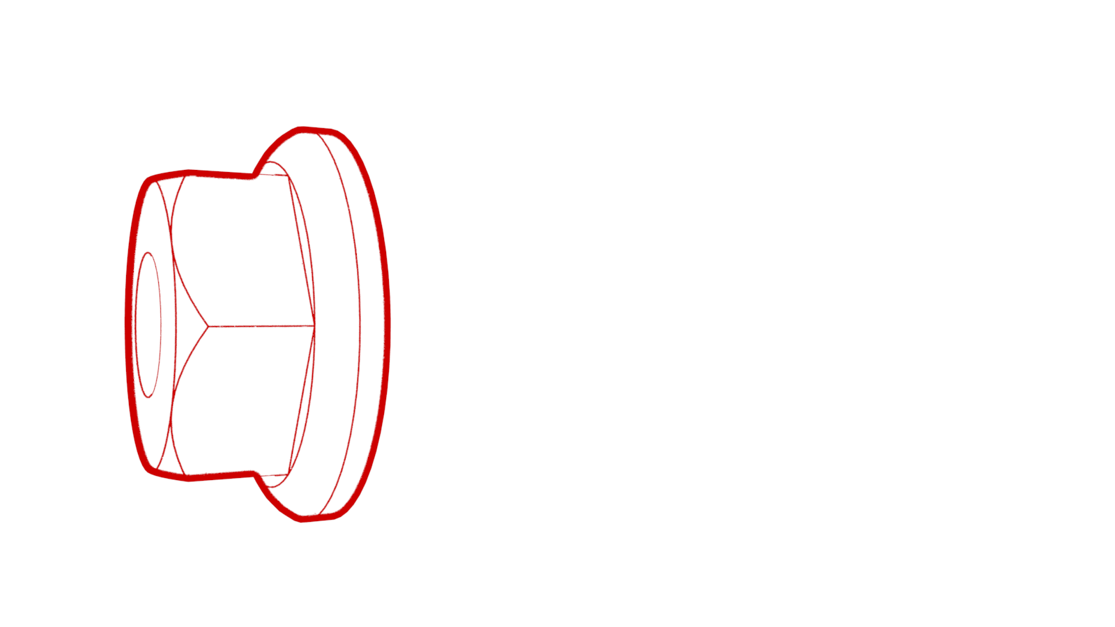
Remove and discard the nut that joins the positive DC link to the positive busbar.
-
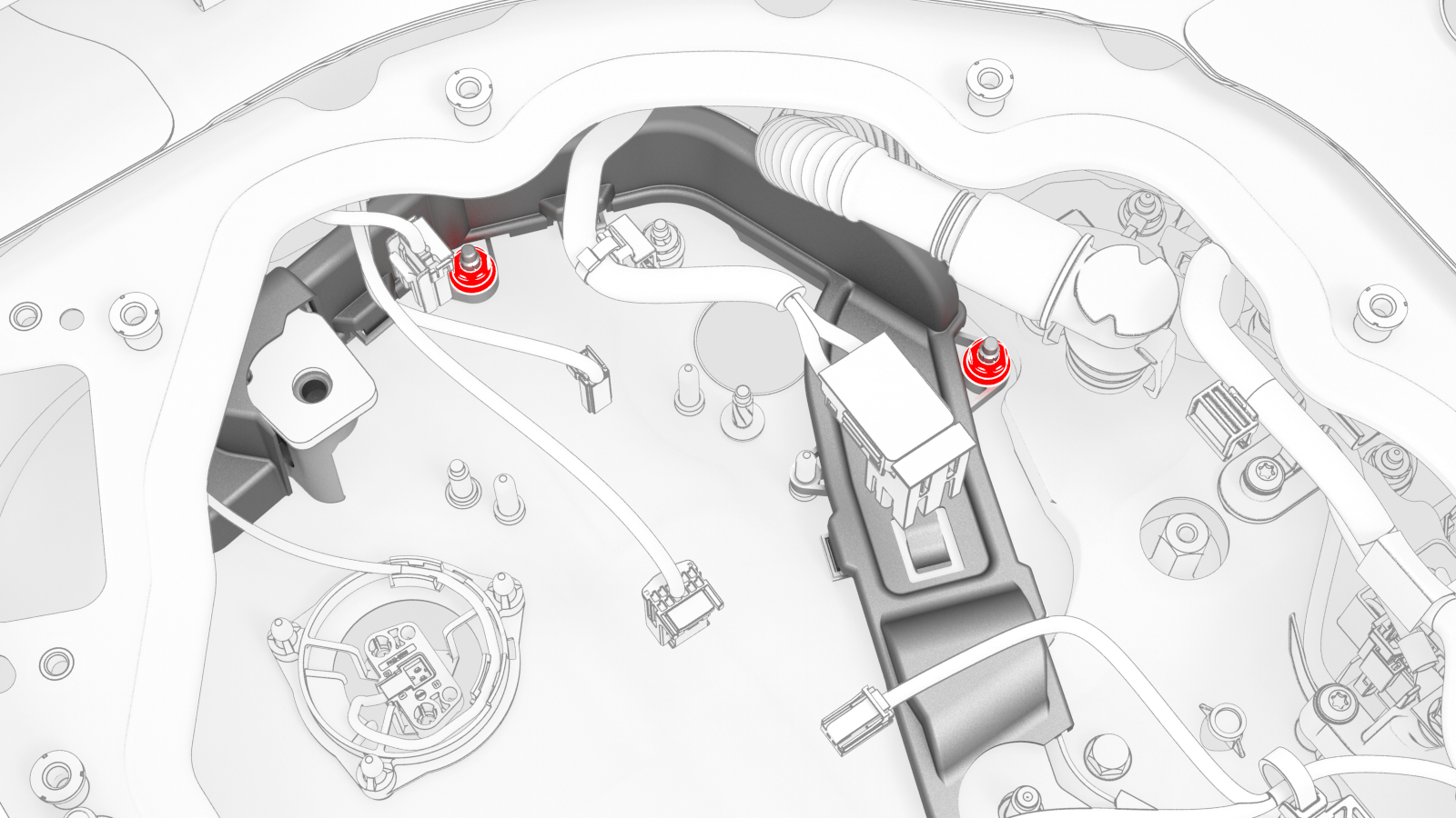
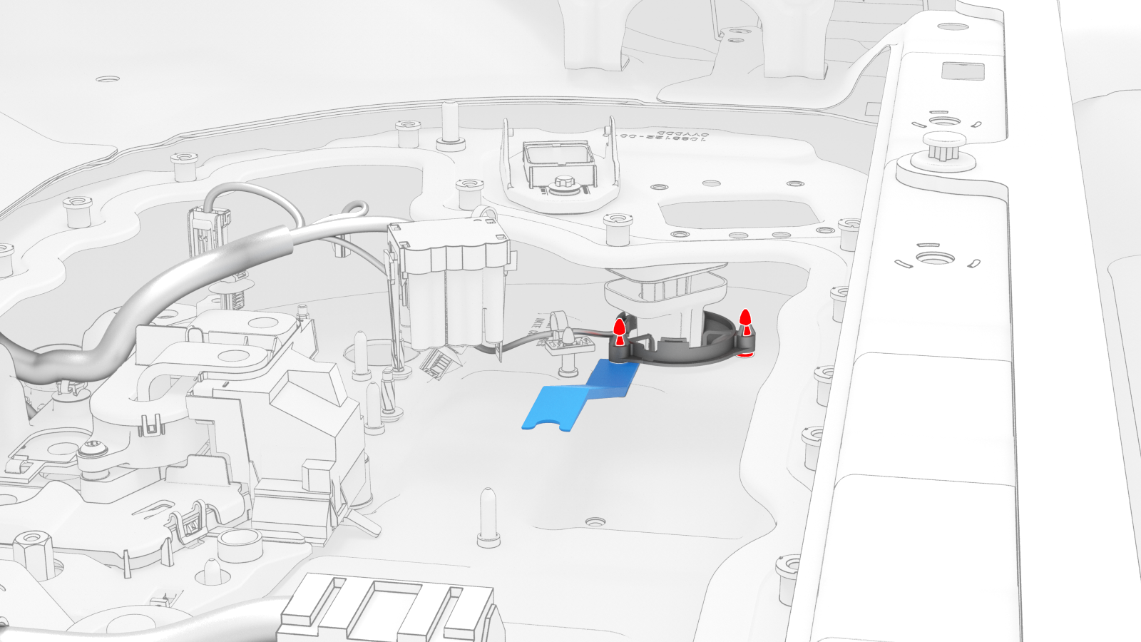
Remove the nuts (x2) that attach the positive DC link to the penthouse floor, lift the link off of the studs and posts, and then move the link inboard to access the HV battery penthouse harness clips.
-
Release the clips that attach the HV battery penthouse harness to the positive DC link insulator, and remove the DC link from the penthouse.
Note: The rear most clip is behind the positive DC link insulator.
-
Use the UFO connector removal tool to disconnect the RH passthrough connector from the HV battery module 4 BMS connector.
 Caution:Do not try to remove the RH passthrough in this step, as it will be damaged. Only disconnect the connector.
 Tip: Access the penthouse from the RH rear door area for this step.
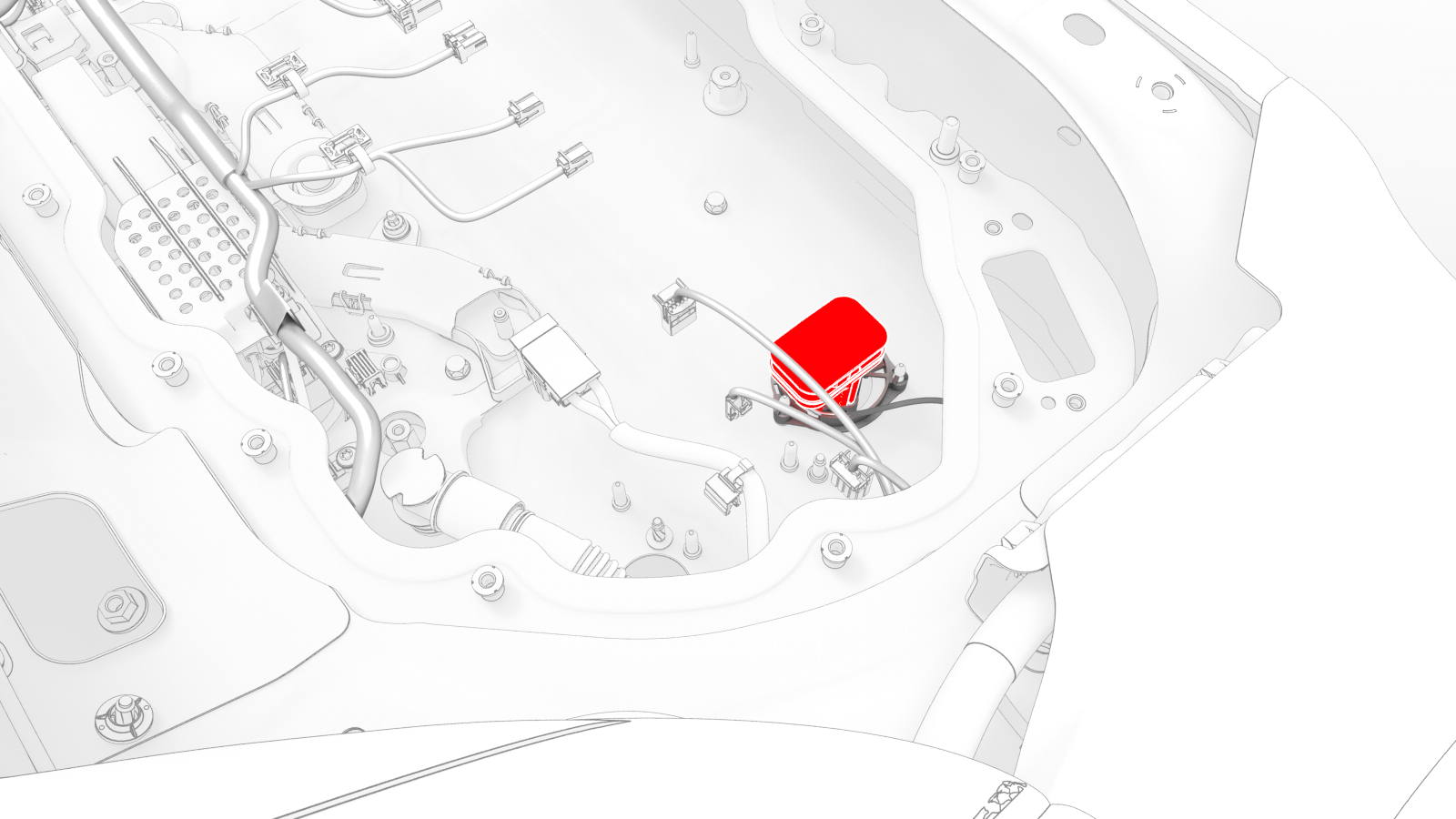 View From RH Rear Door
 -
Use a pry tool to release the RH passthrough clips (x3) that attach the RH passthrough to the posts of the penthouse floor, and then separate the passthrough from the penthouse floor.
-
Remove the clip that confines the RH Hall-effect sensor to the RH flood port cover above the RH flood port.
-
Release the tab that holds the RH Hall-effect sensor to the RH flood port cover, and then separate the sensor from under the tab.
-
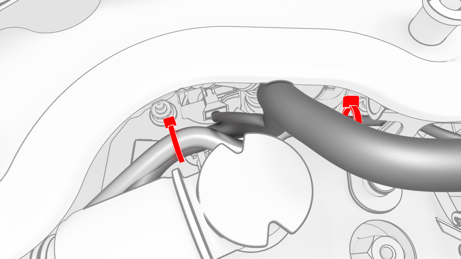
Remove the cable ties that attach the HV battery penthouse harness to the power conversion system DC bus HV harness on either side of the RH Hall-effect sensor.
-
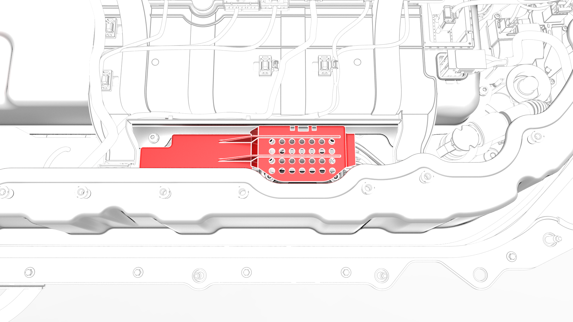
Release the clips that attach the fuse access insulator to the RH penthouse bus cover, and remove the insulator.
-
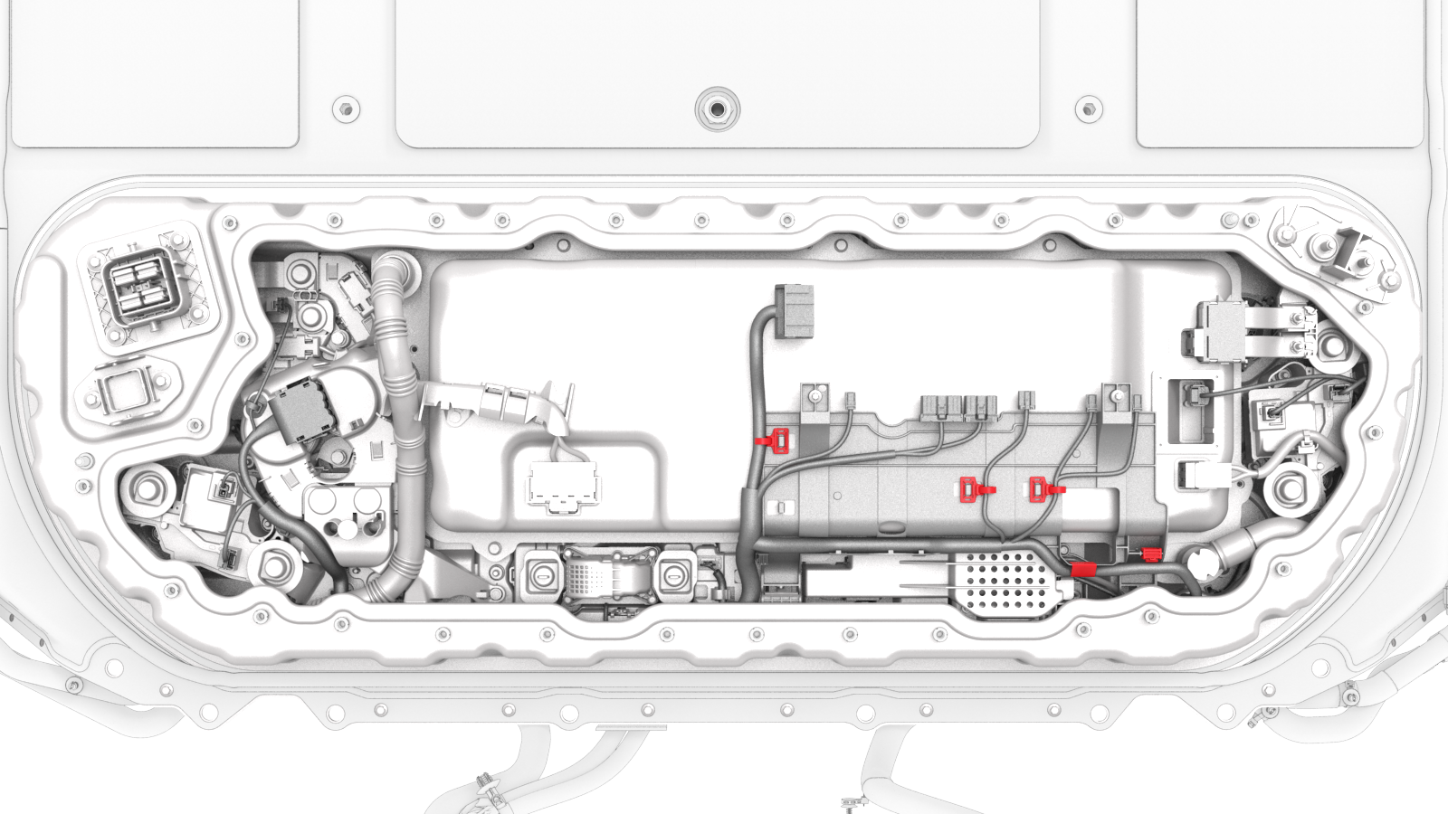
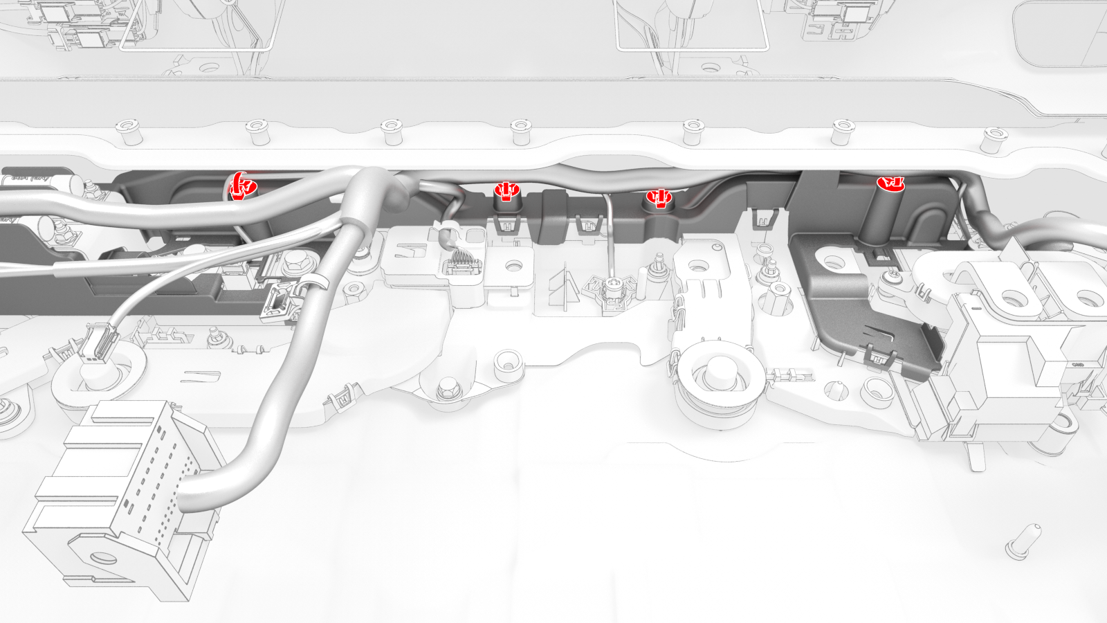
Release the clips (x4) that attach the HV battery penthouse harness along the busbar insulator.
-
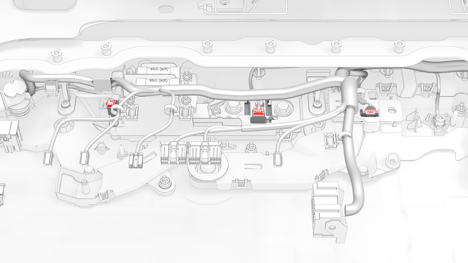
Release the HV battery penthouse harness from under the respective tabs, and disconnect the harness from the A/C compressor and PTC heater high voltage interlock loop connector , the rear drive unit high voltage interlock loop connector, and the shunt connector.
-
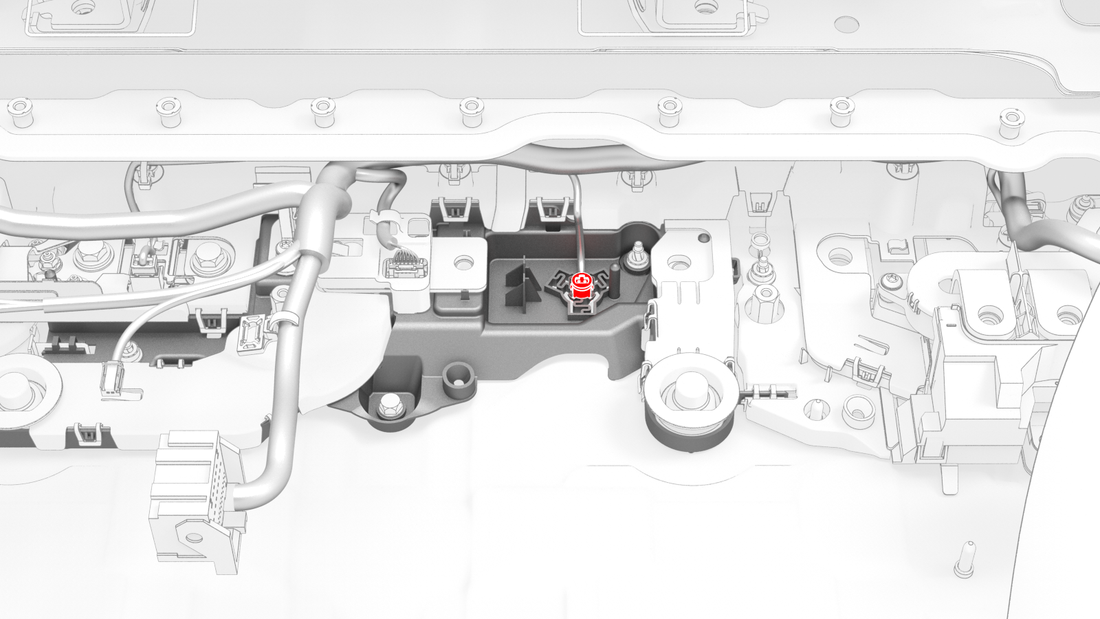
Release the clips that attach the pyrotechnic battery disconnect connector to the penthouse floor, and separate the connector from the floor.
-
If the vehicle is configured with dual motors, release the HV battery penthouse harness from under the tab, and disconnect the harness from the front drive unit high voltage interlock loop connector.
-
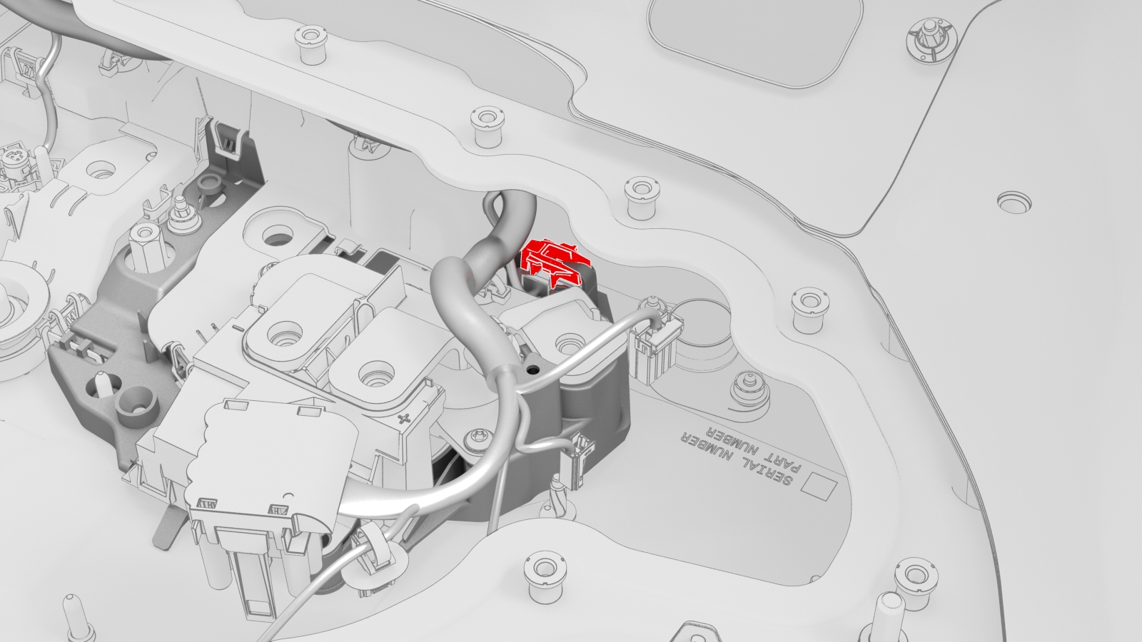
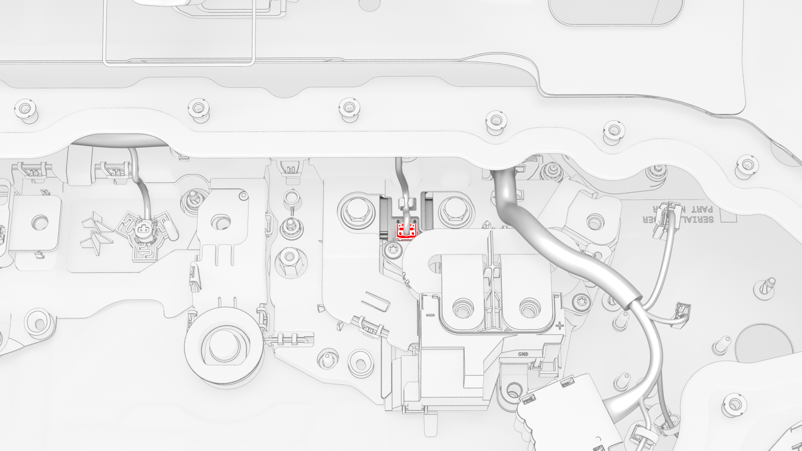
Release the clip that attaches the HV battery penthouse harness to the post near the LH UFO.
Note: Pull and unhook to release the flat rectangular clip.
-
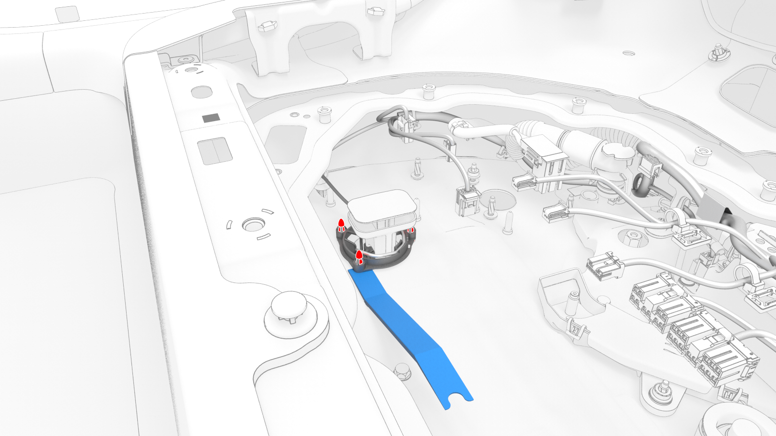
Use the UFO connector removal tool to disconnect the LH passthrough connector from the HV battery module 1 BMS connector.
Caution:Do not try to remove the LH passthrough in this step, as it will be damaged. Only disconnect the connector.Tip: Access the penthouse from the LH rear door area for this step.
-
Use a pry tool to release the LH passthrough clips (x3) that attach the LH passthrough to the posts of the penthouse floor, remove the passthrough, and then remove the HV battery penthouse harness from the vehicle.
| 1 | Perform the vehicle electrical isolation procedure. See Vehicle Electrical Isolation Procedure. | ||
| 2 | Drain the coolant from the power conversion system. See Penthouse Coolant (Drain and Refill). | ||
| 3 | Remove the penthouse cover. See Cover - Penthouse (Remove and Replace).Warning: HV insulating gloves and leather glove protectors must be worn throughout the remainder of this procedure. Do not remove gloves or protectors until otherwise noted. | ||
| 4 | Remove the pyrotechnic battery disconnect from the penthouse. See Pyrotechnic Battery Disconnect (Remove and Replace). | ||
| 5 | Remove the high voltage controller. See Controller - High Voltage (Remove and Replace). | ||
| 6 | Release the clips (x5) that attach the HV battery penthouse harness to the hinge tray. Note: Pull and unhook to release the flat rectangular clips.
| |
| 7 | Raise the hinge tray vertically, pull up on the tray at each hinge, and then remove the tray from the vehicle. | |
| 8 | Remove the power conversion system. See Power Conversion System (Remove and Replace). | ||
| 9 | Remove the HV battery negative contactor. See Contactor - Negative - HV Battery (Remove and Replace). | ||
| 10 | Remove the HV battery DC input assembly. See DC Input Assembly - HV Battery (Remove and Replace). | ||
| 11 | Remove the HV battery fast charge contactor from the penthouse. See Contactor - Fast Charge - HV Battery (Remove and Replace). Note: Do not disassemble the HV battery fast charge contactor assembly after removal.
| ||
| 12 | Remove the clip that confines the LH Hall-effect sensor to the LH flood port cover above the LH flood port. | |
| 13 | Release the tab that holds the LH Hall-effect sensor to the LH flood port cover, and then separate the sensor from under the tab. | |
| 14 | Remove the 12V DC passthrough. See Passthrough - DCDC - 12V (Remove and Replace). | ||
| 15 | Remove the HV battery positive contactor. See Contactor - Positive - HV Battery (Remove and Replace). | ||
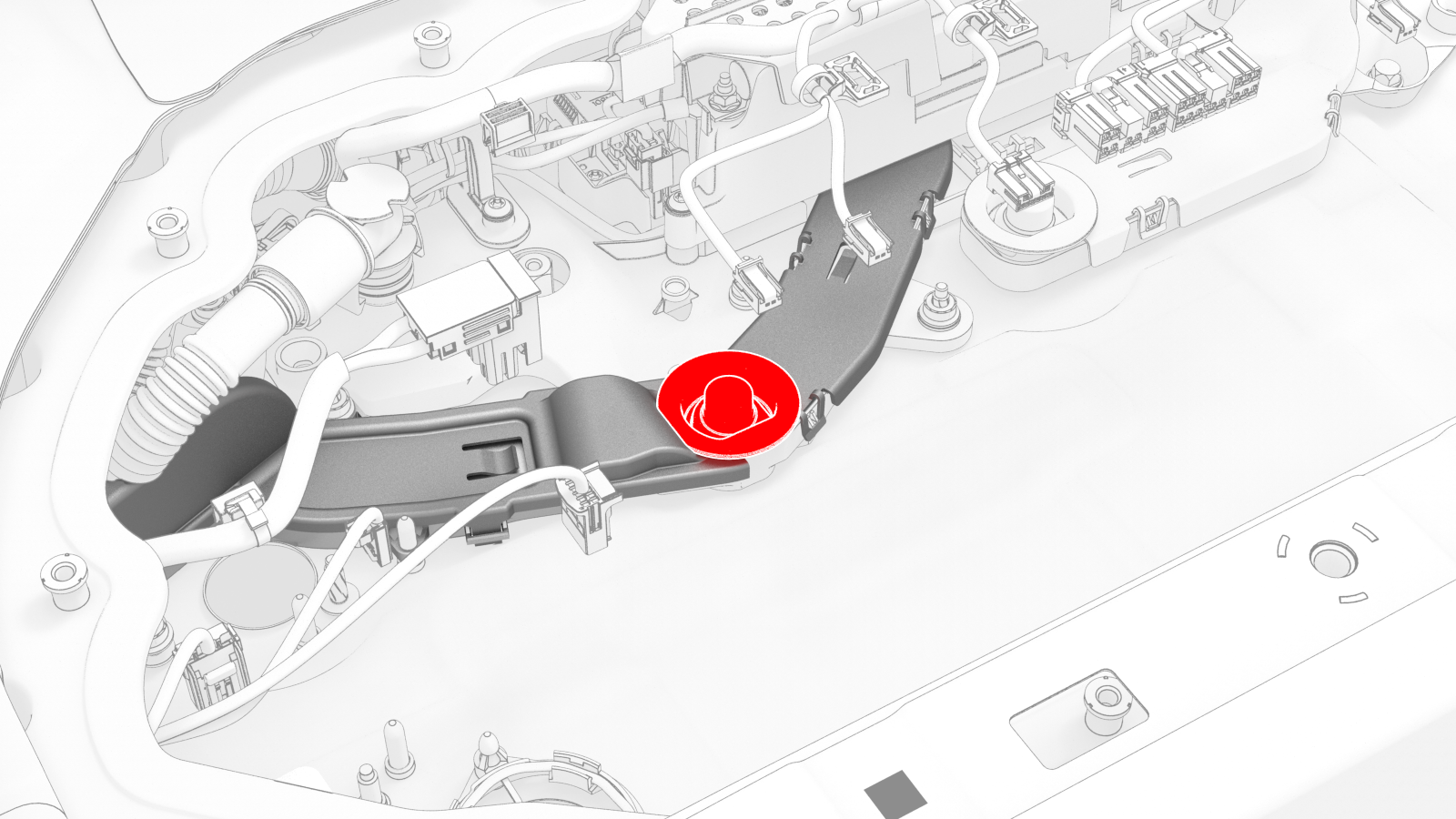
| 16 | Remove the insulator cap from the nut that joins the positive DC link to the positive busbar. | |
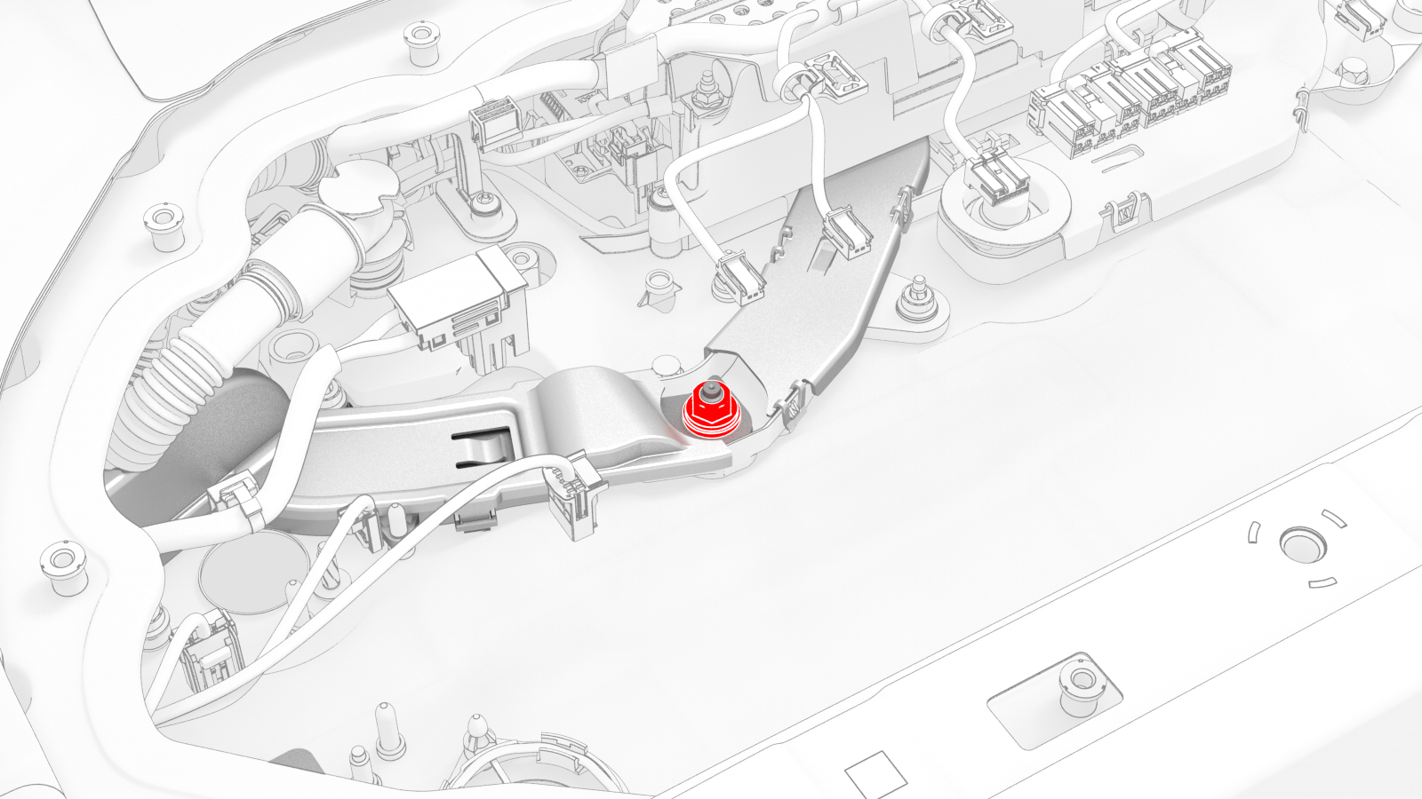
| 17 | Remove and discard the nut that joins the positive DC link to the positive busbar. | |
| 18 | Remove the nuts (x2) that attach the positive DC link to the penthouse floor, lift the link off of the studs and posts, and then move the link inboard to access the HV battery penthouse harness clips. | |
| 19 | Release the clips that attach the HV battery penthouse harness to the positive DC link insulator, and remove the DC link from the penthouse. Note: The rear most clip is behind the positive DC link insulator.
| |
View From RH Rear Door
| 20 | Use the UFO connector removal tool to disconnect the RH passthrough connector from the HV battery module 4 BMS connector. Caution: Do not try to remove the RH passthrough in this step, as it will be damaged. Only disconnect the connector.
Tip: Access the penthouse from the RH rear door area for this step. | |
| 21 | Use a pry tool to release the RH passthrough clips (x3) that attach the RH passthrough to the posts of the penthouse floor, and then separate the passthrough from the penthouse floor. | |
| 22 | Remove the clip that confines the RH Hall-effect sensor to the RH flood port cover above the RH flood port. | |
| 23 | Release the tab that holds the RH Hall-effect sensor to the RH flood port cover, and then separate the sensor from under the tab. | |
| 24 | Remove the cable ties that attach the HV battery penthouse harness to the power conversion system DC bus HV harness on either side of the RH Hall-effect sensor. | |
| 25 | Release the clips that attach the fuse access insulator to the RH penthouse bus cover, and remove the insulator. | |
| 26 | If installed, release the clips that attach the shunt access insulator over the shunt, and remove the insulator. | ||
| 27 | Release the clips (x4) that attach the HV battery penthouse harness along the busbar insulator. | |
| 28 | Release the HV battery penthouse harness from under the respective tabs, and disconnect the harness from the A/C compressor and PTC heater high voltage interlock loop connector , the rear drive unit high voltage interlock loop connector, and the shunt connector. | |
| 29 | Release the clips that attach the pyrotechnic battery disconnect connector to the penthouse floor, and separate the connector from the floor. | |
| 30 | If the vehicle is configured with dual motors, release the HV battery penthouse harness from under the tab, and disconnect the harness from the front drive unit high voltage interlock loop connector. | |
| 31 | Release the clip that attaches the HV battery penthouse harness to the post near the LH UFO. Note: Pull and unhook to release the flat rectangular clip.
| |
| 32 | Use the UFO connector removal tool to disconnect the LH passthrough connector from the HV battery module 1 BMS connector. Caution: Do not try to remove the LH passthrough in this step, as it will be damaged. Only disconnect the connector.
Tip: Access the penthouse from the LH rear door area for this step. | |
| 33 | Use a pry tool to release the LH passthrough clips (x3) that attach the LH passthrough to the posts of the penthouse floor, remove the passthrough, and then remove the HV battery penthouse harness from the vehicle. |
Install
-
Fasten the clip that attaches the HV battery penthouse harness to the post near the LH UFO.
-
If the vehicle is configured with dual motors, connect the HV battery penthouse harness to the front drive unit high voltage interlock loop connector, and then fasten the harness under the tab.
-
Install the pyrotechnic battery disconnect connector into the penthouse floor, and then fasten the clips that attach the connector to the floor.
-
Connect the HV battery penthouse harness to the shunt connector, the rear drive unit high voltage interlock loop connector, the A/C compressor and PTC heater high voltage interlock loop connector, and then fasten the harness under the respective tabs.
-
Fasten the clips (x4) that attach the HV battery penthouse harness along the busbar insulator.
-
Install the fuse access insulator to the RH penthouse bus cover, and then fasten the clips that attach the insulator to the cover.
-
Fasten the RH Hall-effect sensor under the tab of the RH flood port cover.
-
Install the clip that confines the RH Hall-effect sensor to the RH flood port cover above the RH flood port.
-
Install new cable ties on either side of the RH Hall-effect sensor to attach the HV battery penthouse harness to the power conversion system DC bus HV harness.
-
Bring the positive DC link to the penthouse, and then fasten the clips that attach the HV battery penthouse harness to the positive DC link insulator.
-
Install the positive DC link onto the studs and posts of the penthouse floor, and then install the nuts (x2) that attach the link to the floor.
 Torque 6 Nm
 -
Install a new nut to join the positive DC link to the positive busbar.
 Torque 9 Nm
 -
Install the insulator cap onto the nut that joins the positive DC link to the positive busbar.
-
Fasten the LH Hall-effect sensor under the tab of the LH flood port cover.
-
Install the clip that confines the LH Hall-effect sensor to the LH flood port cover above the LH flood port.
-
Install the hinge tray vertically onto the hinges, press down on the tray at each hinge so that the tray attaches to the hinges, and then lower the tray.
-
Fasten the clips (x5) that attach the HV battery penthouse harness to the hinge tray.
| 1 | Lay the HV battery penthouse harness down inside of the penthouse. Note: The large fast charge contactor connector goes on the LH side near the LH passthrough to the HV battery.
| ||
| 2 | Install the LH passthrough onto the posts at the LH penthouse floor, and then press the passthrough down to fasten the passthrough clips (x3). | ||
| 3 | Press the center of the LH passthrough to connect the passthrough connector to the HV battery module 1 BMS connector. | ||
| 4 | Fasten the clip that attaches the HV battery penthouse harness to the post near the LH UFO. | |
| 5 | If the vehicle is configured with dual motors, connect the HV battery penthouse harness to the front drive unit high voltage interlock loop connector, and then fasten the harness under the tab. | |
| 6 | Install the pyrotechnic battery disconnect connector into the penthouse floor, and then fasten the clips that attach the connector to the floor. | |
| 7 | Connect the HV battery penthouse harness to the shunt connector, the rear drive unit high voltage interlock loop connector, the A/C compressor and PTC heater high voltage interlock loop connector, and then fasten the harness under the respective tabs. | |
| 8 | Fasten the clips (x4) that attach the HV battery penthouse harness along the busbar insulator. | |
| 9 | If removed, install the shunt access insulator over the shunt, and then fasten the clips that attach the insulator to the shunt. | ||
| 10 | Install the fuse access insulator to the RH penthouse bus cover, and then fasten the clips that attach the insulator to the cover. | |
| 11 | Fasten the RH Hall-effect sensor under the tab of the RH flood port cover. | |
| 12 | Install the clip that confines the RH Hall-effect sensor to the RH flood port cover above the RH flood port. | |
| 13 | Install new cable ties on either side of the RH Hall-effect sensor to attach the HV battery penthouse harness to the power conversion system DC bus HV harness. | |
| 14 | Install the RH passthrough onto the posts at the RH penthouse floor, and then press the passthrough down to fasten the passthrough clips (x3). | ||
| 15 | Press the center of the RH passthrough to connect the passthrough connector to the HV battery module 4 BMS connector. | ||
| 16 | Bring the positive DC link to the penthouse, and then fasten the clips that attach the HV battery penthouse harness to the positive DC link insulator. | |
| 17 | Install the positive DC link onto the studs and posts of the penthouse floor, and then install the nuts (x2) that attach the link to the floor. Torque 6 Nm | |
| 18 | Install a new nut to join the positive DC link to the positive busbar. Torque 9 Nm | |
| 19 | Install the insulator cap onto the nut that joins the positive DC link to the positive busbar. | |
| 20 | Install the HV battery positive contactor. See Contactor - Positive - HV Battery (Remove and Replace). | ||
| 21 | Install the 12V DC passthrough. See Passthrough - DCDC - 12V (Remove and Replace). | ||
| 22 | Fasten the LH Hall-effect sensor under the tab of the LH flood port cover. | |
| 23 | Install the clip that confines the LH Hall-effect sensor to the LH flood port cover above the LH flood port. | |
| 24 | Install the HV battery fast charge contactor into the penthouse. See Contactor - Fast Charge - HV Battery (Remove and Replace). | ||
| 25 | Install the HV battery DC input assembly. See DC Input Assembly - HV Battery (Remove and Replace). | ||
| 26 | Install the HV battery negative contactor. See Contactor - Negative - HV Battery (Remove and Replace). | ||
| 27 | Install the power conversion system, perform a penthouse coolant leak test, and refill the coolant. See Power Conversion System (Remove and Replace). | ||
| 28 | Install the hinge tray vertically onto the hinges, press down on the tray at each hinge so that the tray attaches to the hinges, and then lower the tray. | |
| 29 | Fasten the clips (x5) that attach the HV battery penthouse harness to the hinge tray. | |
| 30 | Install the high voltage controller. See Controller - High Voltage (Remove and Replace). | ||
| 31 | Install the pyrotechnic battery disconnect into the penthouse. See Pyrotechnic Battery Disconnect (Remove and Replace). | ||
| 32 | Install the penthouse cover, perform a penthouse air leak test, and connect 12V power. See Cover - Penthouse (Remove and Replace). |