Four Wheel Alignment (Check and Adjust)
Correction code 3100020031000200
- 1096767-00-ASEAT COVER
- 1145158-00-ABallast Bag, 25lb
- 1071271-00-ACHASSIS HEIGHT MEASURING TOOL
- 1049463-00-ASTEERING WHEEL LEVEL
SPECIAL TOOLS
SEAT COVER (1096767-00-A) |
Ballast Bag, 25lb (1145158-00-A) |
CHASSIS HEIGHT MEASURING TOOL (1071271-00-A) |
STEERING WHEEL LEVEL (1049463-00-A) |
Prepare for Adjustment
-
Disconnect the charging cable from the vehicle.
 Warning: Do not attach the charging cable to the charge port while the vehicle is on the rack.
 -
Check the torque on the bolt and nut that attach LH and RH front lower lateral links to the LH and RH strut assemblies.
 Torque 106 Nm
 Torque 106 Nm
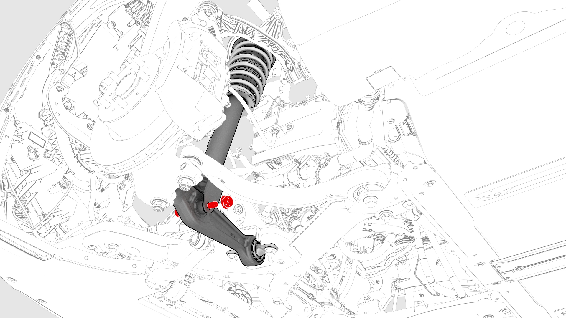
-
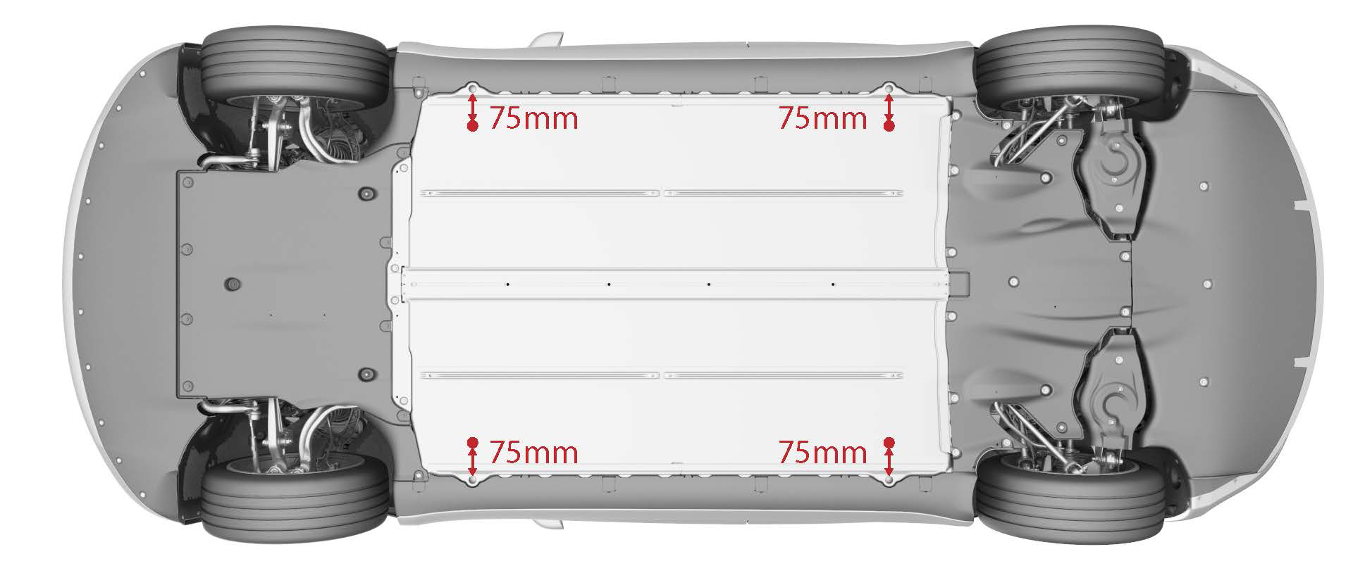
Measure the ride height at 4 locations which are an additional 75 mm towards the centerline from the vehicle lifting points.
| 1 | Make sure the tire pressures are to specification. Note: Use the tire sticker values displayed on the door jam. If unavailable, use these values:
| ||
| 2 | Make sure that the alignment rack slip/turn plates are locked. | ||
| 3 | Disconnect the charging cable from the vehicle.Warning: Do not attach the charging cable to the charge port while the vehicle is on the rack. | ||
| 4 | Drive the vehicle onto the alignment rack, and stop the vehicle approximately 6 inches before the turn plates to allow for rolling compensation. | ||
| 5 | Shift into Park. | ||
| 6 | Install wheel chocks. | ||
| 7 | Install seat covers on the driver and front passenger seats. | ||
| 8 | Set 150 pounds of ballast bags onto the driver seat, and 150 pounds of ballast bags onto the front passenger seat. | ||
| 9 | From outside of the vehicle, fasten the driver and front passenger seat belts, and shift into Neutral. | ||
| 10 | Pass a shop towel halfway through the both door strikers, and use a pen to latch the doors. | ||
| 11 | Raise the alignment rack to a working height and slightly lower to lock. | ||
| 12 | Check the torque on the bolt and nut that attach LH and RH front lower lateral links to the LH and RH strut assemblies. Torque 106 Nm Torque 106 Nm | |
| 13 | Install the alignment heads onto the wheels. | ||
| 14 | Type the vehicle information into the alignment machine. | ||
| 15 | Perform a rolling compensation and manually position the vehicle onto the slip/turn plates. | ||
| 16 | Remove the alignment slip/turn plate pins. | ||
| 17 | Calibrate the ride height tool. | ||
| 18 | Measure the ride height at 4 locations which are an additional 75 mm towards the centerline from the vehicle lifting points. | |
| 19 | Move the front seats fore and aft to set the following ride heights:
| ||
| 20 | Install the brake pedal depressor and steering wheel bubble leveler. | ||
| 21 | Perform a caster sweep, center and set the steering wheel using the bubble leveler and steering wheel holder. | ||
| 22 | Print the vehicle summary and identify which alignment parameters are not within specifications. Note: If the alignment parameters are within specifications, go to step 2 of Complete the Alignment.
| ||
| 23 | Raise the alignment rack to an overhead height and slightly lower to lock. | ||
| 24 | Remove the mid aero shield panel. See Panel - Aero Shield - Mid (Remove and Replace). | ||
| 25 | Adjust the rear camber. See Adjust Rear Camber. |
Adjust Rear Camber
-
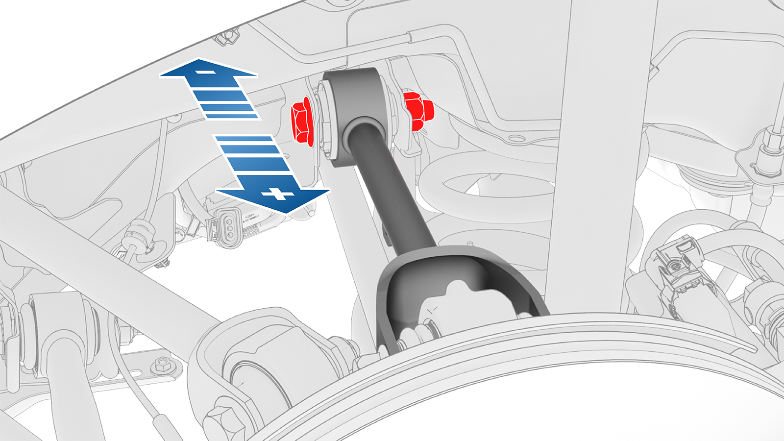
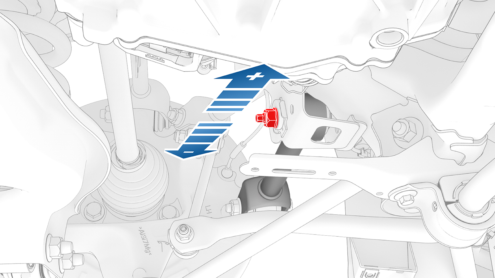
Slightly loosen, but do not remove, the rear LH lower aft link to knuckle bolt.
-
Slightly loosen, but do not remove, the rear LH lower aft link to subframe bolt.
-
Slightly loosen, but do not remove, the rear LH upper aft link to subframe bolt.
-
Tighten the suspension bolts that were loosened.
 Torque Lower Aft Link to Knuckle Bolt 115NmTorque Lower Aft Link to Subframe Bolt 115 NmTorque Upper Aft Link to Subframe Bolt 134 Nm
| 1 | If the rear camber is within specification and does not require adjustment, adjust the rear toe. See Adjust Rear Toe. | ||
| 2 | Slightly loosen, but do not remove, the rear LH lower aft link to knuckle bolt. | |
| 3 | Adjust the rear LH camber to -1.00° +/- 1.0° (+/- 0.80° split).
| ||
| 4 | If the camber is correct, go to step 11. | ||
| 5 | Slightly loosen, but do not remove, the rear LH lower aft link to subframe bolt. | |
| 6 | Adjust the rear LH camber to -1.00° +/- 1.0° (+/- 0.80° split).
| ||
| 7 | If the camber is correct, go to step 11. | ||
| 8 | Slightly loosen, but do not remove, the rear LH upper aft link to subframe bolt. | |
| 9 | Adjust the rear LH camber to -1.00° +/- 1.0° (+/- 0.80° split).
| ||
| 10 | If the camber cannot be corrected, escalate a Toolbox session. | ||
| 11 | Tighten the suspension bolts that were loosened. Torque Lower Aft Link to Knuckle Bolt 115Nm Torque Lower Aft Link to Subframe Bolt 115 Nm Torque Upper Aft Link to Subframe Bolt 134 Nm | ||
| 12 | Perform step 2 through step 11 for the RH side of the vehicle if necessary. | ||
| 13 | Adjust the rear toe. See Adjust Rear Toe. |
Adjust Rear Toe
-
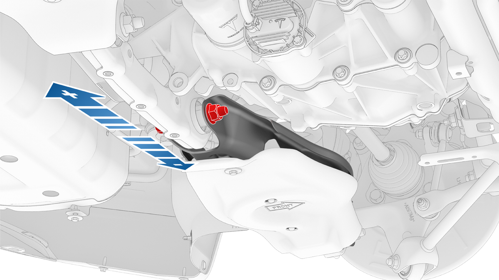
Loosen the nut on the rear LH toe link to subframe bolt.
-
When the rear LH toe is correct, tighten the nut.Torque 85 Nm
| 1 | If the rear toe is within specification and does not require adjustment, adjust the front camber and caster. See Adjust Front Camber and Caster. | ||
| 2 | Loosen the nut on the rear LH toe link to subframe bolt. | |
| 3 | Rotate the rear LH toe link to subframe bolt to adjust the rear LH toe to 0.20° IN +/- 0.15° (+/- 0.1.° split).
| ||
| 4 | When the rear LH toe is correct, tighten the nut. Torque 85 Nm | ||
| 5 | Perform step 2 through step 4 for the RH side of the vehicle if necessary. | ||
| 6 | Adjust the front camber and caster. See Adjust Front Camber and Caster. |
Adjust Front Camber and Caster
-
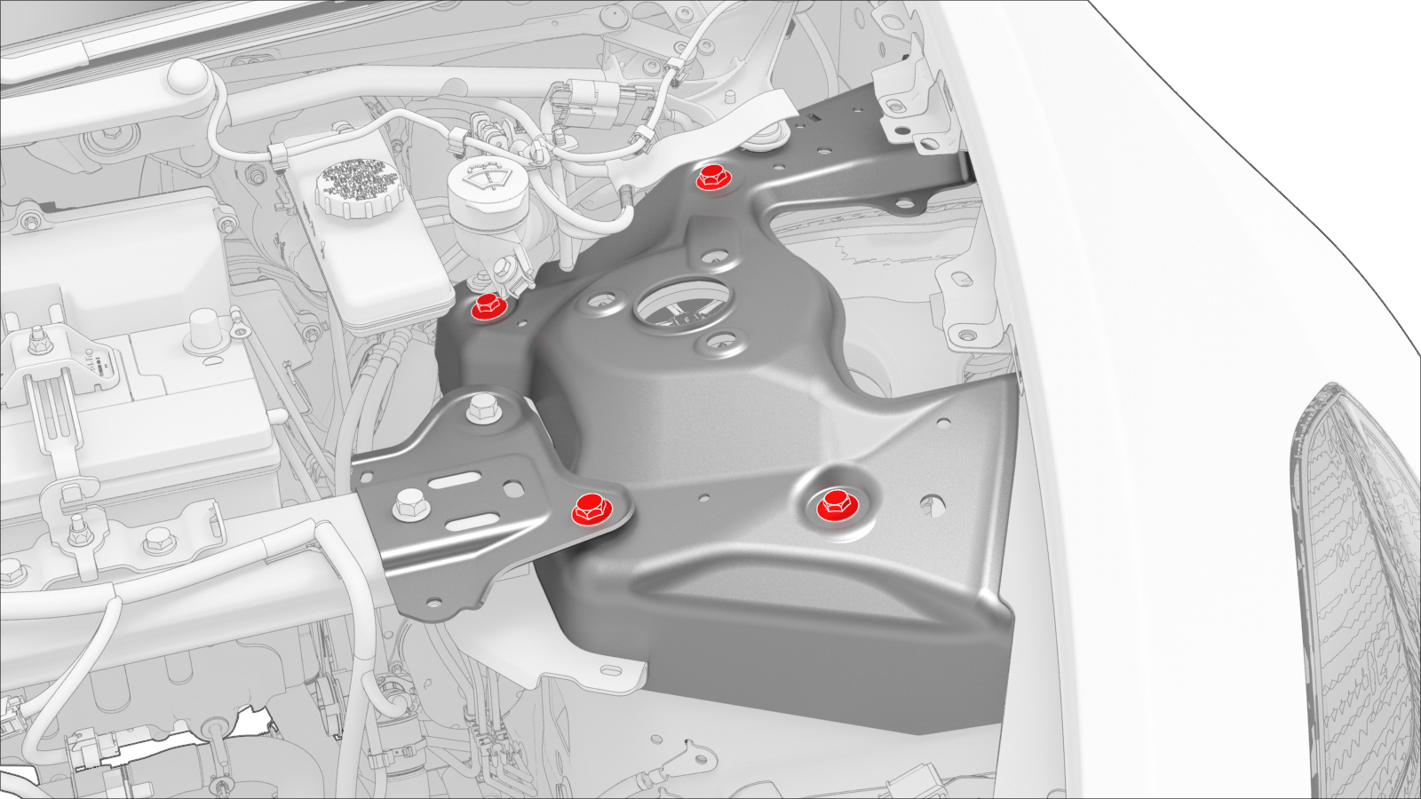
Slightly loosen, but do not remove, the LH FUCA mount bolts.
-
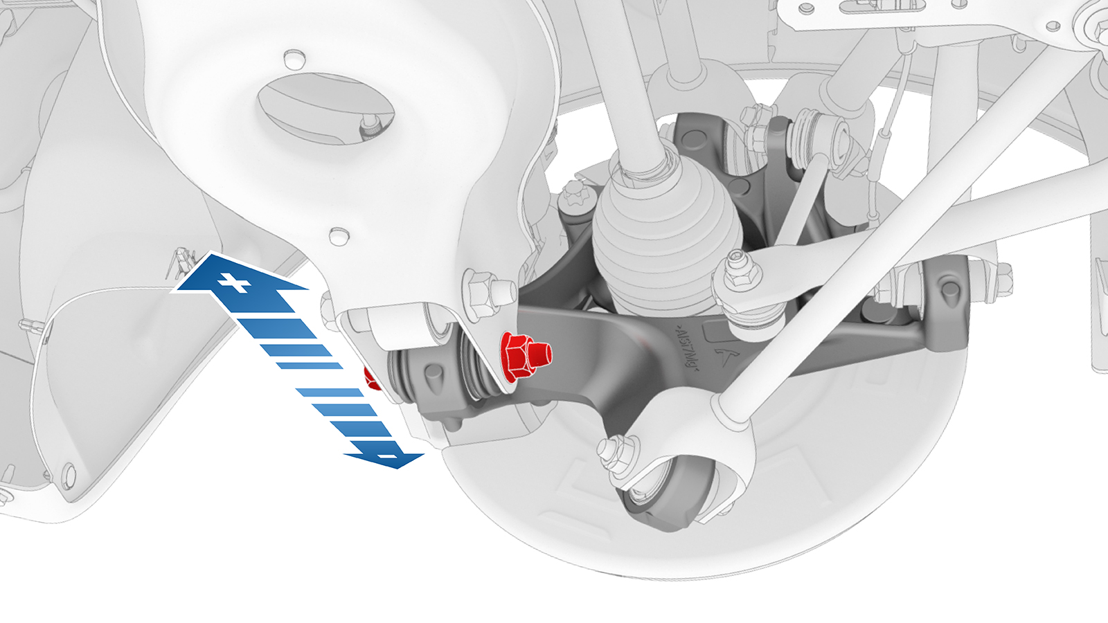
Adjust the front LH camber to -0.50° +/- 0.45° (+/- 0.60° split) and the LH caster to +5.7° +/- 1.0° (+/- 1.0° split).
- Negative Caster
- Negative Camber
- Positive Caster
- Positive Camber
-
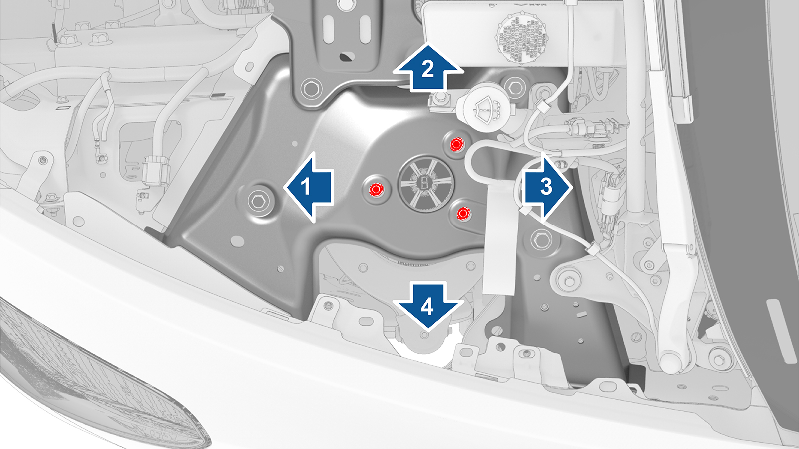
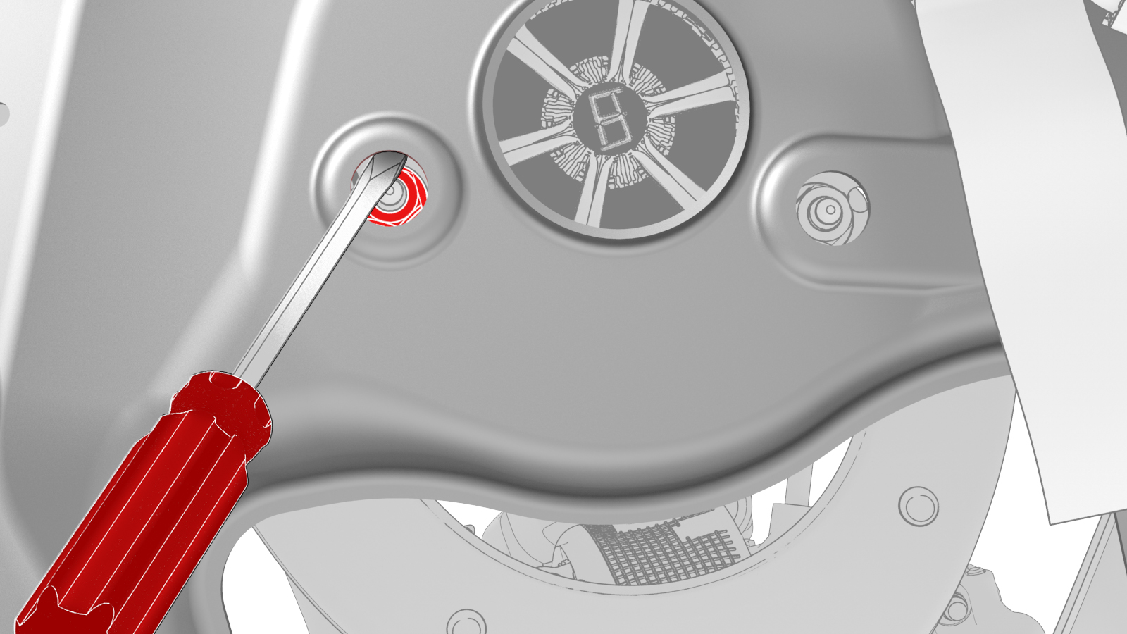
Use a pry tool or large screwdriver to pry between the damper mounting nuts and body openings, so as to move the FUCA mount inside the shock tower.
- Moving the FUCA mount out from the centerline makes positive camber.
- Moving the FUCA mount in toward the centerline makes negative camber.
- Moving the FUCA mount to the rear makes positive caster.
- Moving the FUCA mount to the front makes negative caster.
-
When the front LH camber and LH caster are at the correct setting, have an assistant tighten the FUCA mount bolts to hold the position.Torque 30 Nm
-
When the front LH camber and LH caster are correct, tighten the larger LH FUCA mount bolts.
 Torque 62 Nm
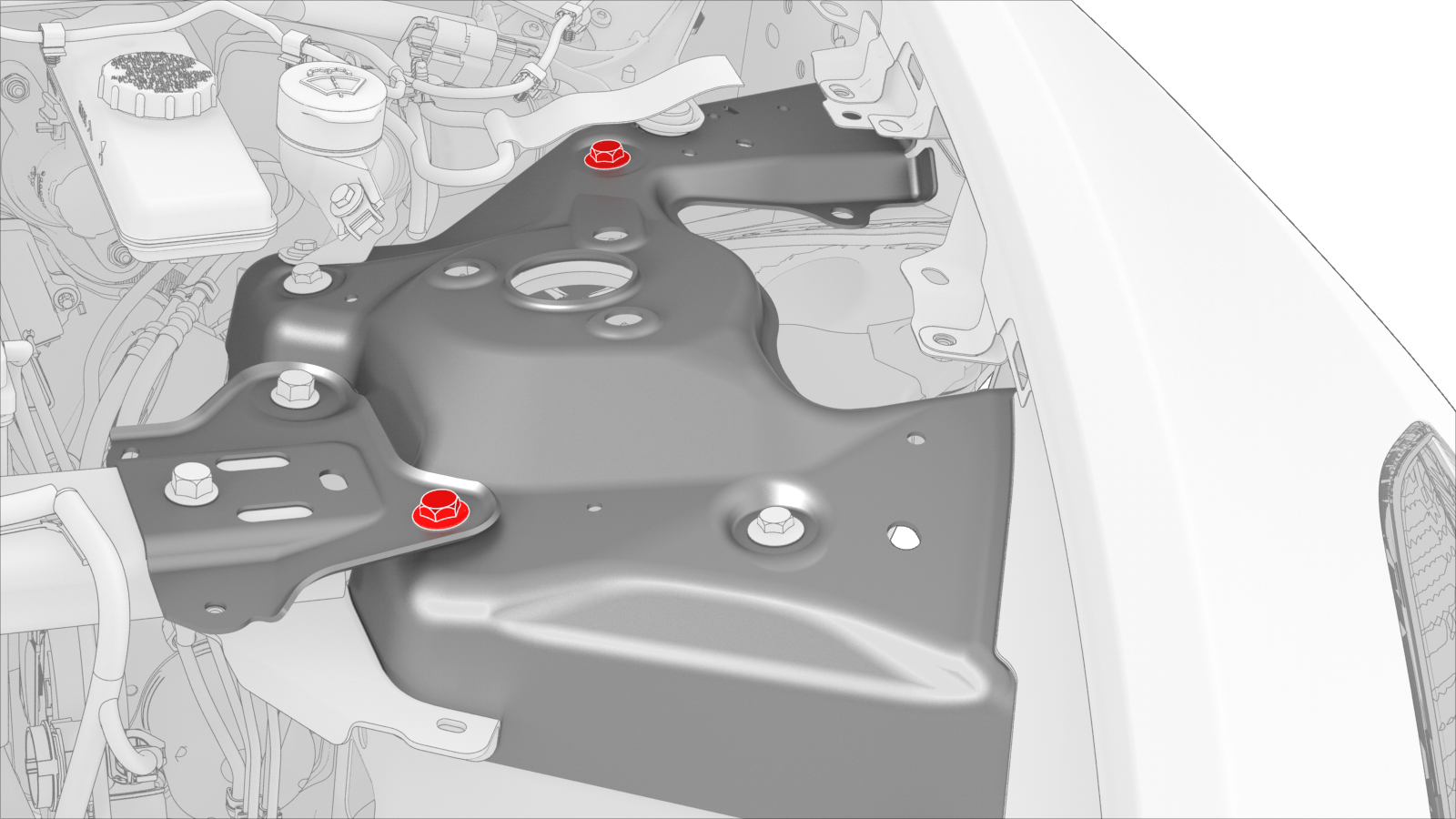
-
Tighten the smaller LH FUCA mount bolts.
 Torque 35 Nm
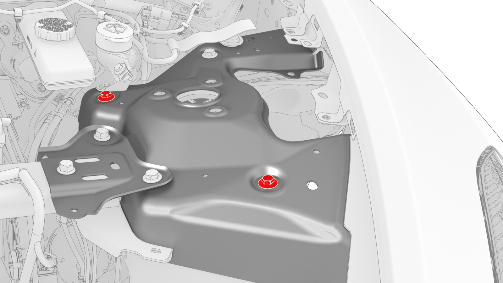
| 1 | If the front camber and caster are within specification and do not require adjustment, adjust the front toe. See Adjust Front Toe. | ||||||||||
| 2 | Remove the cowl screen panel. See Panel - Cowl Screen (Remove and Replace). | ||||||||||
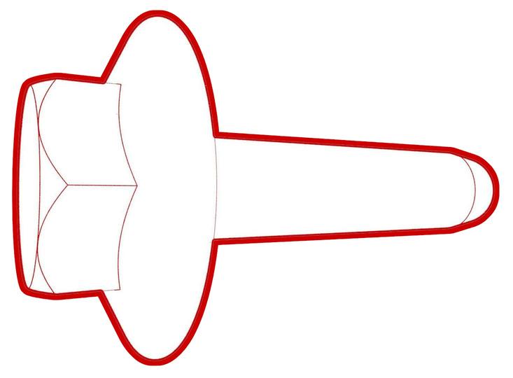
| 3 | Mark the location of the LH FUCA mount bolts by drawing a circle around each. Note: The circles provide a reference for the adjustment process.
| ||||||||||
| 4 | Slightly loosen, but do not remove, the LH FUCA mount bolts. | |||||||||
| 5 | Adjust the front LH camber to -0.50° +/- 0.45° (+/- 0.60° split) and the LH caster to +5.7° +/- 1.0° (+/- 1.0° split). | |||||||||
| 6 | Use a pry tool or large screwdriver to pry between the damper mounting nuts and body openings, so as to move the FUCA mount inside the shock tower.
| |||||||||
| 7 | When the front LH camber and LH caster are at the correct setting, have an assistant tighten the FUCA mount bolts to hold the position. Torque 30 Nm | |||||||||
| 8 | Perform a caster sweep, center and set the steering wheel, and check the alignment. | ||||||||||
| 9 | Repeat step 3 through step 8 as necessary. | ||||||||||
| 10 | When the front LH camber and LH caster are correct, tighten the larger LH FUCA mount bolts. Torque 62 Nm | |||||||||
| 11 | Tighten the smaller LH FUCA mount bolts. Torque 35 Nm | |||||||||
| 12 | Perform step 3 through step 11 for the RH side of the vehicle if necessary. | ||||||||||
| 13 | Adjust the front toe. See Adjust Front Toe. |
Adjust Front Toe
-
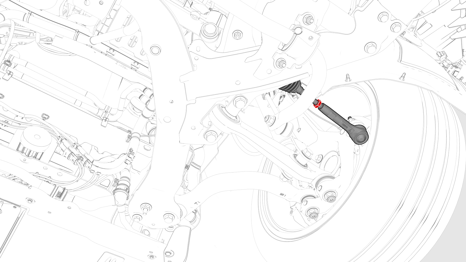
Loosen the jam nut on the LH inner tie rod.
-
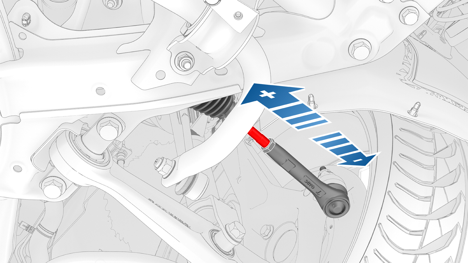
Rotate the LH inner tie rod to adjust the front LH toe to 0.05° OUT +/- 0.15° (+/- 0.10° split).
- To add positive toe in, move the tie rod end in toward the centerline.
- To add negative toe out, move the tie rod end out from the centerline.
-
When the front LH toe is correct, tighten the jam nut on the LH inner tie rod.Torque 80 Nm
| 1 | If the front toe is within specification and does not require adjustment, complete the alignment. See Complete the Alignment. | ||
| 2 | Loosen the jam nut on the LH inner tie rod. | |
| 3 | Rotate the LH inner tie rod to adjust the front LH toe to 0.05° OUT +/- 0.15° (+/- 0.10° split).
| |
| 4 | When the front LH toe is correct, tighten the jam nut on the LH inner tie rod. Torque 80 Nm | ||
| 5 | Perform step 2 through step 4 for the RH side of the vehicle if necessary. | ||
| 6 | Complete the alignment. See Complete the Alignment. |
Complete the Alignment
| 1 | Print the vehicle summary and verify that the alignment parameters are within specifications. Note:
Repeat the adjustment for any parameter that is not within specification. |
| 2 | Install the mid aero shield panel. See Panel - Aero Shield - Mid (Remove and Replace). |
| 3 | Lower the alignment rack to a working height and lock. |
| 4 | Remove the alignment heads from the wheels. |
| 5 | Remove the brake pedal depressor. |
| 6 | Install the alignment slip/turn plate pins. |
| 7 | Lower the alignment rack to the ground. |
| 8 | Unlatch the driver's door, shift into Park, and remove the steering wheel bubble leveler. |
| 9 | Unbuckle the seat belts and remove the ballast bags from the vehicle. |
| 10 | Remove the seat covers from the seats. |
| 11 | Connect a laptop with Toolbox 3 to the vehicle. |
| 12 | In Toolbox, click Actions, type "angle" in the search field, click Play to the left of "PROC_EPAS3X_X_CLEAR-APPLIED-ANGLE-OFFSET", and then select Run. |
| 13 | Click Actions, type "angle" in the search field, click Play to the left of "TEST_EPAS3P_X_CHECK-APPLIED-ANGLE-OFFSET", and then select Run. |
| 14 | Disconnect the laptop from the vehicle. |
| 15 | Remove the wheel chocks. |
| 16 | Install the cowl screen panel. See Panel - Cowl Screen (Remove and Replace). |
| 17 | Remove the vehicle from the alignment rack. |
| 18 | Perform a test drive and verify vehicle operation. |