Subframe Assembly - Rear (Remove and Install)
Correction code 3001020130010201
- 1134520-00-A Kit, EPB Release, Handheld
- 1129348-00-AXP-10 Power Supply, XP-10
- 1099645-00-BFixture, Subframe, Model 3
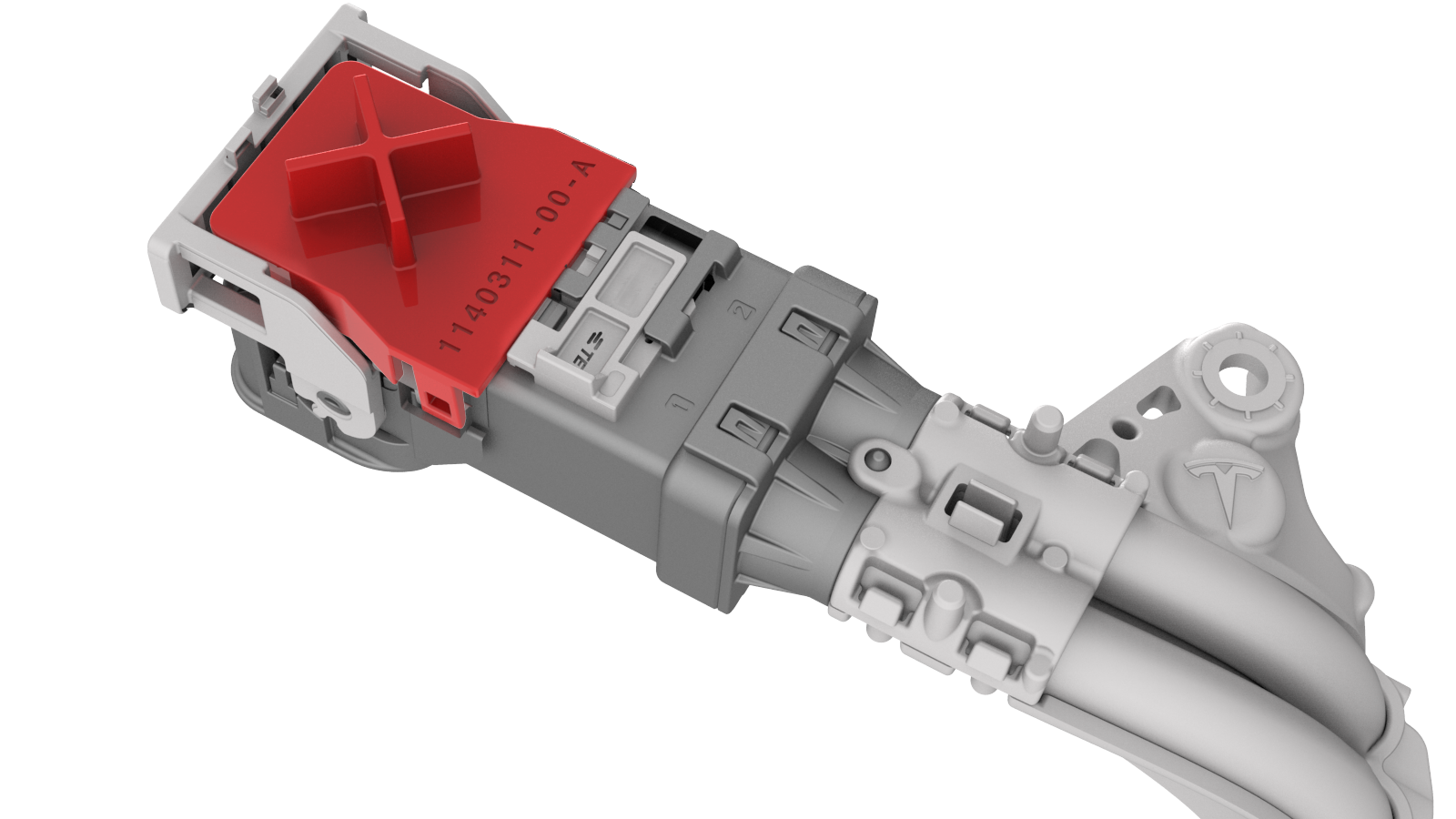
- 1140311-00-ALever Lock, HV Connector, Model 3
SPECIAL TOOLS
Kit, EPB Release, Handheld (1134520-00-A) |
XP-10 Power Supply, XP-10 (1129348-00-A) |
Fixture, Subframe, Model 3 (1099645-00-B) |
Lever Lock, HV Connector, Model 3 (1140311-00-A) |
Remove
-
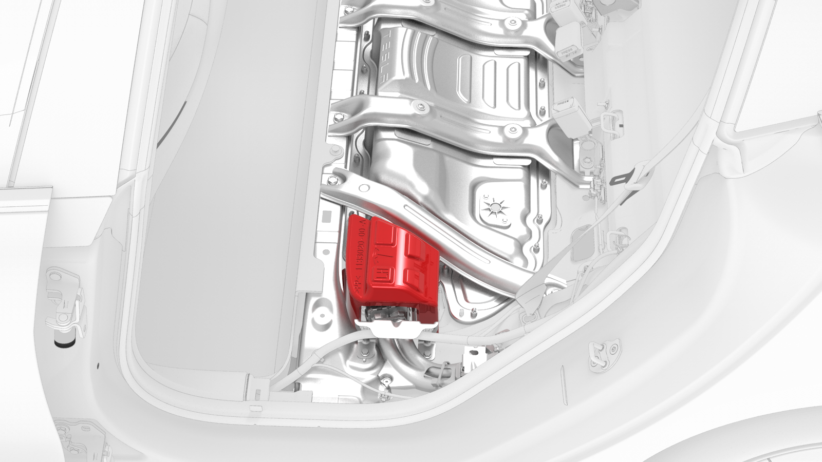
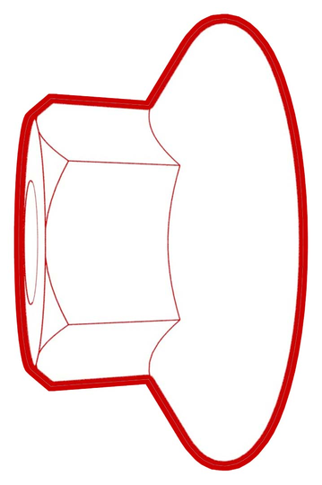
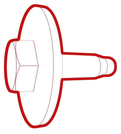
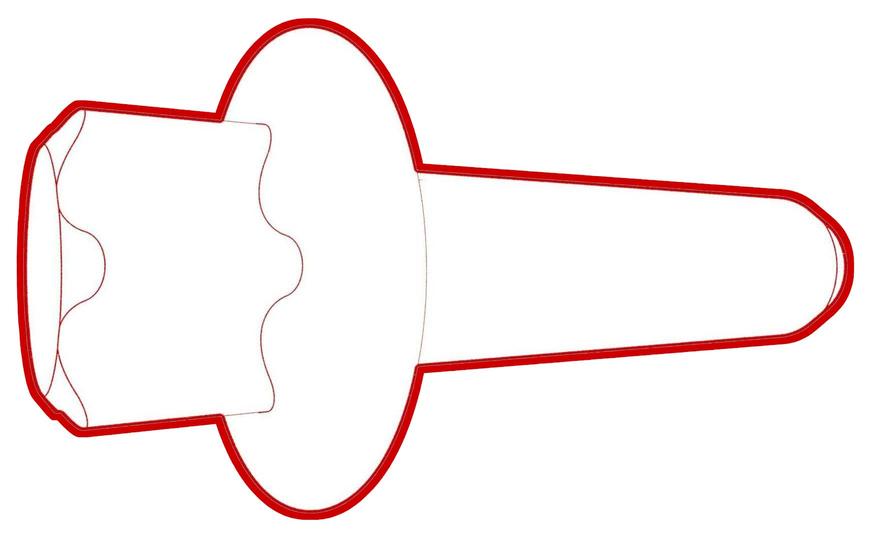
Remove the HV cap that covers the HV harness located on the LH side of the penthouse.
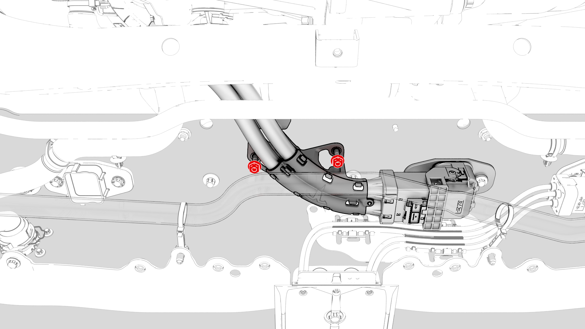
-
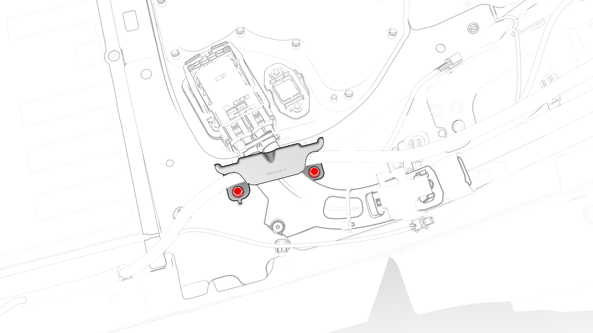
Remove the bolts that attach the wiring harness bracket at the penthouse.
-
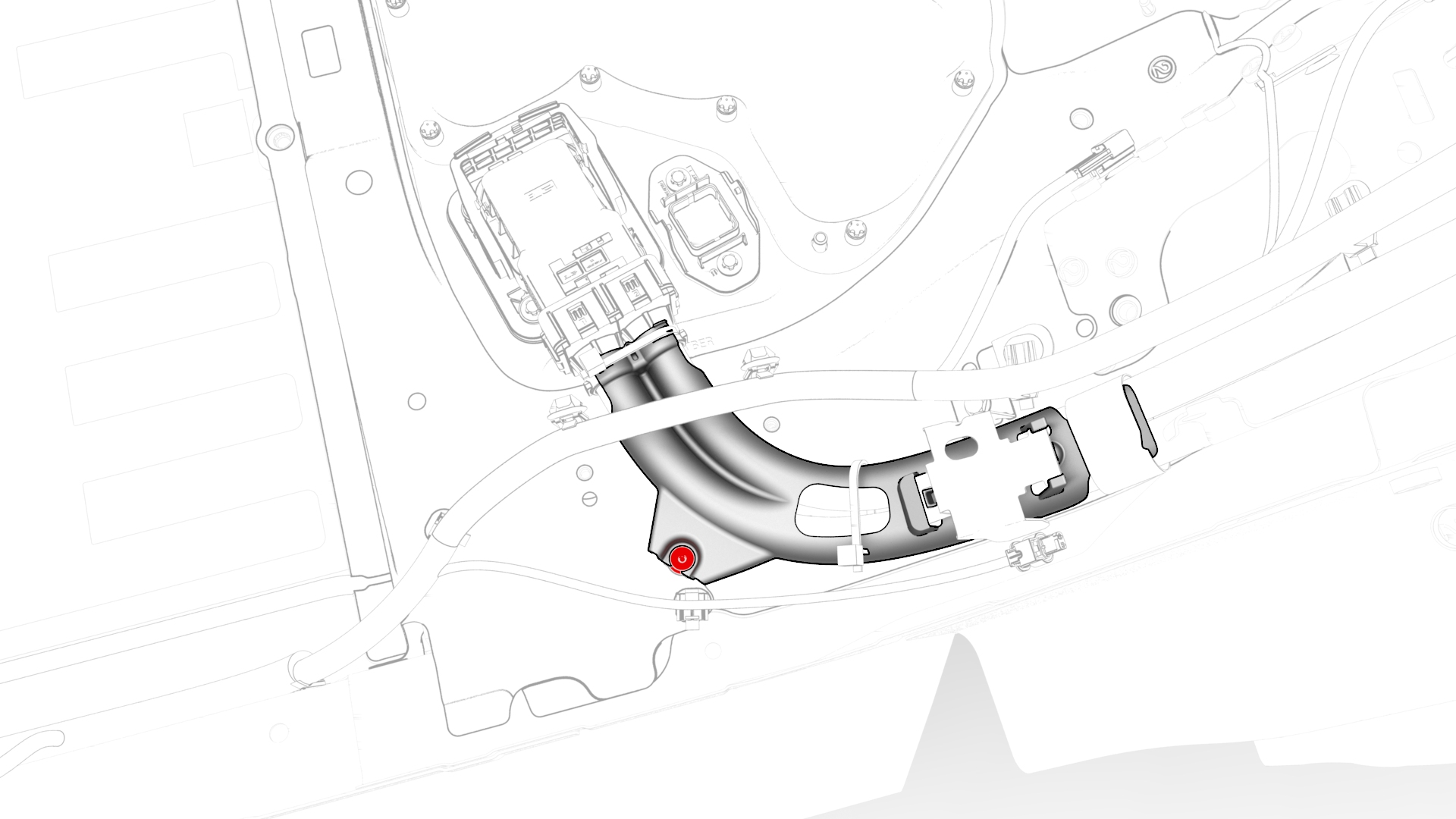
Release the clip that attaches the wiring harness to the LH lower C-pillar.
-
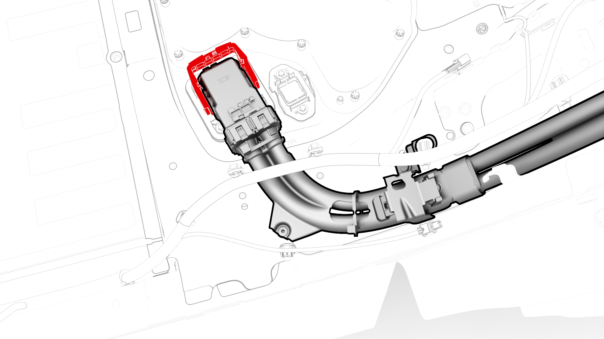
Raise the handle to disconnect the electrical harness from the DC Input assembly.
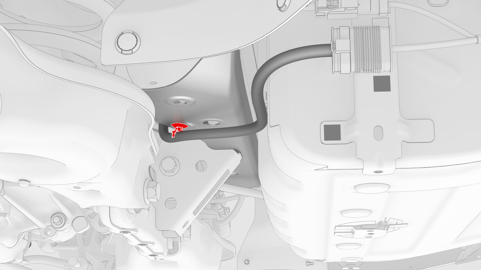
-
Disconnect the electrical connector from the LH rear brake caliper.
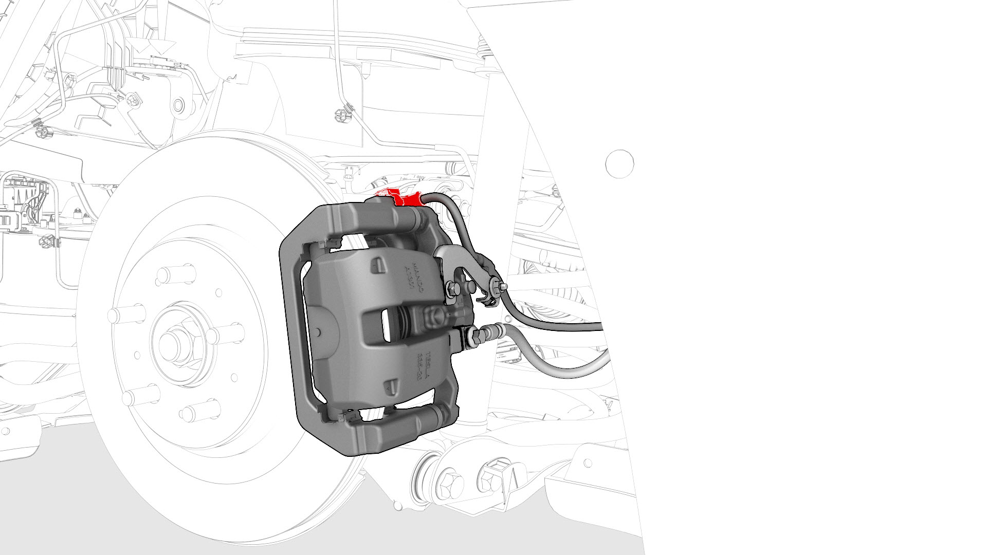 LH shown, RH similar
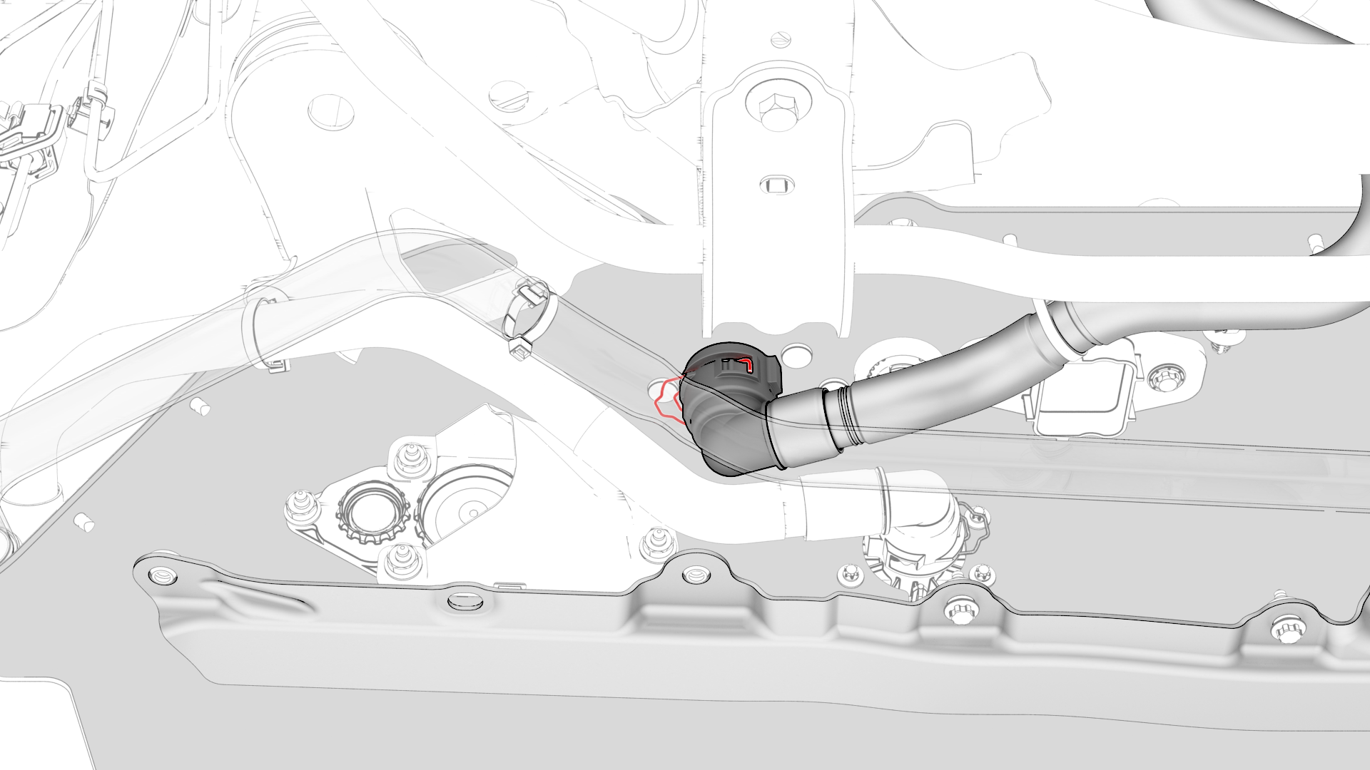
 -
Check the LH rear upper aft link and if present, disconnect the electrical connector from the sensor.
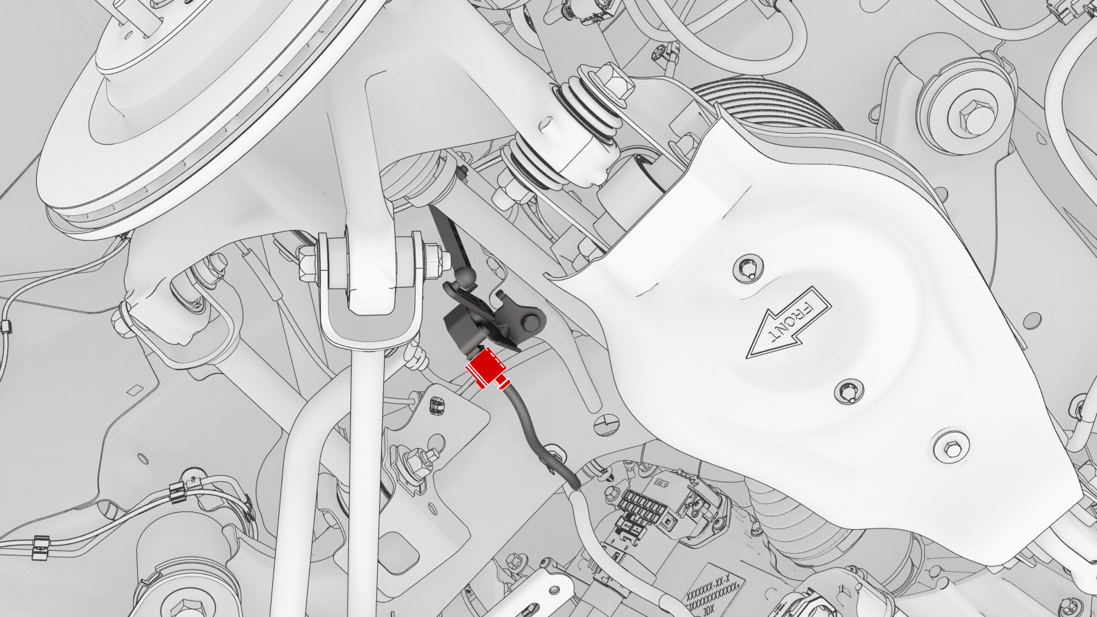 LH shown, RH similar
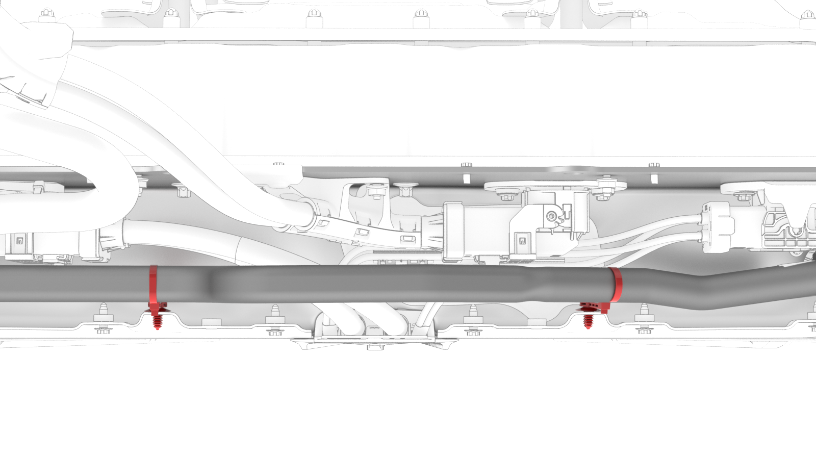
 -
If a connector was disconnected in the previous step, release the clip that attaches the connector harness to the underside of the rear subframe.
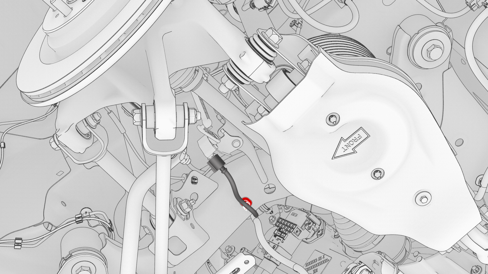 LH shown, RH similar
 -
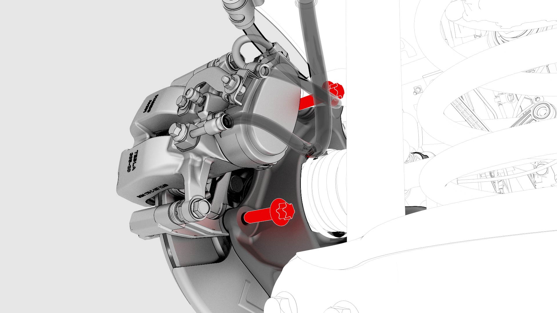
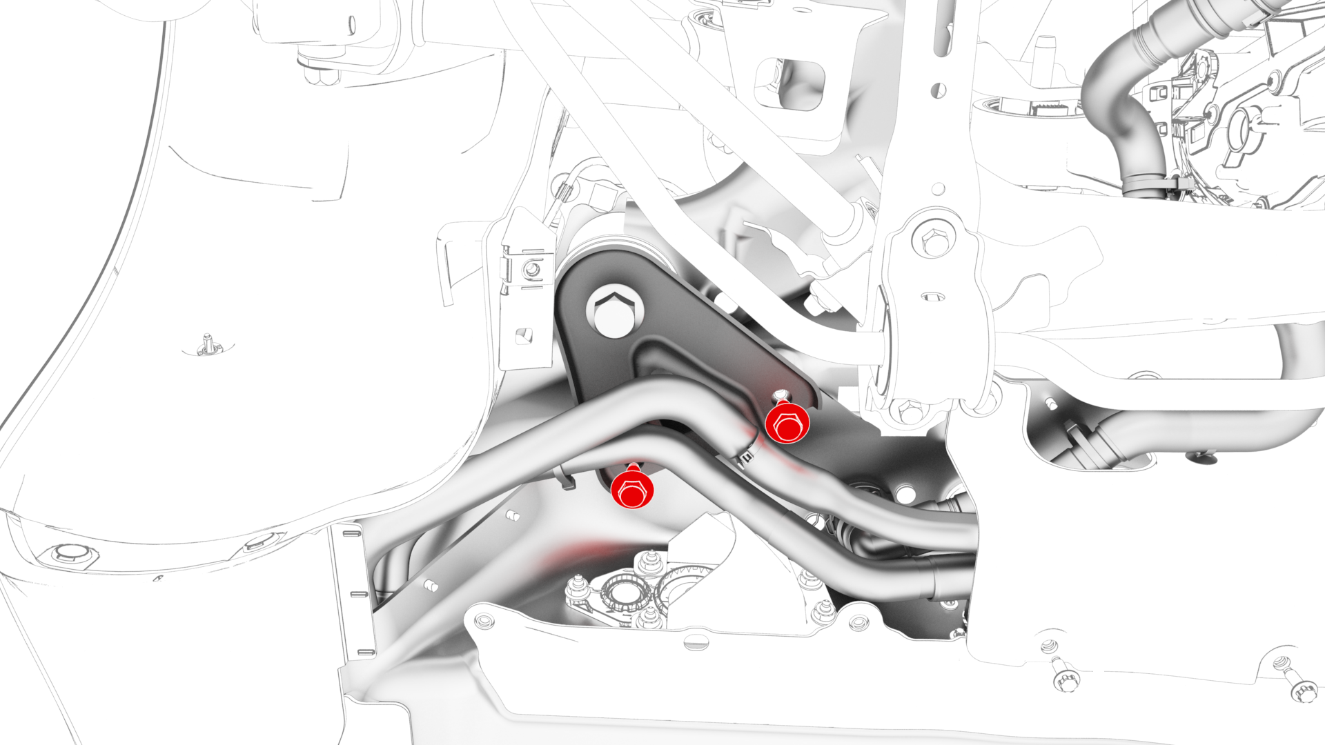
Remove the bolts that attach the LH rear brake caliper bracket to the knuckle, and then hang the caliper bracket on the body with an S-hook.
-
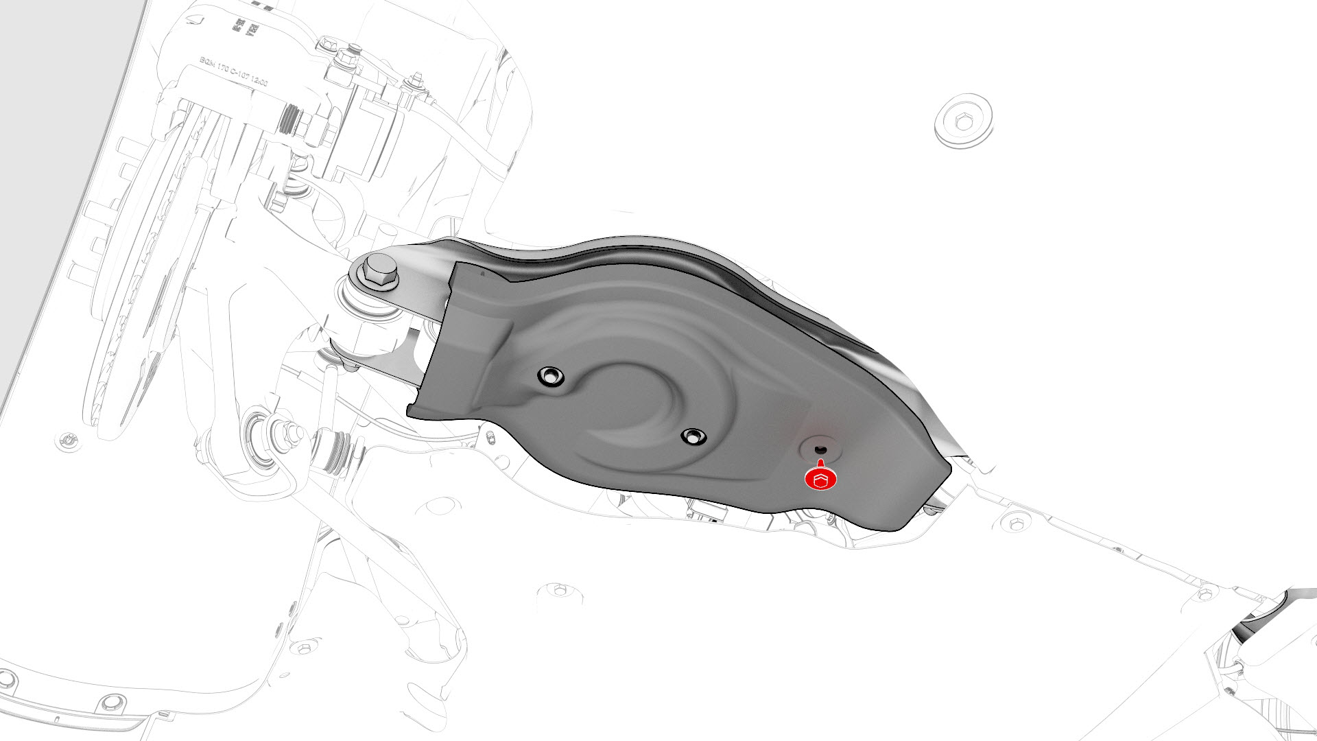
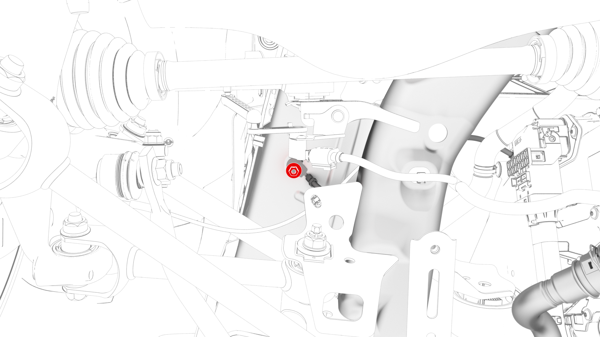
Remove the bolt that attaches the cover to the LH lower aft link, and then remove the cover from the vehicle.
-
Install a spring compressor onto the LH rear coil spring.
 Caution:Line up the hooks per image and verify that the threaded shaft goes through the body opening when the suspension is compressed.
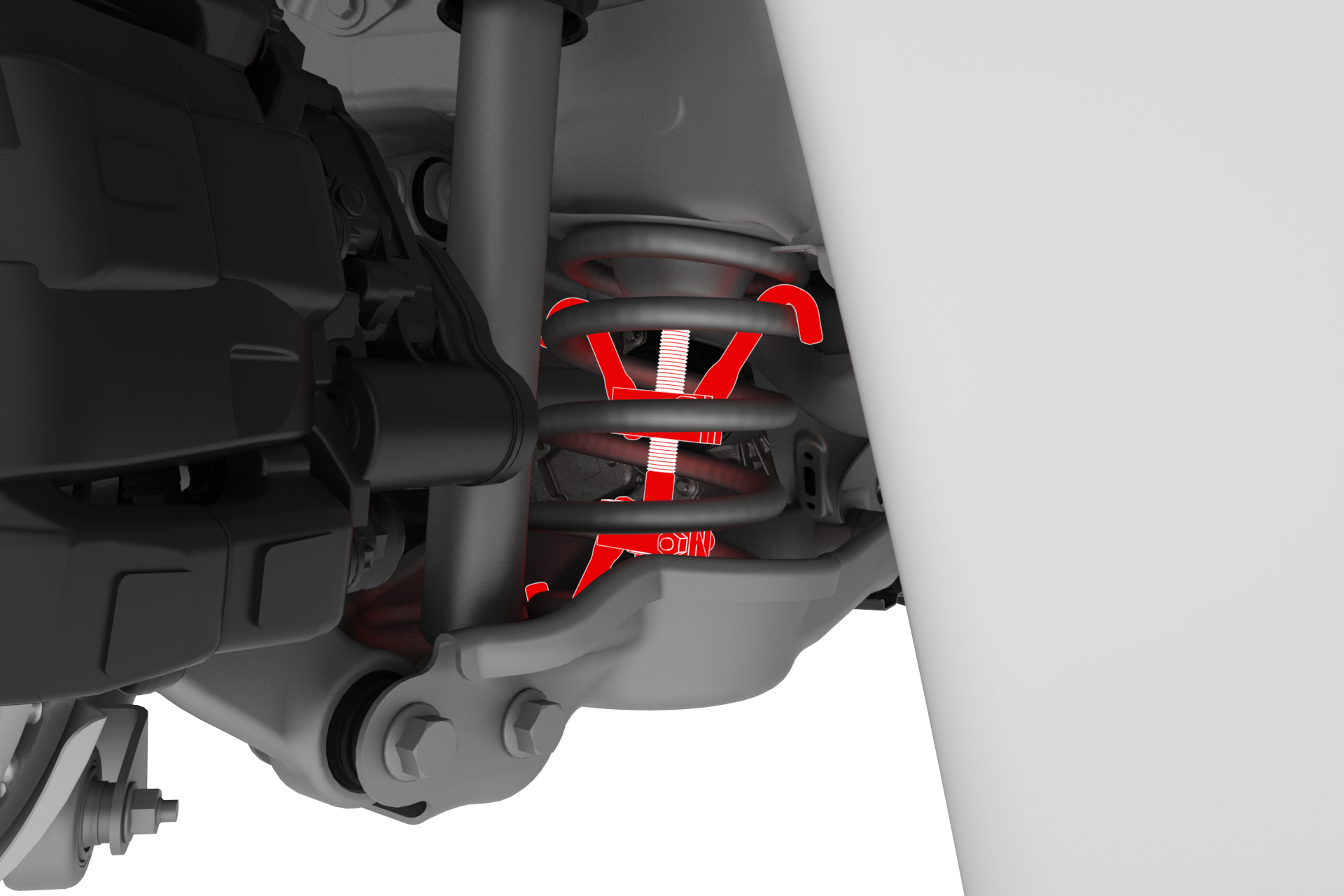
-
Remove the bolts that attach the LH rear damper at the top mount.

-
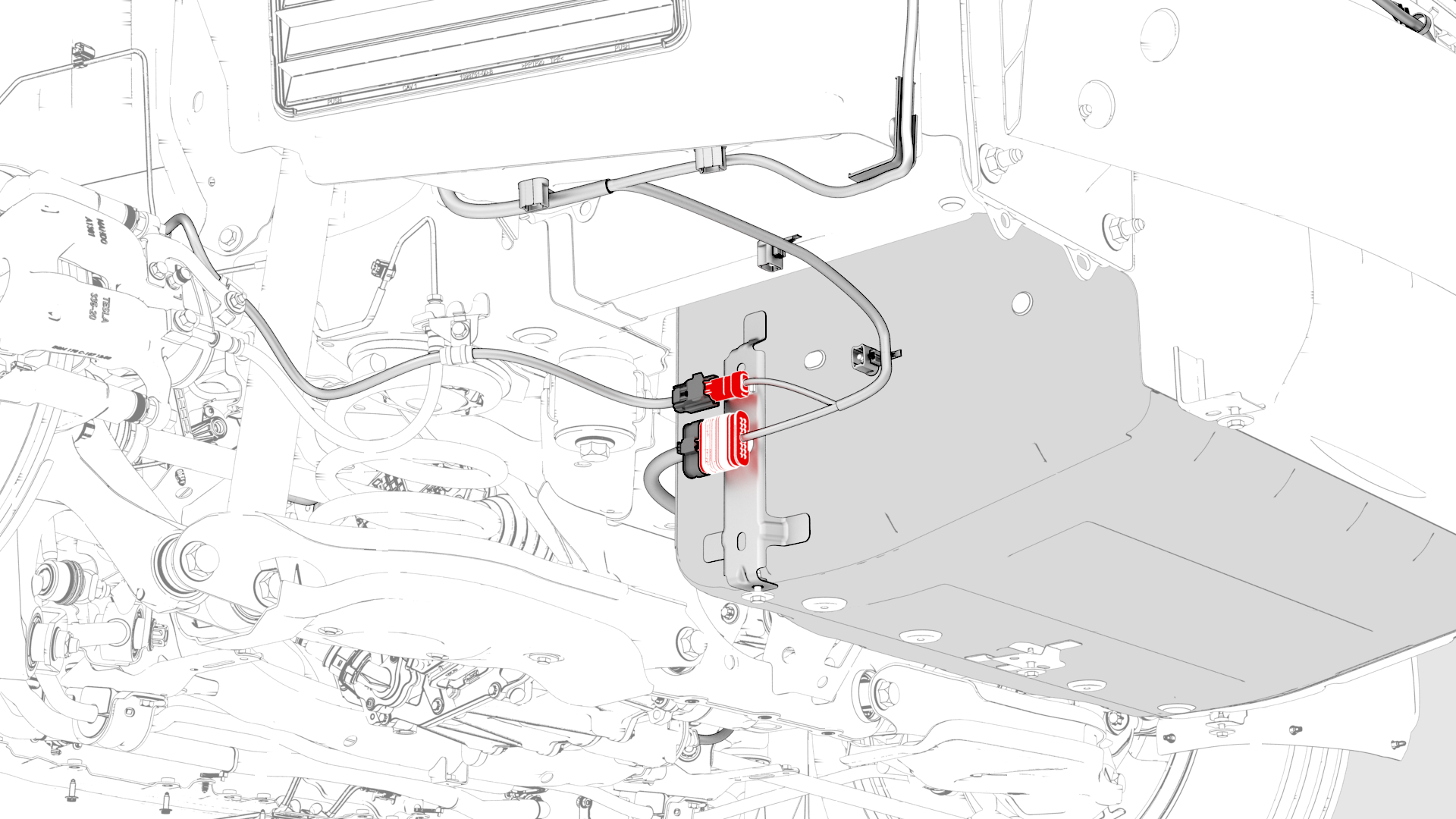
Disconnect the electrical harness from the LH 12V subframe connectors.
-
Remove the LH subframe electrical harness clip from the body.
-
Release the clips that attach the RH inner HV battery return hose to the HV battery.
-
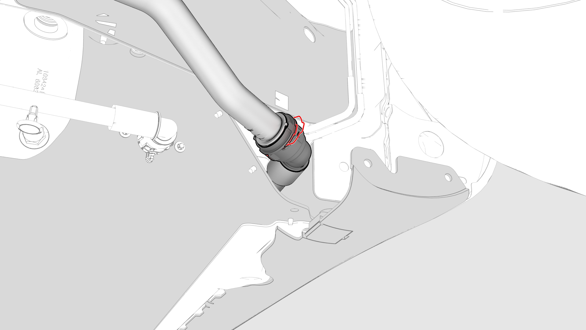
Disconnect the rear drive unit inverter inlet hose from the LH side of the HV battery, and then plug the male and female fittings.
-
Remove the nuts (x2) that attach the HV battery to rear drive unit harness bracket to the HV battery.
-
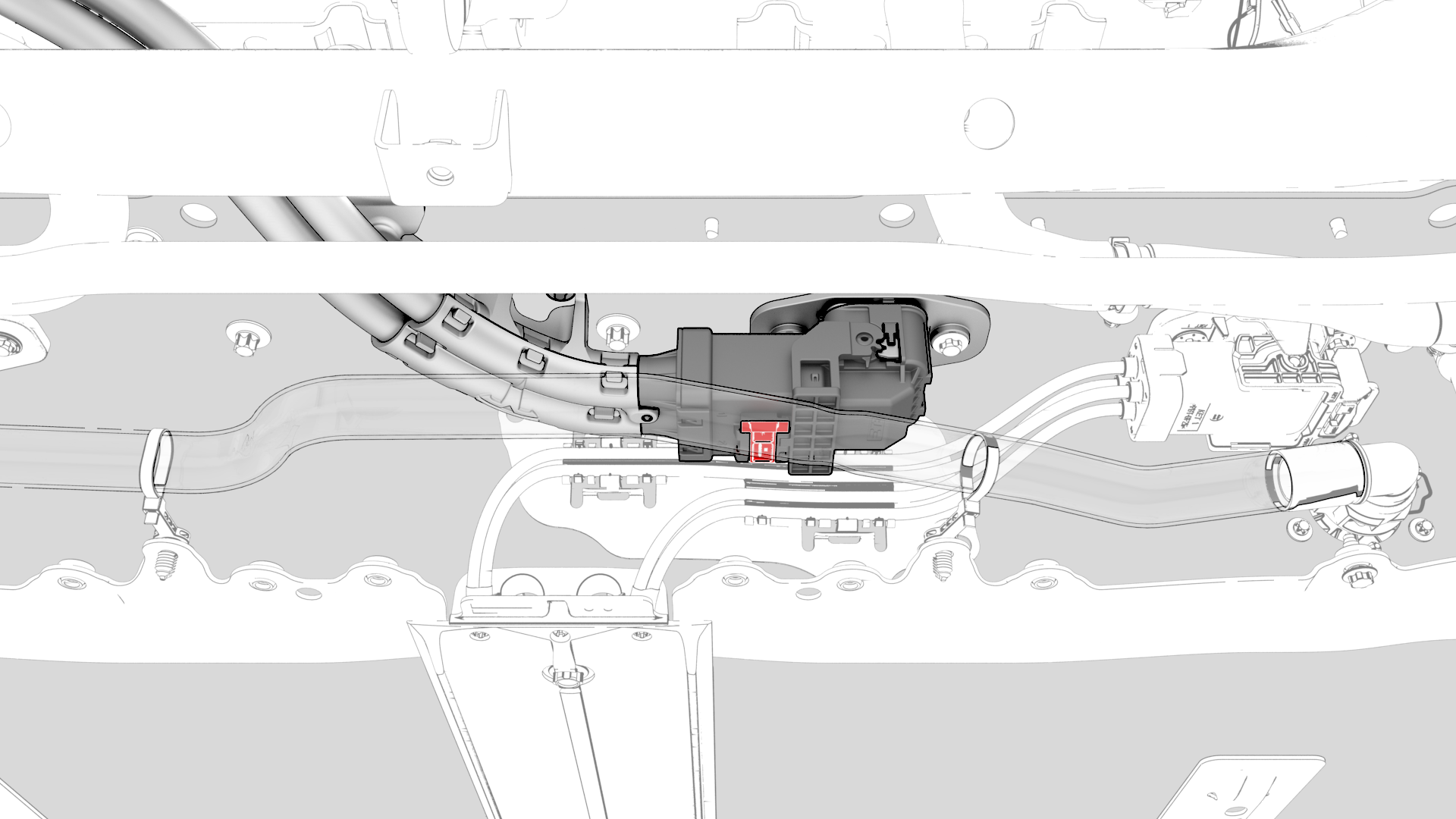
Slide the release to unlock the HV electrical harness connector on the HV battery.
-
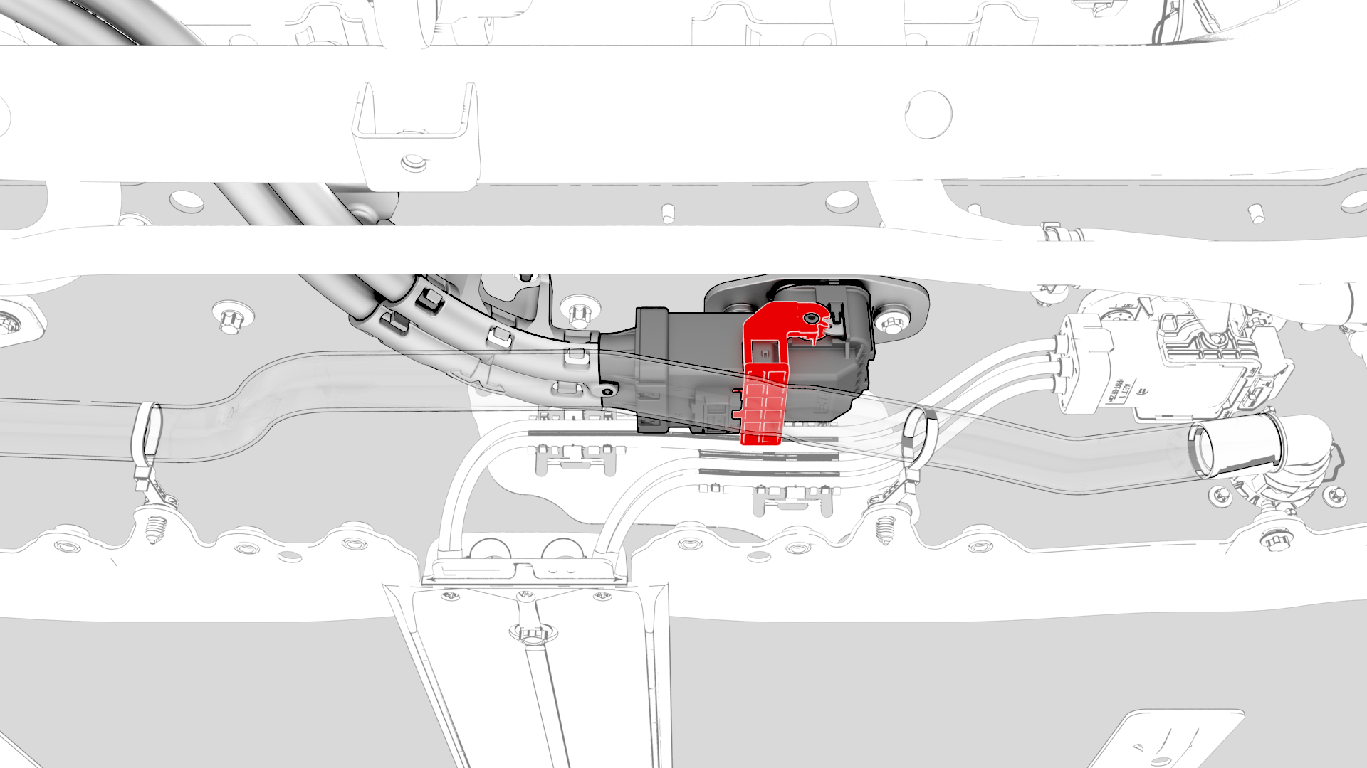
Lift the handle on the HV electrical harness connector, disconnect the harness from the HV battery connector.
-
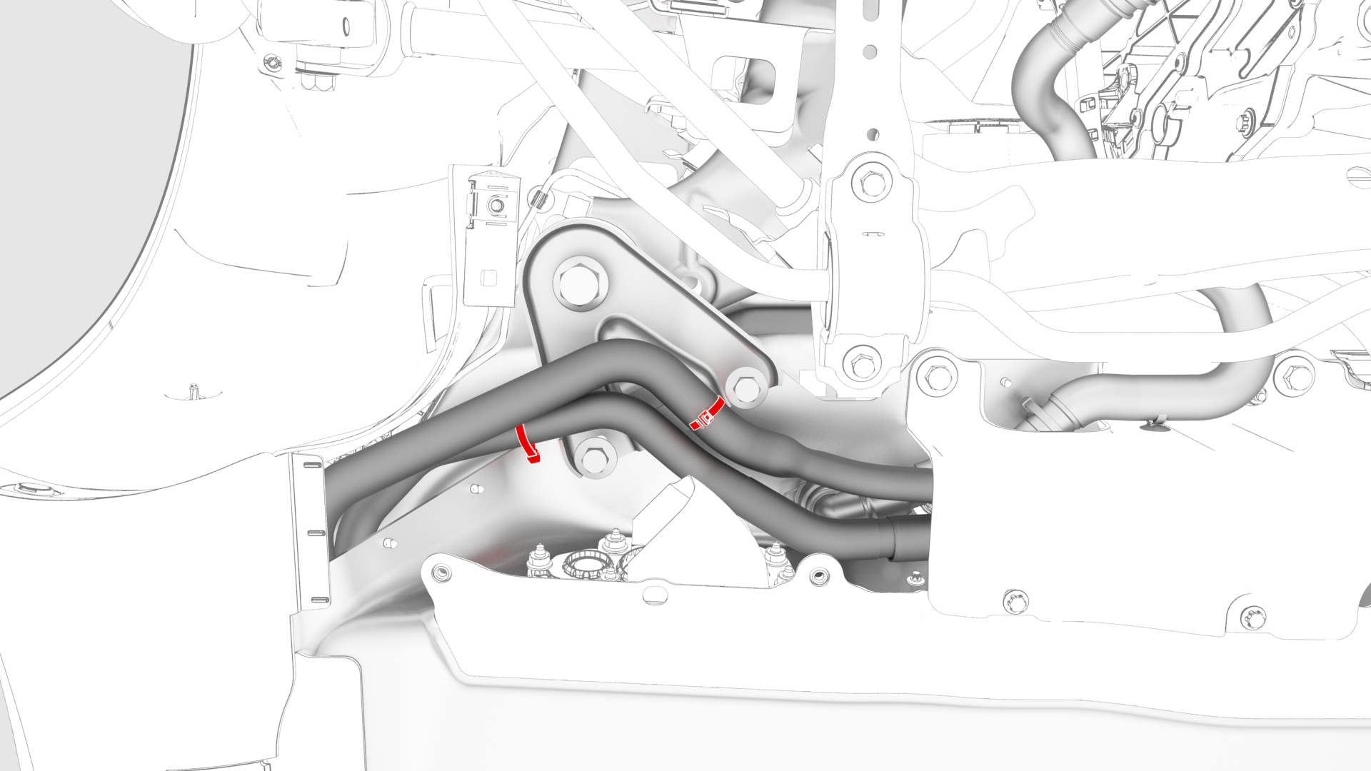
Release the clip, disconnect the rear drive unit outlet hose from the powertrain return hose, and then plug the male and female fittings.
-
Release the fir tree clips that attach the coolant hoses to the LH shear plate.
-
Remove the smaller bolts that attach the LH shear plate to the HV battery.
-
Remove the nut that attaches the rear drive unit ground strap to the body.
-
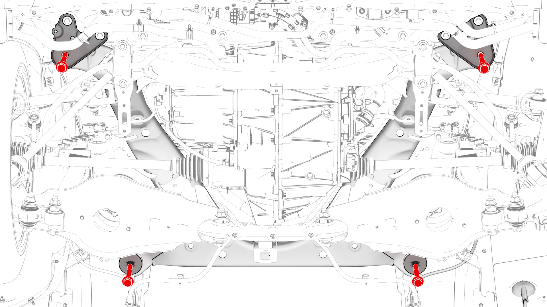
Remove and discard the bolts that attach the shear plates and rear subframe to the body.
Note: When the front bolts are removed, the shear plates are also removed.
-
With an assistant, slowly lower the rear subframe lifting tool to remove the rear subframe from the vehicle.
Caution:Assist with the routing of HV harnesses and coolant hoses through components so that they do not "catch".
-
Move the rear subframe and rear subframe lifting tool away from the vehicle.
| 1 | Use Toolbox to release the rear parking brakes. See Parking Brake - Caliper - Rear - LH (Release). | ||
| 2 | Raise and support the vehicle. See Raise Vehicle - 2 Post Lift. | ||
| 3 | Remove the rear underhood apron. See Underhood Apron - Rear (Remove and Replace). | ||
| 4 | Remove the 2nd row lower seat cushion. See Seat Cushion - Lower - 2nd Row (Remove and Replace). | ||
| 5 | Disconnect 12V power. See 12V Power (Disconnect and Connect). | ||
| 6 | Perform the vehicle electrical isolation procedure. See Vehicle Electrical Isolation Procedure. | ||
| 7 | Remove the HV cap that covers the HV harness located on the LH side of the penthouse. | |
| 8 | Remove the LH 2nd row seat side bolster. See Bolster - Side - Seat - 2nd Row - LH (Remove and Replace). | ||
| 9 | Remove the LH rear sill panel trim. See Trim - Sill Panel - Rear - LH (Remove and Replace). | ||
| 10 | Remove the bolts that attach the wiring harness bracket at the penthouse. | |
| 11 | Release the clips that attach the wiring harness bracket, and then remove the bracket from the vehicle. | ||
| 12 | Release the clip that attaches the wiring harness to the LH lower C-pillar. | |
| 13 | Raise the handle to disconnect the electrical harness from the DC Input assembly. | |
| 14 | Remove the LH and RH rear wheels. See Wheel (Remove and Install). | ||
| 15 | Remove the LH and RH wheel arch liners. See Wheel Arch Liner - Rear - LH (Remove and Replace). | ||
| 16 | Raise the vehicle fully. | ||
| 17 | Remove the front aero shield panel. See Panel - Aero Shield - Front (Remove and Replace). | ||
| 18 | Drain the powertrain coolant. See Powertrain Coolant (Drain and Refill). | ||
| 19 | Remove the mid aero shield panel. See Panel - Aero Shield - Mid (Remove and Replace). | ||
| 20 | Remove the rear fascia diffuser. See Diffuser - Rear Fascia (Remove and Replace). | ||
LH shown, RH similar
| 21 | Disconnect the electrical connector from the LH rear brake caliper. | |
LH shown, RH similar
| 22 | Check the LH rear upper aft link and if present, disconnect the electrical connector from the sensor. | |
LH shown, RH similar
| 23 | If a connector was disconnected in the previous step, release the clip that attaches the connector harness to the underside of the rear subframe. | |
| 24 | Remove the bolts that attach the LH rear brake caliper bracket to the knuckle, and then hang the caliper bracket on the body with an S-hook. | |
| 25 | Remove the bolt that attaches the cover to the LH lower aft link, and then remove the cover from the vehicle. | |
| 26 | Install a spring compressor onto the LH rear coil spring. Caution: Line up the hooks per image and verify that the threaded shaft goes through the body opening when the suspension is compressed.
| |
| 27 | Remove the bolts that attach the LH rear damper at the top mount. | |
| 28 | Disconnect the electrical harness from the LH 12V subframe connectors. | |
| 29 | Remove the LH subframe electrical harness clip from the body. | |
| 30 | Repeat step 21 through step 29 for the RH side of the vehicle. | ||
| 31 | Remove the rear HV battery skid plate. See Skid Plate - HV Battery - Rear (Remove and Replace). | ||
| 32 | Release the clips that attach the RH inner HV battery return hose to the HV battery. | |
| 33 | Position the coolant drain beneath the LH rear of the HV battery. | ||
| 34 | Disconnect the rear drive unit inverter inlet hose from the LH side of the HV battery, and then plug the male and female fittings. | |
| 35 | Release the barrel clip that attaches the rear drive unit inverter inlet hose to the HV battery, and separate the hose from the battery. | ||
| 36 | Remove the nuts (x2) that attach the HV battery to rear drive unit harness bracket to the HV battery. | |
| 37 | Slide the release to unlock the HV electrical harness connector on the HV battery. | |
| 38 | Lift the handle on the HV electrical harness connector, disconnect the harness from the HV battery connector. | |
| 39 | Position the coolant drain beneath the RH rear of the HV battery. | ||
| 40 | Release the clip, disconnect the rear drive unit outlet hose from the powertrain return hose, and then plug the male and female fittings. | |
| 41 | Remove the coolant drain container from underneath the vehicle. | ||
| 42 | Release the fir tree clips that attach the coolant hoses to the LH shear plate. | |
| 43 | Remove the smaller bolts that attach the LH shear plate to the HV battery. | |
| 44 | Repeat step 42 and step 43 for the RH shear plate. | ||
| 45 | Remove the nut that attaches the rear drive unit ground strap to the body. | |
| 46 | Remove the rear stabilizer bar. See Stabilizer Bar - Rear (Remove and Replace). | ||
| 47 | Place the rear subframe lifting tool into position underneath the rear subframe. | ||
| 48 | Attach an air hose to the rear subframe lifting tool. | ||
| 49 | With an assistant, raise the rear subframe lifting tool to support the rear subframe. | ||
| 50 | Loop the straps over the rear subframe, hook the ends of the straps to the metal rings, and then pull the straps tight to restrain the subframe to the rear subframe lifting tool. Note: Lower the vehicle to give more slack to connect the straps to the rings, if necessary.
| ||
| 51 | Remove and discard the bolts that attach the shear plates and rear subframe to the body. Note: When the front bolts are removed, the shear plates are also removed.
| |
| 52 | With an assistant, slowly lower the rear subframe lifting tool to remove the rear subframe from the vehicle. Caution: Assist with the routing of HV harnesses and coolant hoses through components so that they do not "catch".
| ||
| 53 | Disconnect the air supply from the rear subframe lifting tool. | ||
| 54 | Move the rear subframe and rear subframe lifting tool away from the vehicle. |
Install
-
With an assistant, slowly raise the rear drive unit and subframe into position.
Caution:Assist with the routing of HV harnesses and coolant hoses through components so that they are not pinched or broken.
-
Install and hand-tighten the new bolts that attach the shear plates and rear subframe to the body.
Note: Pass the front bolts through the shear plates first, then into the rear subframe, and hand-tighten to the body.
-
Install and hand-tighten the smaller bolts that attach the LH shear plate to the HV battery.
-
Fasten the fir tree clips that attach the coolant hoses to the LH shear plate.
-
Tighten the bolts that attach the rear subframe to the body.
 Torque Rear bolts: 165 NmTorque Front bolts: 128 Nm
 -
Tighten the bolts for the shear plates.Torque 30 Nm
-
Install the ground strap for the rear drive unit.
 Torque 10 Nm
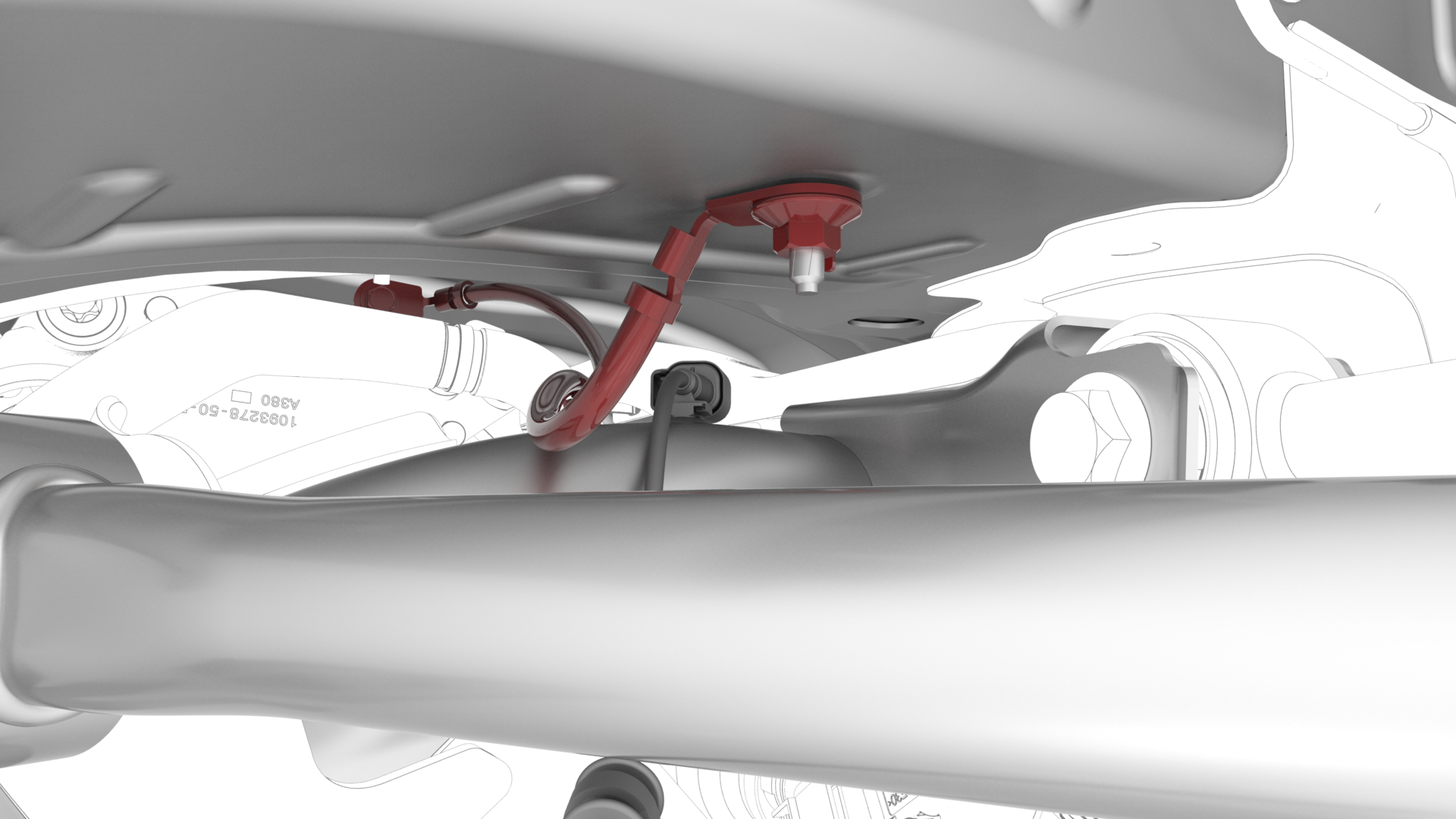 Note: Reinstall the washer if the vehicle had this washer during removal.Note: Make sure that the angle of the ground strap provides enough clearance between the ground strap wire and the ABS wheel speed sensor wiring harness.
 -
Remove the hose plugs, connect the rear drive unit outlet hose to the powertrain return hose, and then fasten the clip.
Caution:Perform a push-pull test to verify that the hose is fully seated.
-
Attach the HV connector lever lock onto the back of the HV electrical harness.
-
Firmly connect the HV electrical harness to the HV battery connector.
Caution:Make sure that the harness fits the connector squarely and tightly.
-
While pressing the harness to the connector, fully lower the handle.
-
Slide the release to lock the HV electrical harness.
-
Install the nuts (x2) that attach the rear drive unit HV electrical harness bracket to the HV battery.Torque 10 Nm
-
Remove the plugs from the male and female fittings, connect the rear drive unit inverter inlet hose to the LH side of the HV battery, and then fasten the clip.
Caution:Perform a push-pull test to verify that the hose is fully seated.
-
Fasten the clips that attach the RH inner HV battery return hose to the HV battery.
-
Fasten the LH subframe electrical harness clip to the body.
-
Connect the electrical connector for the LH of the 12V subframe harness.
LH side shown, RH similar
-
Install the bolts that attach the LH rear damper at the top mount.
 Torque 41 Nm
 -
Remove the spring compressor from the LH rear coil spring.
-
Install the LH rear suspension cover onto the LH lower aft link, and then install the bolt that attaches the cover to the LH lower aft link.
 Torque 6 Nm
 -
Install the LH rear brake caliper bracket onto the knuckle, and then install the bolts that attach the caliper bracket to the knuckle.
 Torque 83 Nm
 -
If previously removed, install the clip that attaches the sensor connector harness to the underside of the rear subframe.
LH shown, RH similar
-
If previously removed, connect the electrical connector to the sensor near the LH rear upper aft link.
LH shown, RH similar
-
Connect the electrical harness to the LH rear brake caliper connector.
| 1 | Position the subframe lifting tool and subframe underneath the vehicle. | ||
| 2 | Connect the air line to the subframe lifting tool. | ||
| 3 | With an assistant, slowly raise the rear drive unit and subframe into position. Caution: Assist with the routing of HV harnesses and coolant hoses through components so that they are not pinched or broken.
| ||
| 4 | Install and hand-tighten the new bolts that attach the shear plates and rear subframe to the body. Note: Pass the front bolts through the shear plates first, then into the rear subframe, and hand-tighten to the body.
| |
| 5 | Install and hand-tighten the smaller bolts that attach the LH shear plate to the HV battery. | |
| 6 | Fasten the fir tree clips that attach the coolant hoses to the LH shear plate. | |
| 7 | Repeat step 5 and step 6 for the RH shear plate. | ||
| 8 | Tighten the bolts that attach the rear subframe to the body. Torque Rear bolts: 165 Nm Torque Front bolts: 128 Nm | ||
| 9 | Tighten the bolts for the shear plates. Torque 30 Nm | ||
| 10 | Release the straps and lower the subframe lifting tool from the vehicle. | ||
| 11 | Disconnect the air line from the subframe lifting tool, and then remove the tool from underneath the vehicle. | ||
| 12 | Install the rear stabilizer bar. See Stabilizer Bar - Rear (Remove and Replace). | ||
| 13 | Install the ground strap for the rear drive unit. Torque 10 Nm Note: Reinstall the washer if the vehicle had this washer during removal.
Note: Make sure that the angle of the ground strap provides enough clearance between the ground strap wire and the ABS wheel speed sensor wiring harness.
| |
| 14 | Position the coolant drain beneath the RH rear of the HV battery. | ||
| 15 | Remove the hose plugs, connect the rear drive unit outlet hose to the powertrain return hose, and then fasten the clip. Caution: Perform a push-pull test to verify that the hose is fully seated.
| |
| 16 | Fully raise the handle on the rear drive unit HV electrical harness. | ||
| 17 | Attach the HV connector lever lock onto the back of the HV electrical harness. | |
| 18 | Firmly connect the HV electrical harness to the HV battery connector. Caution: Make sure that the harness fits the connector squarely and tightly.
| ||
| 19 | While pressing the harness to the connector, remove the HV connector lever lock. | ||
| 20 | While pressing the harness to the connector, fully lower the handle. | |
| 21 | Slide the release to lock the HV electrical harness. | |
| 22 | Install the nuts (x2) that attach the rear drive unit HV electrical harness bracket to the HV battery. Torque 10 Nm | |
| 23 | Position the coolant drain beneath the LH rear of the HV battery. | ||
| 24 | Remove the plugs from the male and female fittings, connect the rear drive unit inverter inlet hose to the LH side of the HV battery, and then fasten the clip. Caution: Perform a push-pull test to verify that the hose is fully seated.
| |
| 25 | Fasten the barrel clip that attaches the rear drive unit inverter inlet hose to the HV battery. | ||
| 26 | Fasten the clips that attach the RH inner HV battery return hose to the HV battery. | |
| 27 | Remove the coolant drain container from underneath the vehicle. | ||
| 28 | Install the rear HV battery skid plate. See Skid Plate - HV Battery - Rear (Remove and Replace). | ||
| 29 | Fasten the LH subframe electrical harness clip to the body. | |
LH side shown, RH similar
| 30 | Connect the electrical connector for the LH of the 12V subframe harness. | |
| 31 | Install the bolts that attach the LH rear damper at the top mount. Torque 41 Nm | |
| 32 | Check the torque for any LH suspension bolts that were loosened while the rear subframe assembly was removed from the vehicle. See Suspension - Rear (Check Torque). | ||
| 33 | Remove the spring compressor from the LH rear coil spring. | |
| 34 | Install the LH rear suspension cover onto the LH lower aft link, and then install the bolt that attaches the cover to the LH lower aft link. Torque 6 Nm | |
| 35 | Install the LH rear brake caliper bracket onto the knuckle, and then install the bolts that attach the caliper bracket to the knuckle. Torque 83 Nm | |
LH shown, RH similar
| 36 | If previously removed, install the clip that attaches the sensor connector harness to the underside of the rear subframe. | |
LH shown, RH similar
| 37 | If previously removed, connect the electrical connector to the sensor near the LH rear upper aft link. | |
| 38 | Connect the electrical harness to the LH rear brake caliper connector. | |
| 39 | Repeat step 29 through step 38 for the RH side of the vehicle. | ||
| 40 | Install the rear fascia diffuser. See Diffuser - Rear Fascia (Remove and Replace). | ||
| 41 | Install the LH and RH wheel arch liners. See Wheel Arch Liner - Rear - LH (Remove and Replace). | ||
| 42 | Install the LH and RH rear wheels. See Wheel (Remove and Install). | ||
| 43 | Perform the penthouse air leak test. See Penthouse Air Leak Test. | ||
| 44 | Connect 12V power. See 12V Power (Disconnect and Connect). | ||
| 45 | Perform a vacuum refill of the cooling system. See Cooling System (Vacuum Refill). | ||
| 46 | Perform a four wheel alignment check and adjustment. See Four Wheel Alignment (Check and Adjust).
|