Inverter - Rear Drive Unit (Remove and Install)
Correction code 4020060140200601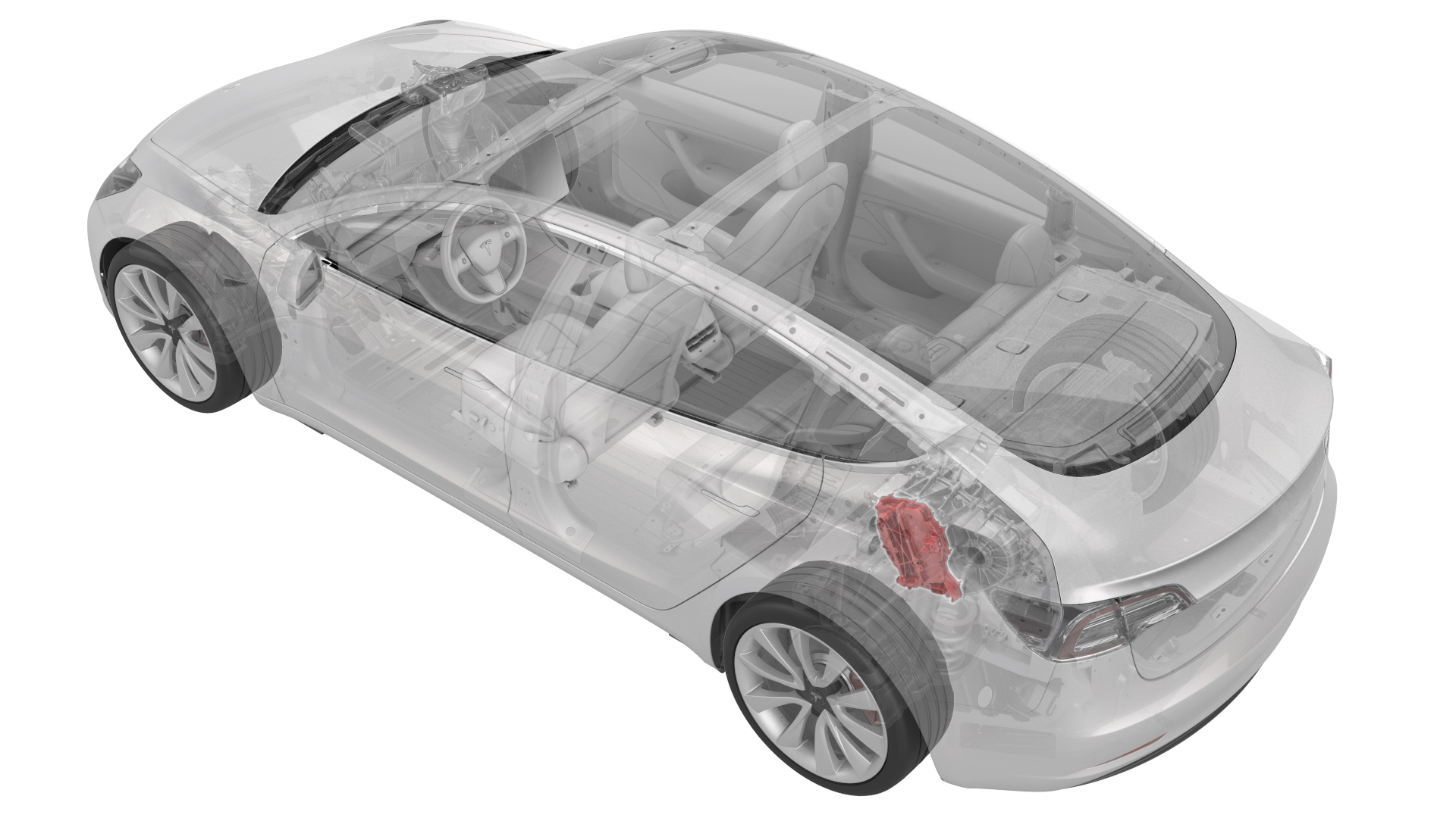
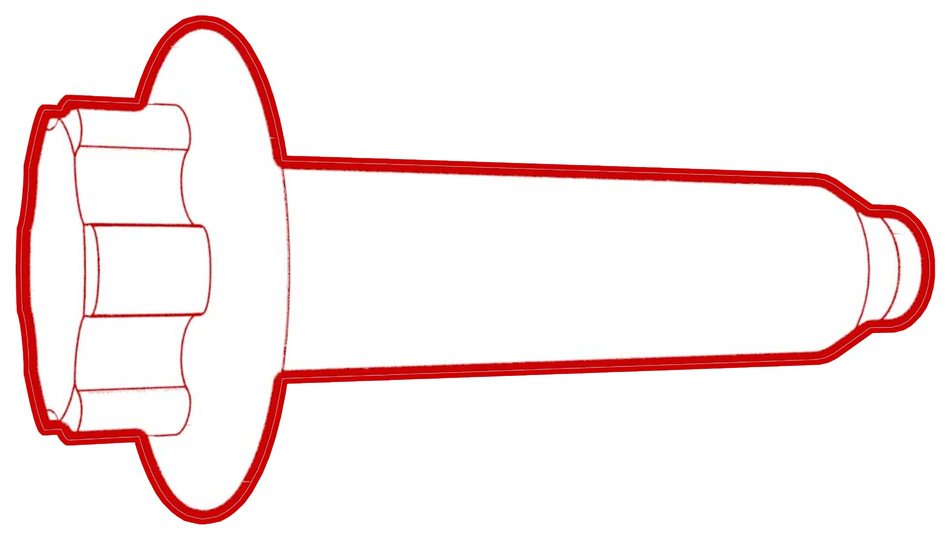
- 1130479-00-A Skt, 3/8in Dr, 10EP Torx Plus External
SPECIAL TOOLS
Skt, 3/8in Dr, 10EP Torx Plus External (1130479-00-A) |

Caution:
This procedure must not be used for replacement of a defective inverter. For inverter replacement, see Inverter - Rear Drive Unit (Remove and Replace). Use this procedure to remove and install a functional inverter as part of another component's service operation. For example, the rear drive unit motor or gearbox.
Remove
-
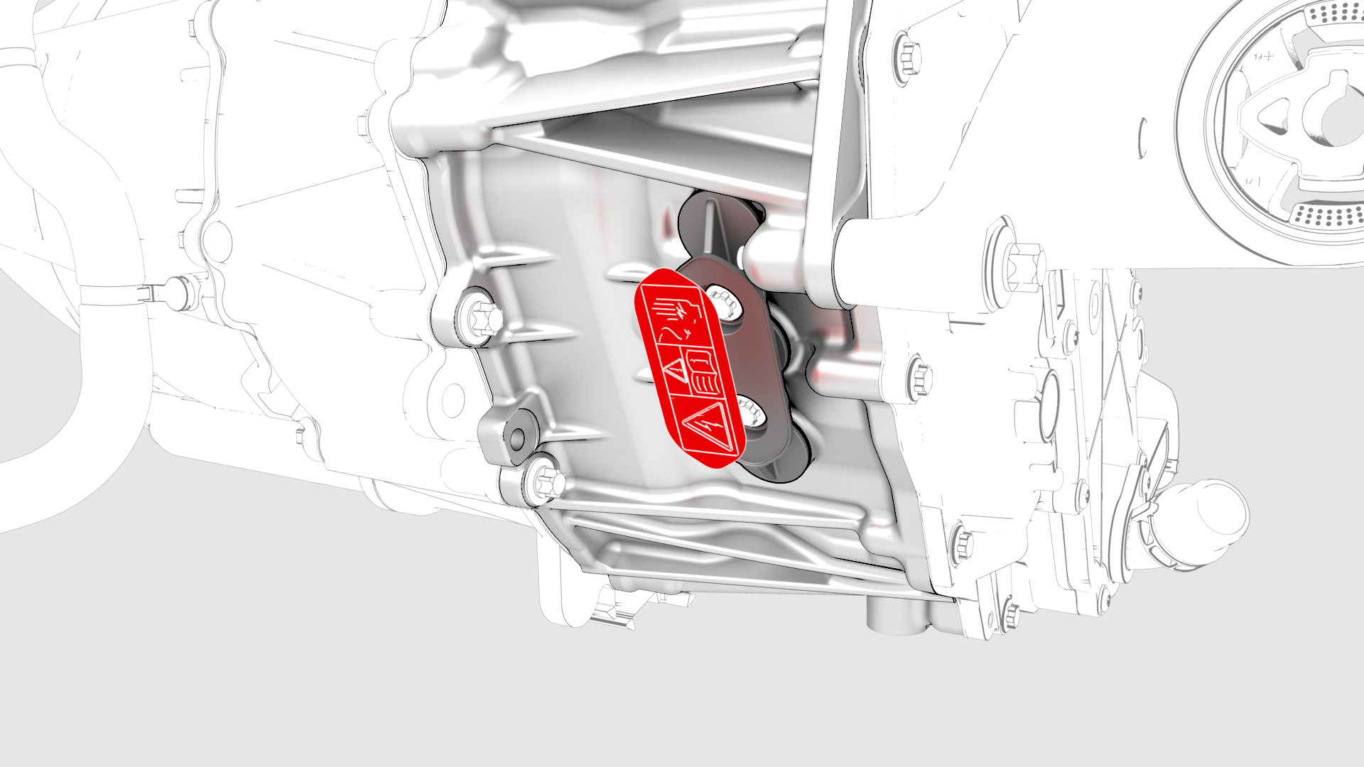
Remove the 3-phase access label.
-
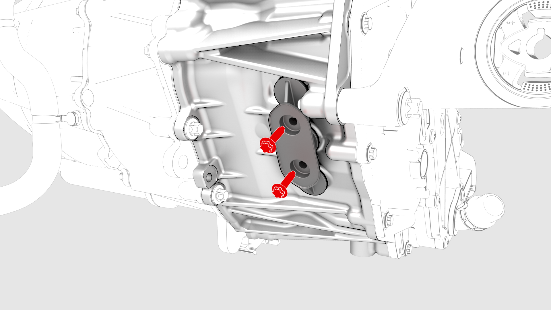
Remove the bolts (x2) that attach the 3-phase access cover to the rear drive unit.
-
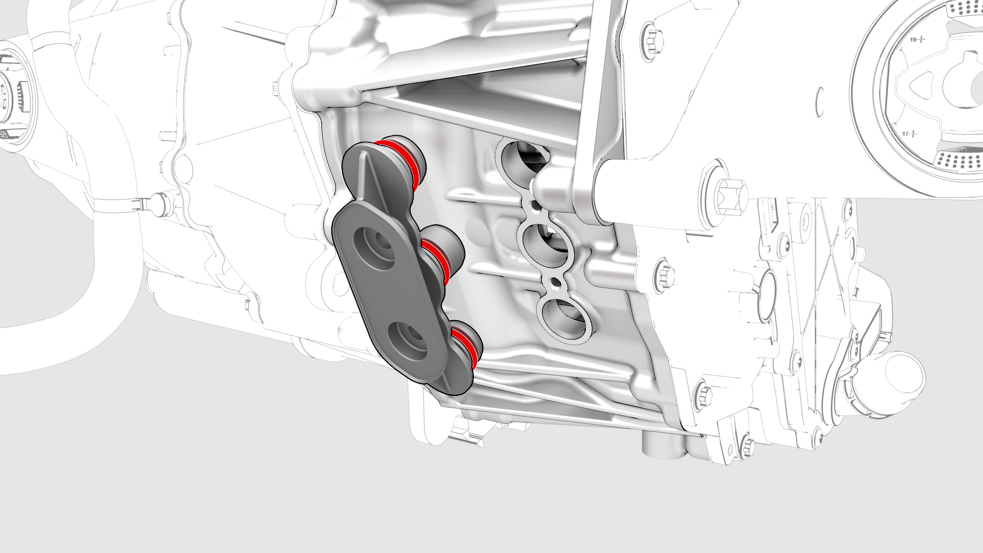
Remove and discard the 3-phase access cover.
-
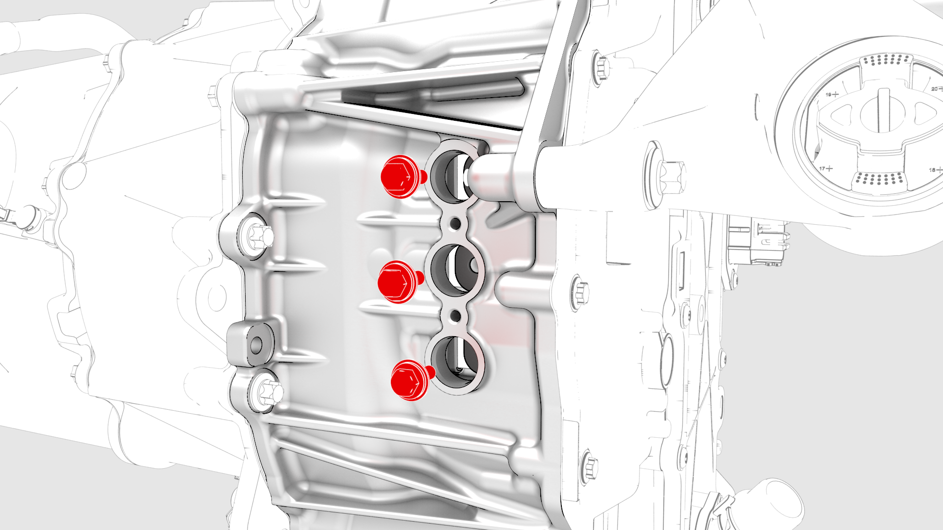
Remove and discard the bolts (x3) that attach the 3-phase terminals to the inverter assembly.
-
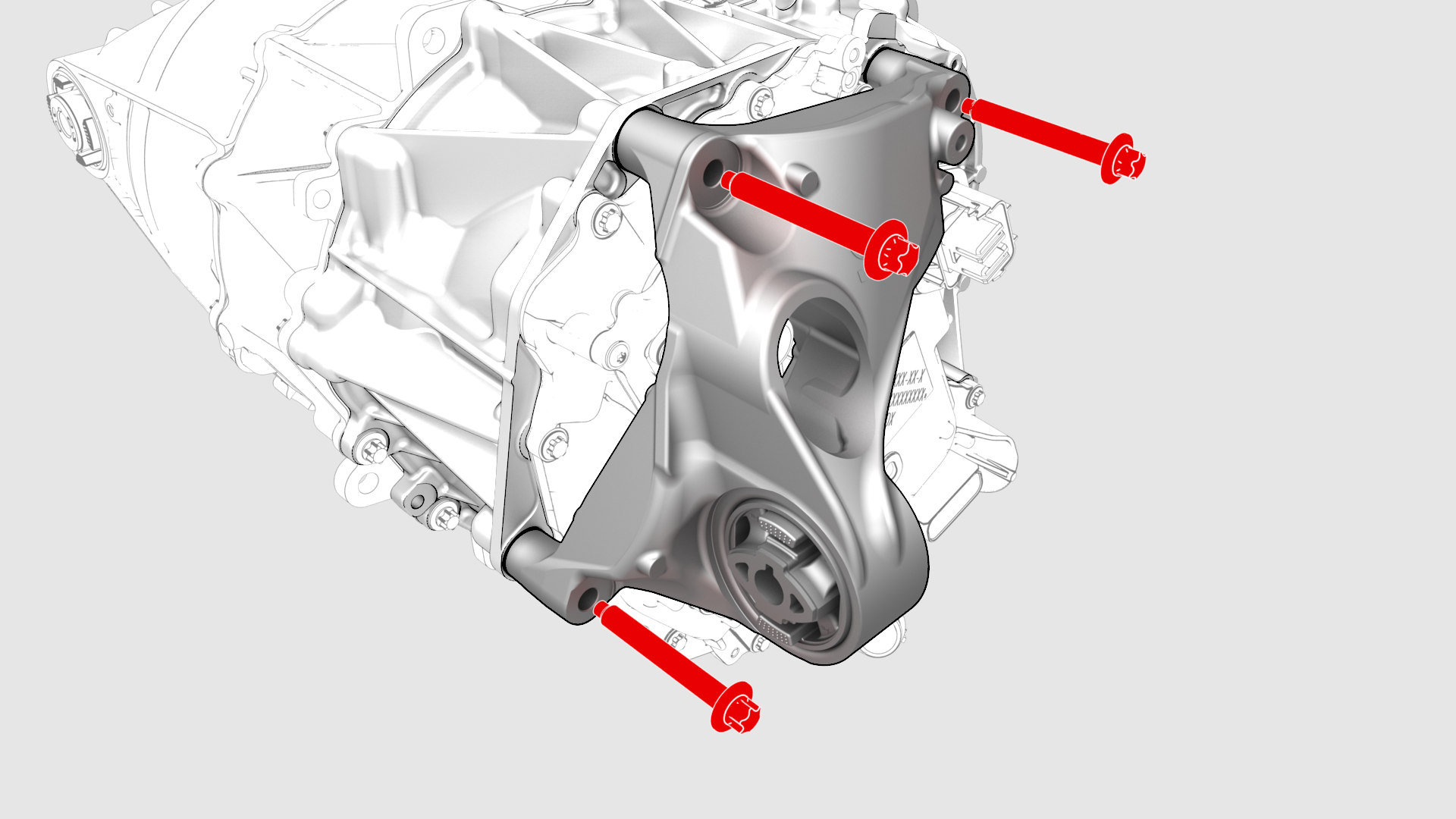
Remove the bolts that attach the LH mount to the rear drive unit, and remove the mount from the rear drive unit.
-
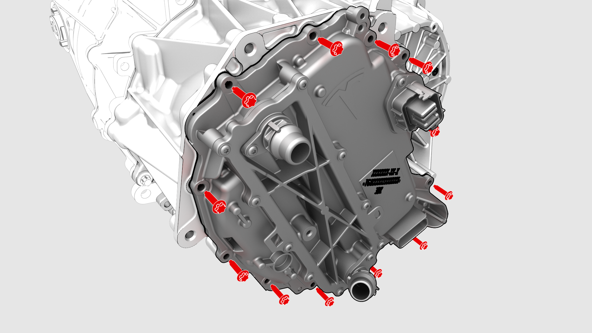
Remove and discard the bolts (x12) that attach the inverter to the gearbox assembly.
-
Carefully remove the inverter assembly from the rear drive unit and allow the coolant to drain.
| 1 | Remove the rear drive unit. See Drive Unit - Rear (Remove and Replace). |
| 2 | Secure an ESD strap to the inverter housing. |
| 3 | Remove the 3-phase access label. |
| 4 | Remove the bolts (x2) that attach the 3-phase access cover to the rear drive unit. |
| 5 | Remove and discard the 3-phase access cover. |
| 6 | Remove and discard the bolts (x3) that attach the 3-phase terminals to the inverter assembly. |
| 7 | Remove the bolts that attach the LH mount to the rear drive unit, and remove the mount from the rear drive unit. |
| 8 | Remove and discard the bolts (x12) that attach the inverter to the gearbox assembly. |
| 9 | Carefully remove the inverter assembly from the rear drive unit and allow the coolant to drain. |
| 10 | Remove and discard the inverter gasket. |
Install
-
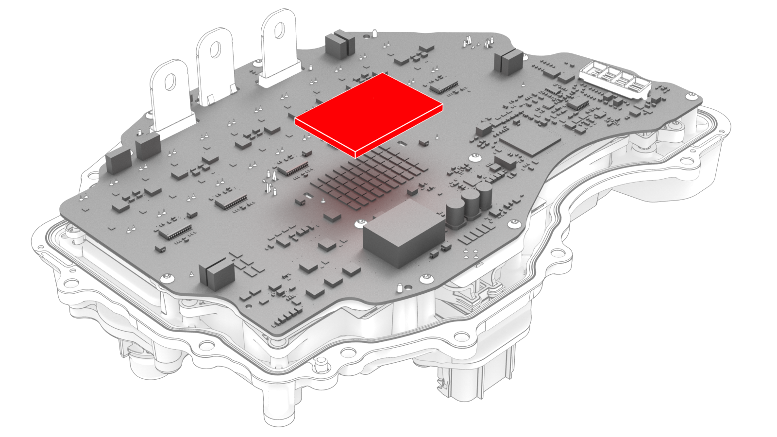
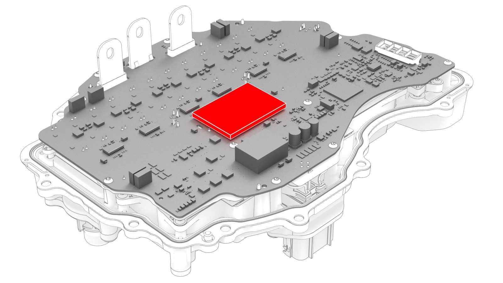
Carefully peel the gap pad from the inverter PCB.
-
Peel the backing off of the new gap pad, position the pad into place, and press it onto the inverter PCB.
-
Carefully align the inverter to the 2 pins in the rear drive unit, and then install the inverter to the rear drive unit. Make sure that the 3-phase terminals align during installation.
Caution:Avoid damage to the printed circuit board of the inverter.
-
Hand-tighten the new bolts (x12) that attach the inverter to the gearbox assembly.
-
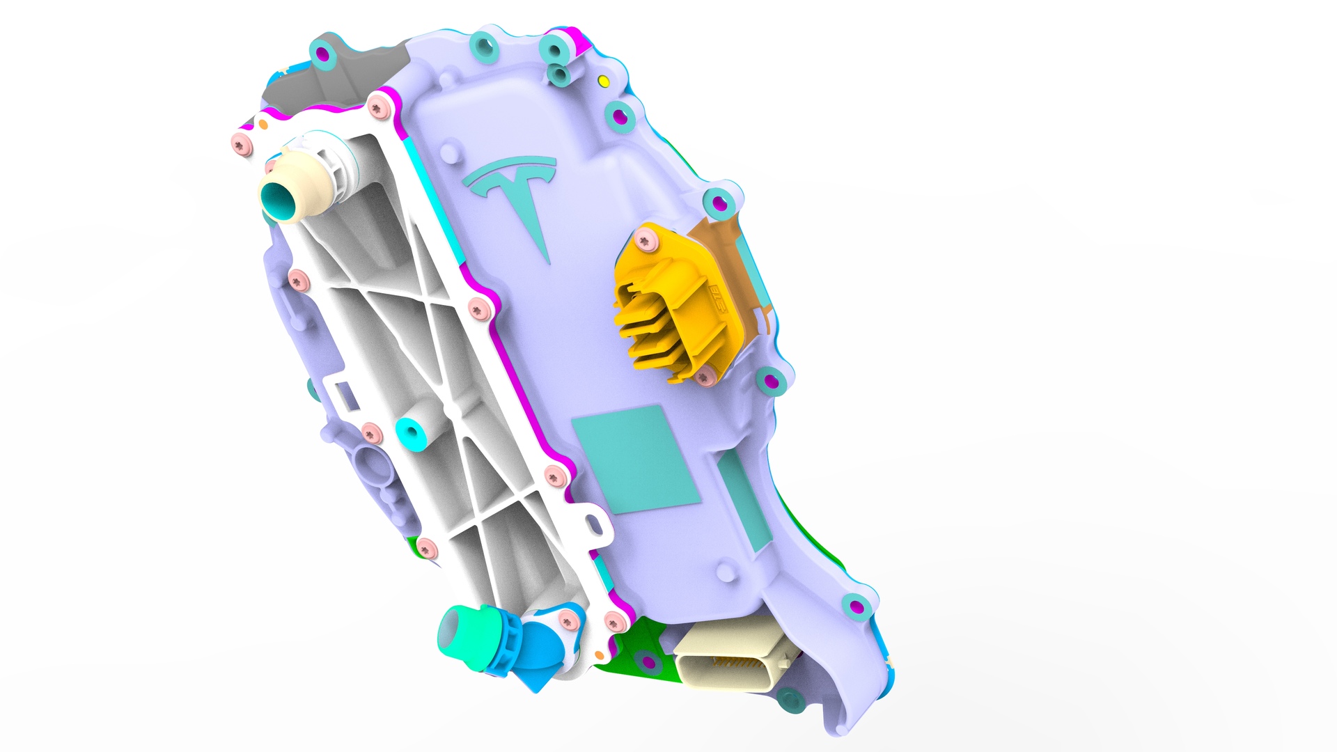
Torque the bolts in the sequence shown.
 Torque 5 Nm +20 deg
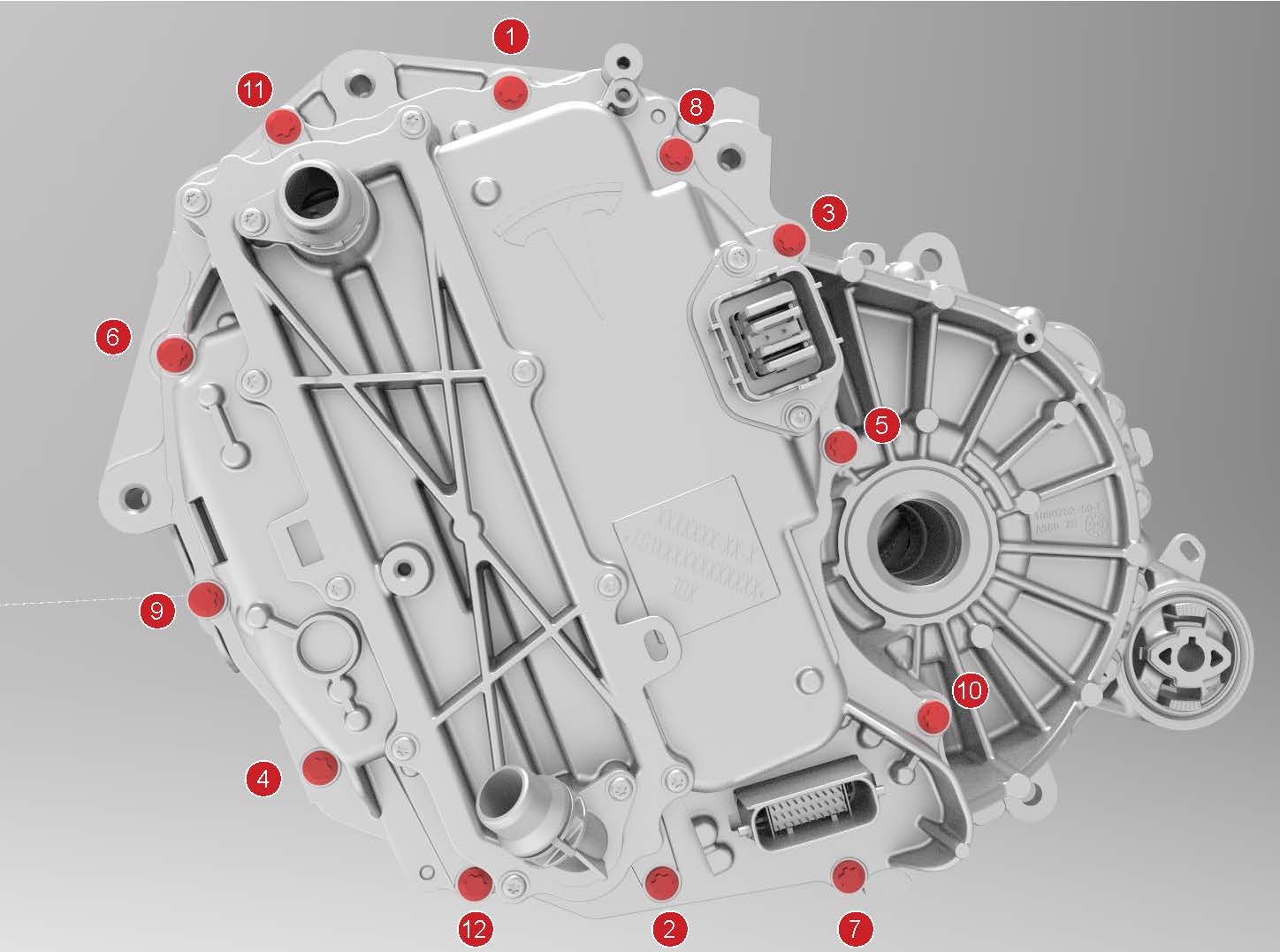
-
Install the LH rear drive unit mount to the rear drive unit, and then hand-tighten the bolts (x3) that attach the mount to the rear drive unit.
-
Tighten the bolts in a two-step, counter-clockwise pattern, starting with the upper-right bolt.
 Torque 35 Nm +55 deg
 -
Install the new bolts (x3) that attach the 3 phase cable to the inverter assembly.
-
Tighten the bolts to this specification.
 Torque 11.5 Nm
 - Loosen the bolts 180 degrees.
-
Tighten the bolts to this specification.
 Torque 5 Nm +40 deg
-
Tighten the bolts to this specification.
-
Apply a film of ATF-9 fluid to the walls of the gear case bores, and then install the new 3-phase access cover.
-
Install the bolts (x2) that attach the 3-phase access cover to the rear drive unit assembly.
 Torque 7.5 Nm
 -
Apply a new 3-phase access label.
| 1 | Secure the ESD strap to the inverter housing. | ||
| 2 | Carefully peel the gap pad from the inverter PCB. | |
| 3 | Use an IPA wipe to remove any residue and prepare the gap pad location on the inverter PCB. | ||
| 4 | Peel the backing off of the new gap pad, position the pad into place, and press it onto the inverter PCB. | |
| 5 | Inspect the condition of the gap pad on the inverter PCB.
| ||
| 6 | Install a new inverter gasket. | ||
| 7 | Use an IPA wipe to clean the HV mating surfaces of the motor and inverter 3-phase terminals. | ||
| 8 | Carefully align the inverter to the 2 pins in the rear drive unit, and then install the inverter to the rear drive unit. Make sure that the 3-phase terminals align during installation. Caution: Avoid damage to the printed circuit board of the inverter.
| ||
| 9 | Hand-tighten the new bolts (x12) that attach the inverter to the gearbox assembly. | |
| 10 | Torque the bolts in the sequence shown. Torque 5 Nm +20 deg | |
| 11 | Install the LH rear drive unit mount to the rear drive unit, and then hand-tighten the bolts (x3) that attach the mount to the rear drive unit. | |
| 12 | Tighten the bolts in a two-step, counter-clockwise pattern, starting with the upper-right bolt. Torque 35 Nm +55 deg | ||
| 13 | Install the new bolts (x3) that attach the 3 phase cable to the inverter assembly.
| |
| 14 | Apply a film of ATF-9 fluid to the walls of the gear case bores, and then install the new 3-phase access cover. | |
| 15 | Install the bolts (x2) that attach the 3-phase access cover to the rear drive unit assembly. Torque 7.5 Nm | |
| 16 | Perform an inverter air leak test. See Inverter Air Leak Test. | ||
| 17 | Apply a new 3-phase access label. | |
| 18 | Remove the ESD wrist strap. | ||
| 19 | Install the rear drive unit. See Drive Unit - Rear (Remove and Replace). |