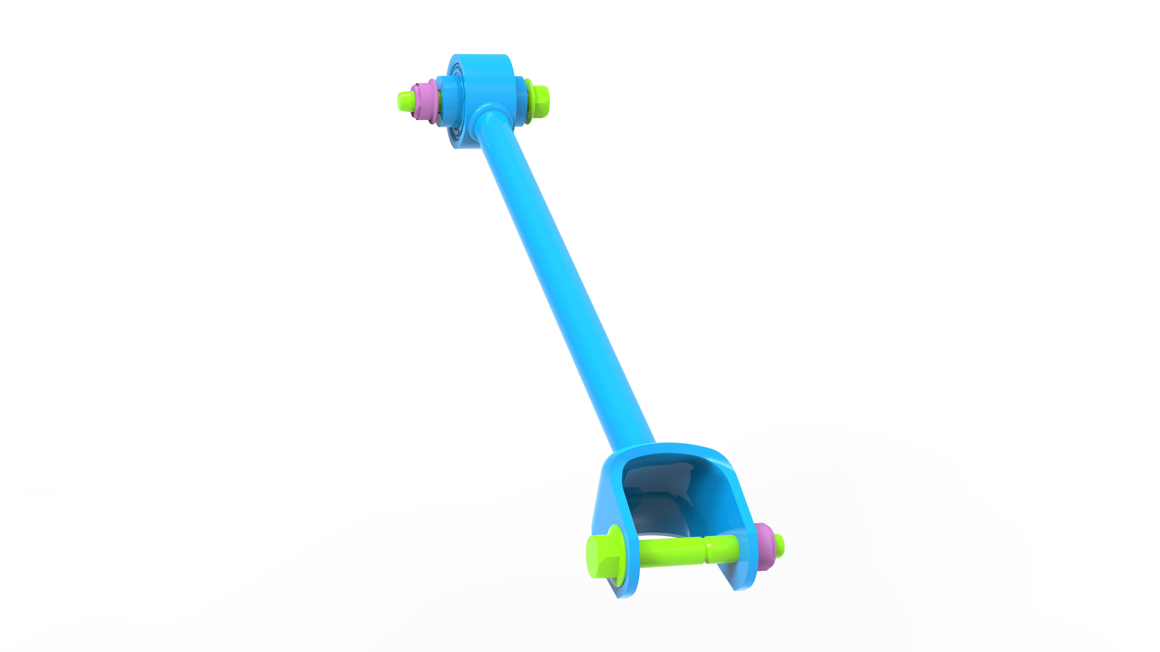
Link - Fore - Lower - Rear - LH (Remove and Replace)
Correction code 3103200131032001
- 1135103-00-ATool, Spring Compressor, Hook, Model 3
SPECIAL TOOLS
Tool, Spring Compressor, Hook, Model 3 (1135103-00-A) |
Remove
-
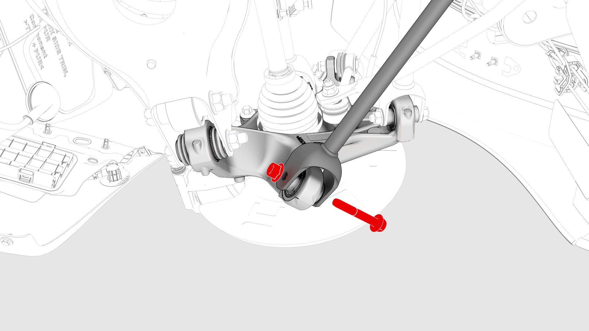
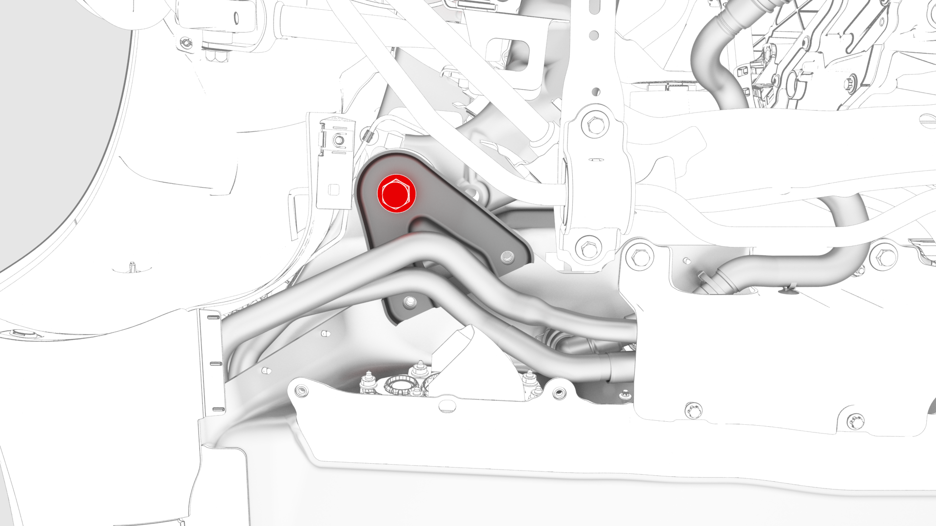
Remove the bolt and nut that attach the LH rear lower fore link to the knuckle.
-
Remove the clips that attach the coolant hose to the LH shear plate.
-
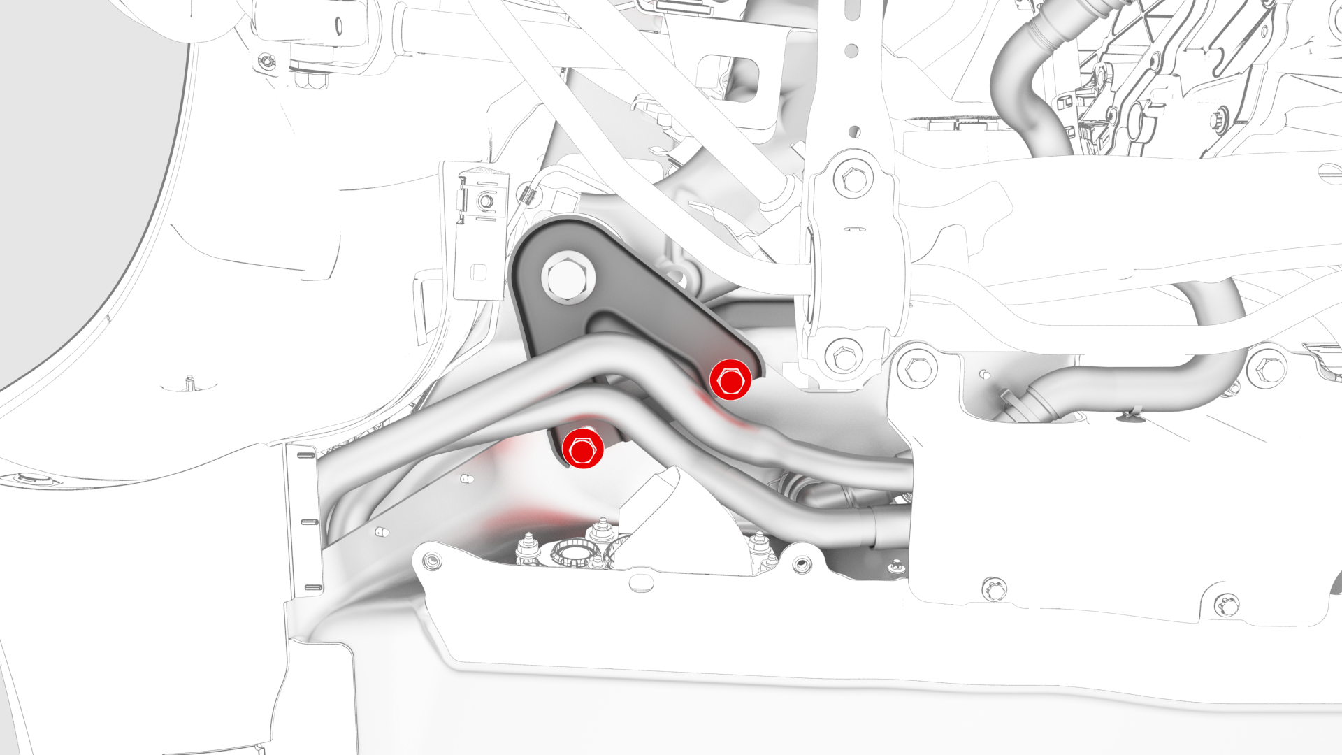
Remove the smaller bolts that attach the LH shear plate to the HV battery.
-
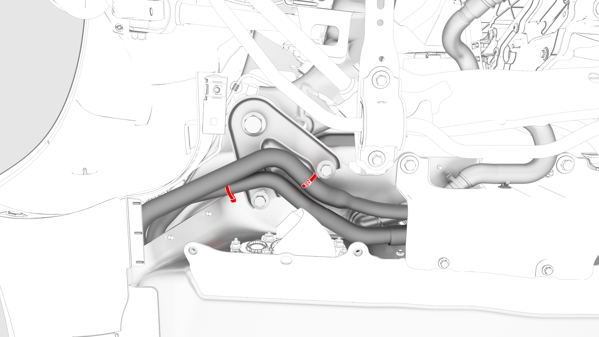
Loosen the large bolt that attaches the LH shear plate and subframe to the body, and then rotate the shear plate aside.
-
Remove the bolt that attaches the LH rear lower fore link to the subframe.

-
Remove the LH rear lower fore link from the vehicle.
| 1 | Raise and support the vehicle. See Raise Vehicle - 2 Post Lift. | ||
| 2 | Remove the LH rear wheel. See Wheel (Remove and Install). | ||
| 3 | Remove the LH rear wheel arch liner. See Wheel Arch Liner - Rear - LH (Remove and Replace). | ||
| 4 | Remove the mid aero shield panel. See Panel - Aero Shield - Mid (Remove and Replace). | ||
| 5 | Place support stand underneath the middle of the rear subframe. | ||
| 6 | Remove the bolt and nut that attach the LH rear lower fore link to the knuckle. | |
| 7 | Remove the clips that attach the coolant hose to the LH shear plate. | |
| 8 | Remove the smaller bolts that attach the LH shear plate to the HV battery. | |
| 9 | Loosen the large bolt that attaches the LH shear plate and subframe to the body, and then rotate the shear plate aside. | |
| 10 | Remove the bolt that attaches the LH rear lower fore link to the subframe. | |
| 11 | Remove the LH rear lower fore link from the vehicle. |
Install
-
Install the LH rear lower fore link to the subframe, and then hand-tighten the bolt that attaches the LH rear lower fore link to the subframe.
-
Hand-tighten the bolt and the nut that attaches the LH rear lower fore link to the knuckle.
-
Hand-tighten the smaller bolts that attach the LH shear plate to the HV battery.
-
Install the bolt that attaches the larger LH shear plate and subframe to the body.
 Torque 165 Nm
 -
Tighten the bolts (x2) that attach the smaller LH shear plate to the HV battery.
 Torque 30 Nm
 -
Install the clips that attach the coolant hose to the LH shear plate.
-
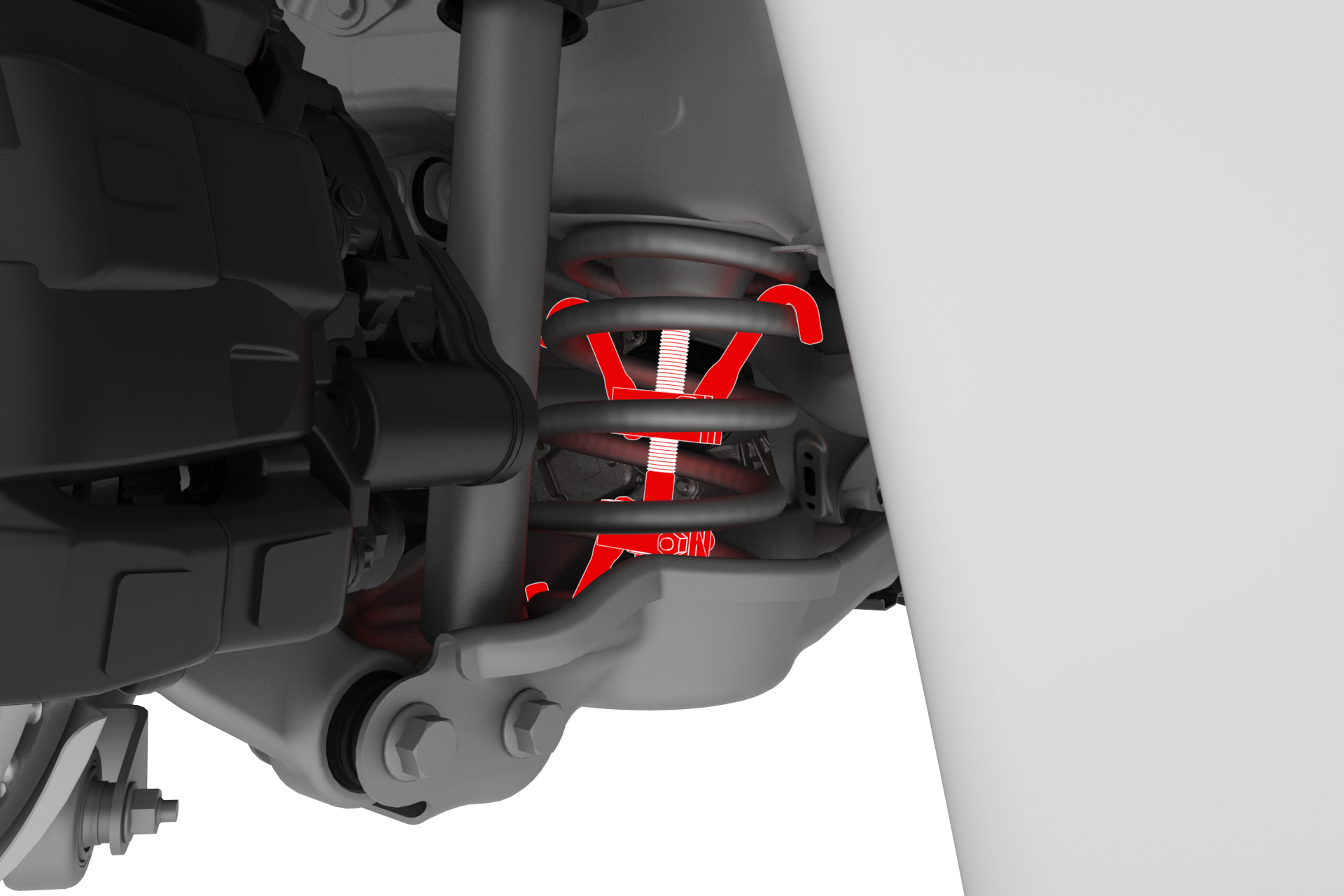
Install a spring compressor onto the LH rear coil spring. Line up the hooks per image and verify that the spindle goes through the body opening when the suspension is compressed.
-
Position a support stand underneath the LH rear suspension, and then raise the support stand to simulate vehicle at ride height.
 Note: Make sure that the support stand does not block access to the spring compressor or suspension bolts.Note: Use the rear ride height torque gauge to verify that the rear suspension is set to ride height specifications and adjust the support stand or spring compressor tool , if necessary.
 -
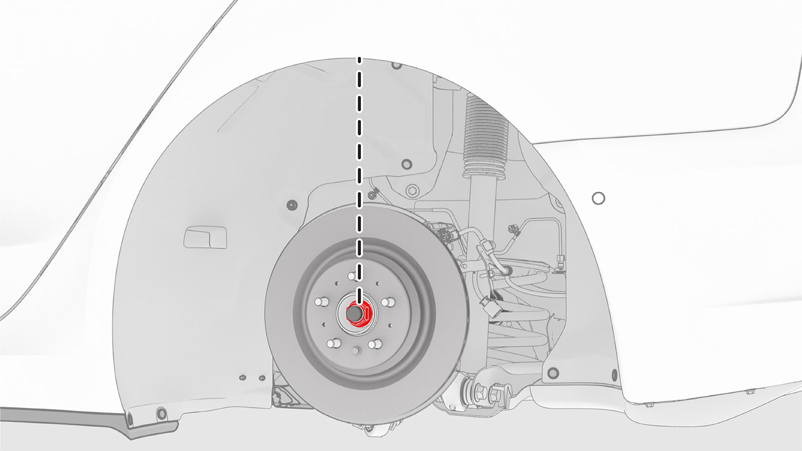
Measure the distance between the bottom of the quarter panel to the center of the rear axle to make sure that the rear suspension is set to ride height: The distance should measure 378 mm.
-
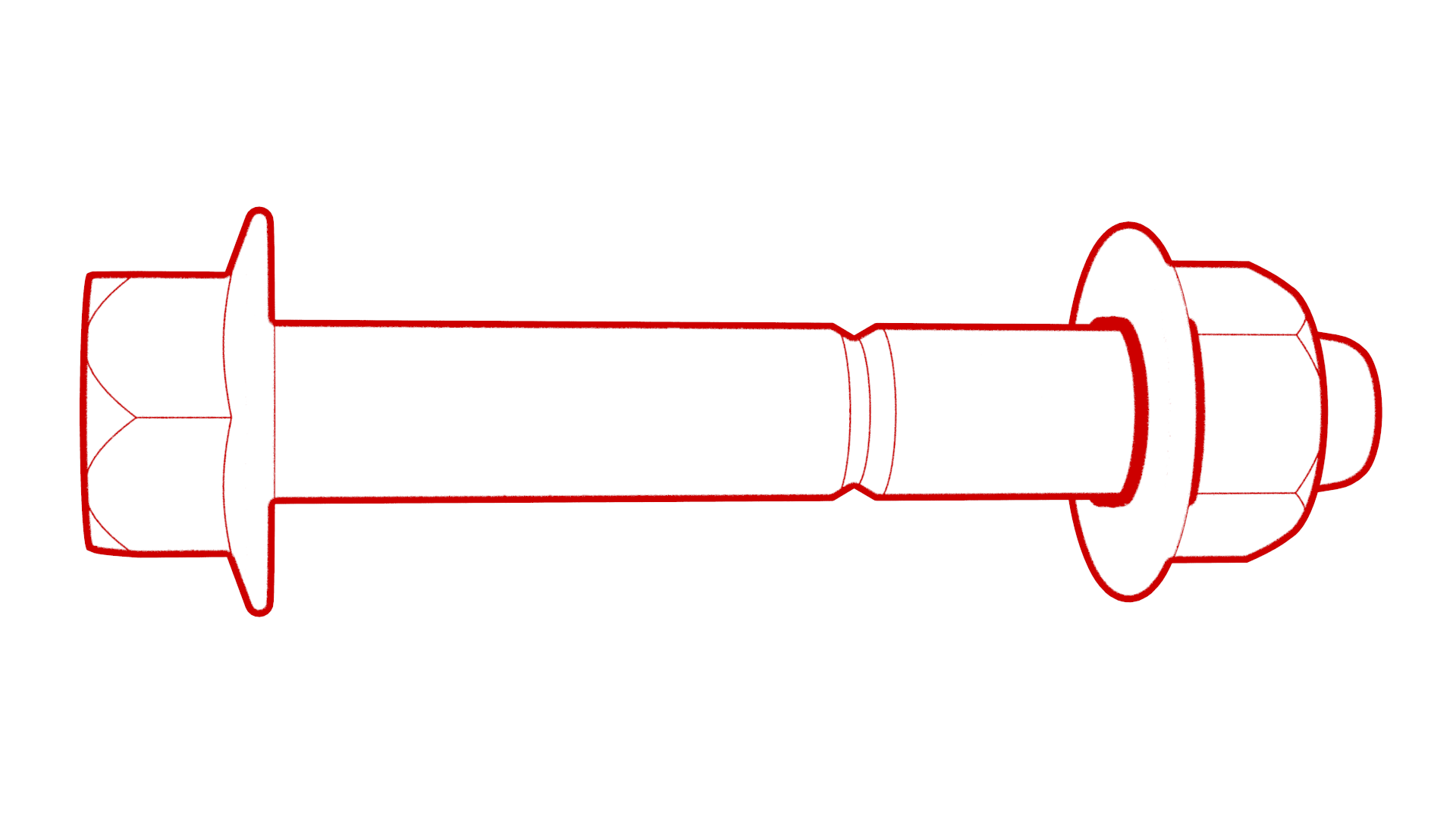
Tighten the bolts that attach the LH rear lower fore link bolt to the knuckle and to the subframe. Mark the bolt with a paint pen.
 Torque 76 Nm
| 1 | Install the LH rear lower fore link to the subframe, and then hand-tighten the bolt that attaches the LH rear lower fore link to the subframe. | |
| 2 | Hand-tighten the bolt and the nut that attaches the LH rear lower fore link to the knuckle. | |
| 3 | Hand-tighten the smaller bolts that attach the LH shear plate to the HV battery. | |
| 4 | Install the bolt that attaches the larger LH shear plate and subframe to the body. Torque 165 Nm | |
| 5 | Tighten the bolts (x2) that attach the smaller LH shear plate to the HV battery. Torque 30 Nm | |
| 6 | Install the clips that attach the coolant hose to the LH shear plate. | |
| 7 | Remove the support stand from underneath the vehicle. | ||
| 8 | Install a spring compressor onto the LH rear coil spring. Line up the hooks per image and verify that the spindle goes through the body opening when the suspension is compressed. | |
| 9 | Position a support stand underneath the LH rear suspension, and then raise the support stand to simulate vehicle at ride height. Note: Make sure that the support stand does not block access to the spring compressor or suspension bolts.
Note: Use the rear ride height torque gauge to verify that the rear suspension is set to ride height specifications and adjust the support stand or spring compressor tool , if necessary.
| |
| 10 | Measure the distance between the bottom of the quarter panel to the center of the rear axle to make sure that the rear suspension is set to ride height: The distance should measure 378 mm. | |
| 11 | Tighten the bolts that attach the LH rear lower fore link bolt to the knuckle and to the subframe. Mark the bolt with a paint pen. Torque 76 Nm | |
| 12 | Remove the support stand from underneath the LH rear suspension. | ||
| 13 | Remove the spring compressor from the LH rear suspension coil spring. | ||
| 14 | Install the LH rear wheel arch liner. See Wheel Arch Liner - Rear - LH (Remove and Replace). | ||
| 15 | Install the LH rear wheel. See Wheel (Remove and Install). | ||
| 16 | Perform a four wheel alignment adjustment. See Four Wheel Alignment (Check and Adjust). |