Halfshaft - Rear Drive Unit - LH (Remove and Replace)
Correction code 4030200240302002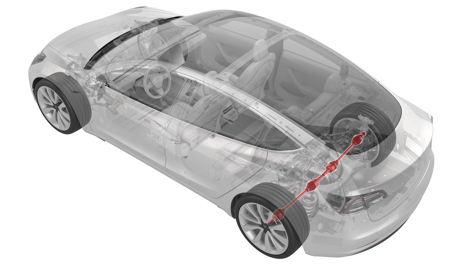
- 1134520-00-A Kit, EPB Release, Handheld
- 1129348-00-AXP-10 Power Supply, XP-10
- 1133386-00-A Tool, Axle Extraction, Model 3
- 1096075-00-AHub Puller Tool, Hydraulic
SPECIAL TOOLS
Kit, EPB Release, Handheld (1134520-00-A) |
XP-10 Power Supply, XP-10 (1129348-00-A) |
Tool, Axle Extraction, Model 3 (1133386-00-A) |
Hub Puller Tool, Hydraulic (1096075-00-A) |
Remove
-
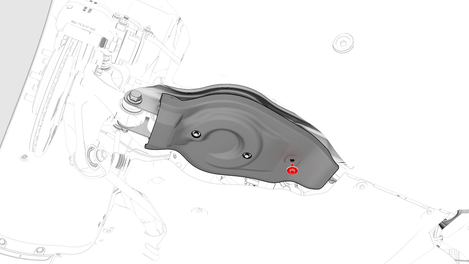
Remove the bolt that attaches the LH rear suspension cover.
-
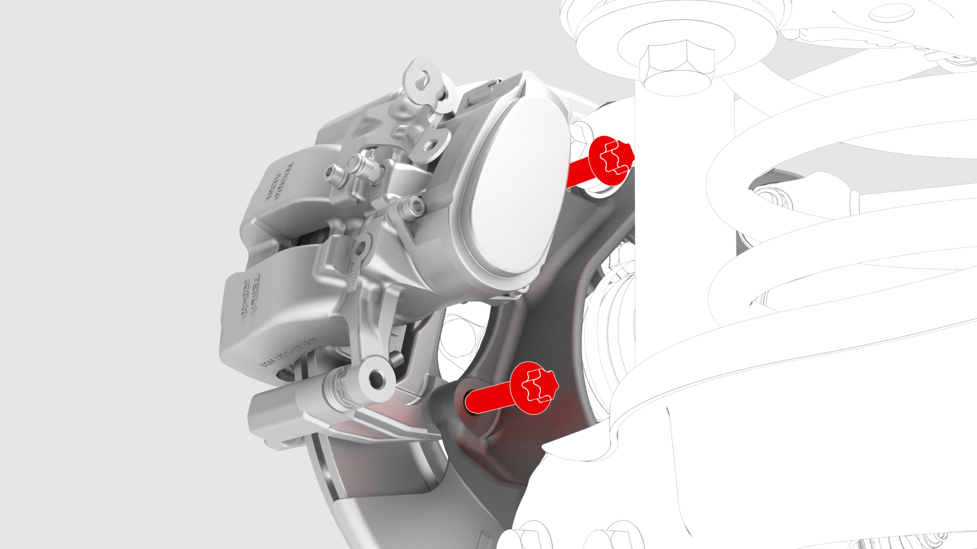
Remove and discard the bolts that attach the LH rear caliper bracket to the knuckle.
-
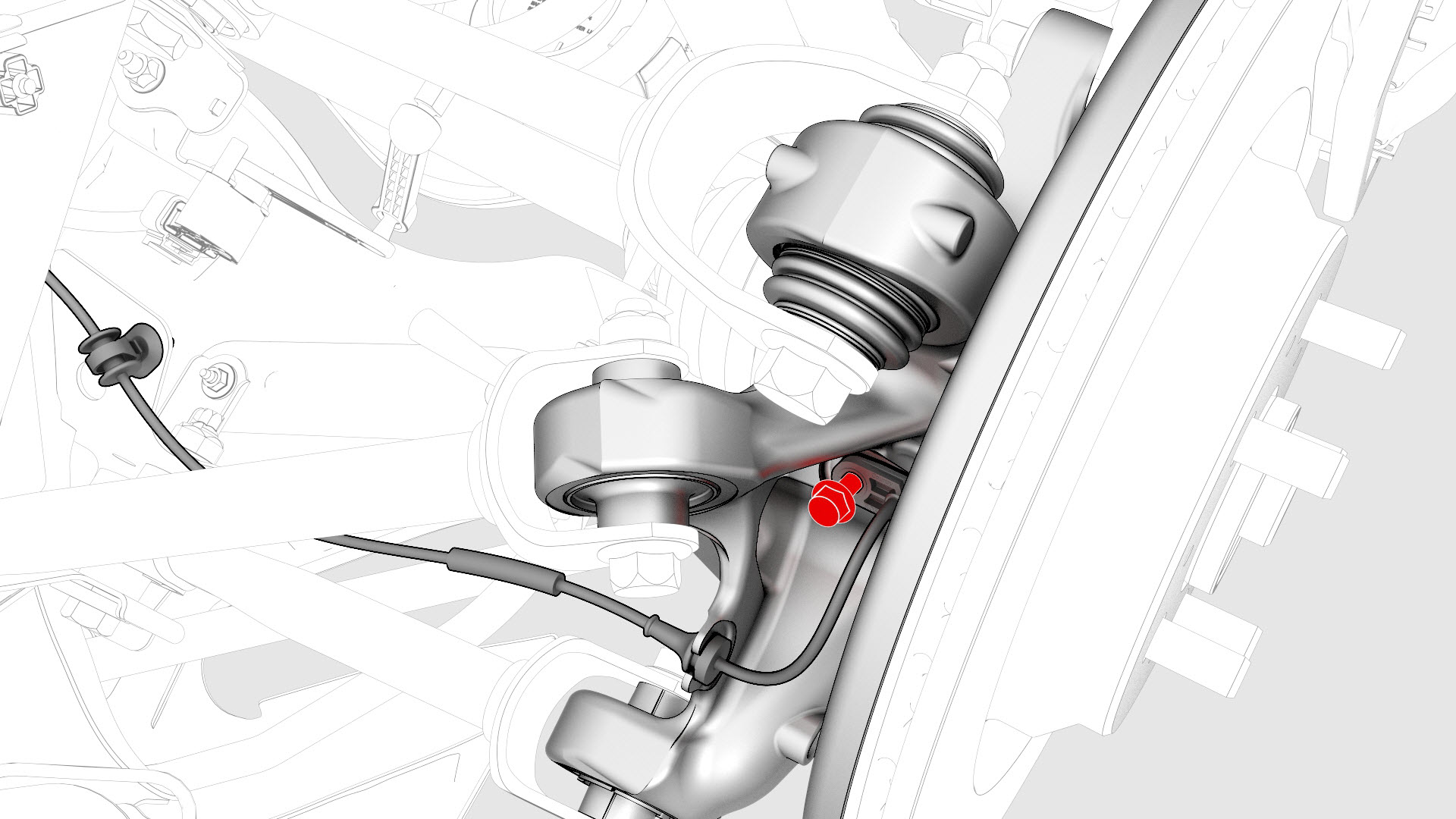
Remove and discard the bolt that attaches the rear LH ABS wheel speed sensor to the knuckle, and then remove the sensor from the knuckle.
-
Release the clip and remove the grommet that attach the rear LH ABS wheel speed sensor cable to the rear LH knuckle and subframe bracket.
-
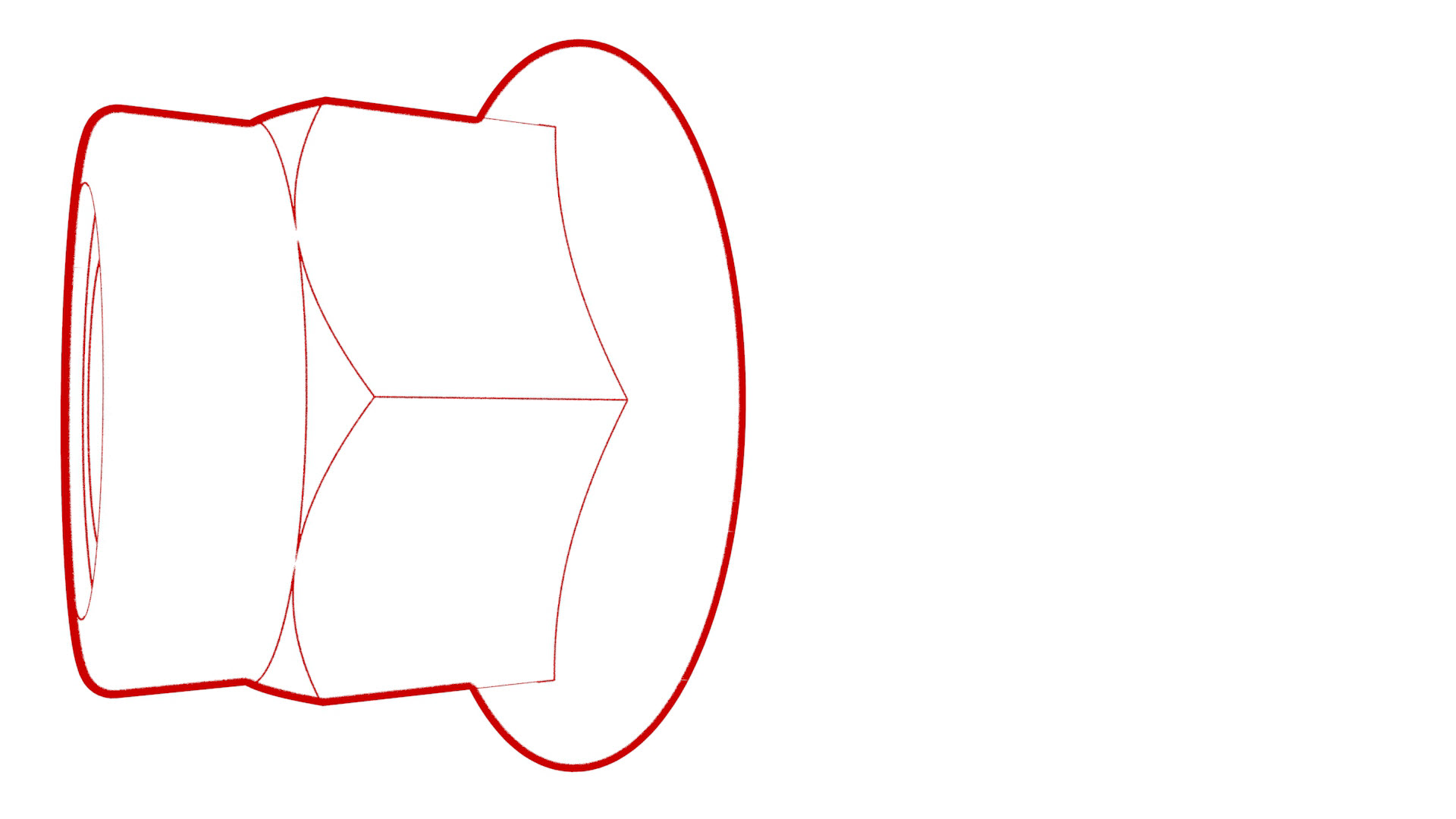
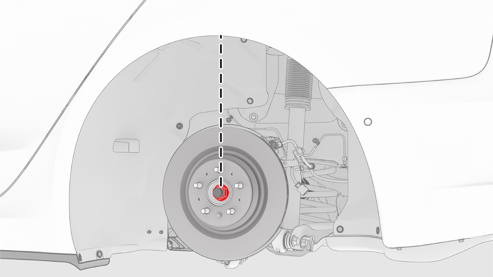
Remove and discard the nut, and remove the washer that attach the LH halfshaft to the hub assembly.
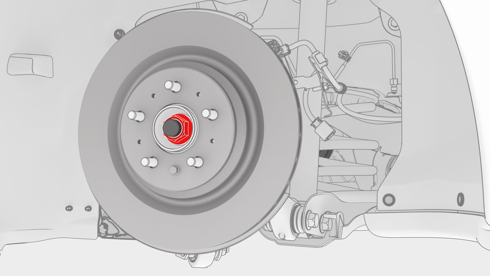
-
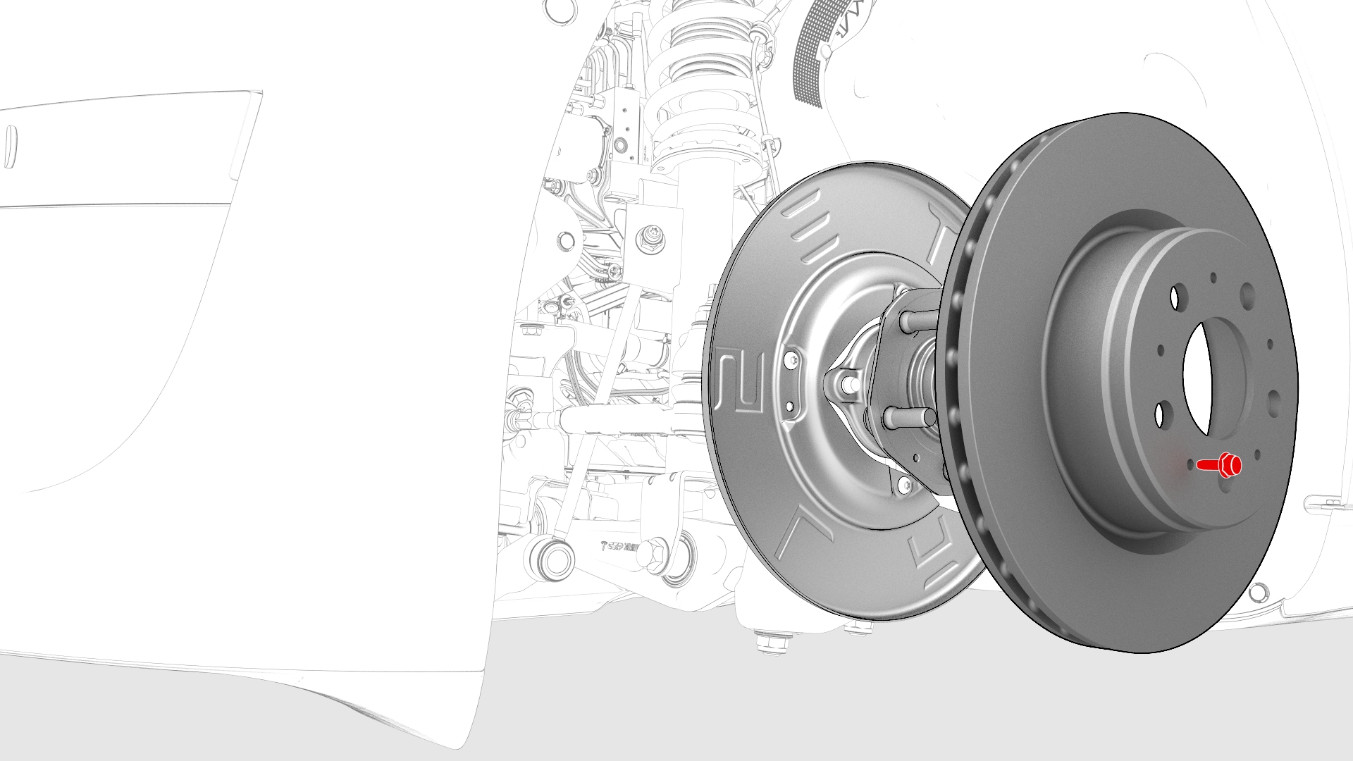
Remove the bolt that attaches the brake rotor to the hub.
 Note: Remove the lug nut previously installed for early production vehicles.
 -
Install the bolt that attaches the brake rotor to the hub.
 Torque 5 NmNote: Reinstall the lug nut previously installed for early production vehicles.
 -
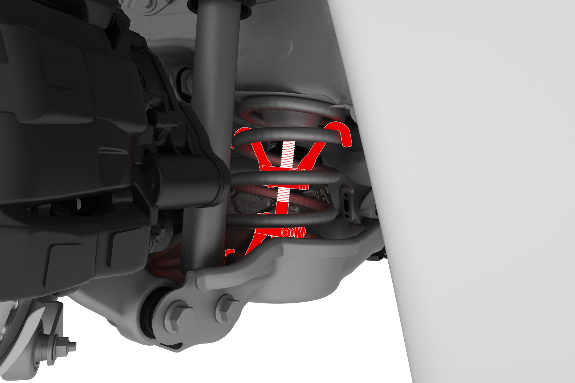
Install a spring compressor onto the LH rear coil spring. Line up the hooks per image and verify that the spindle goes through the body opening when the suspension is compressed.
-
Position a support stand underneath the LH rear suspension.

-
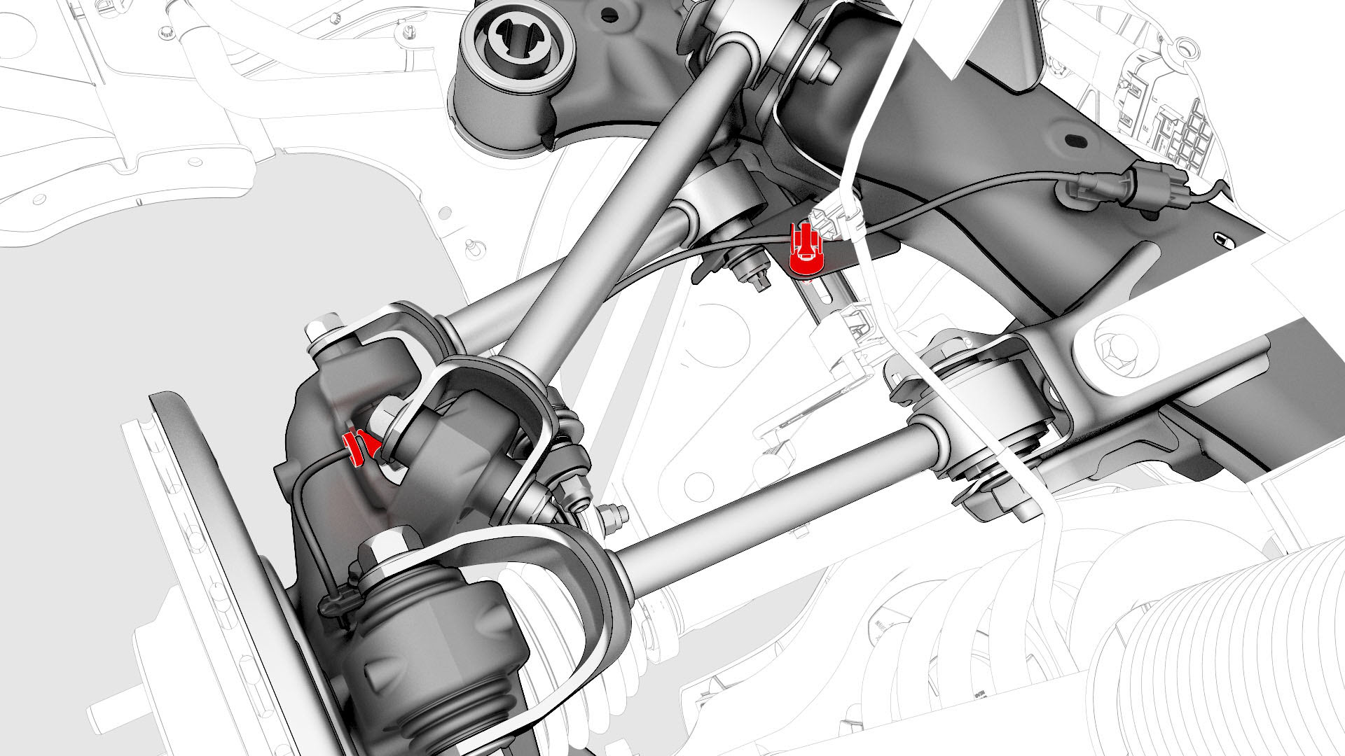
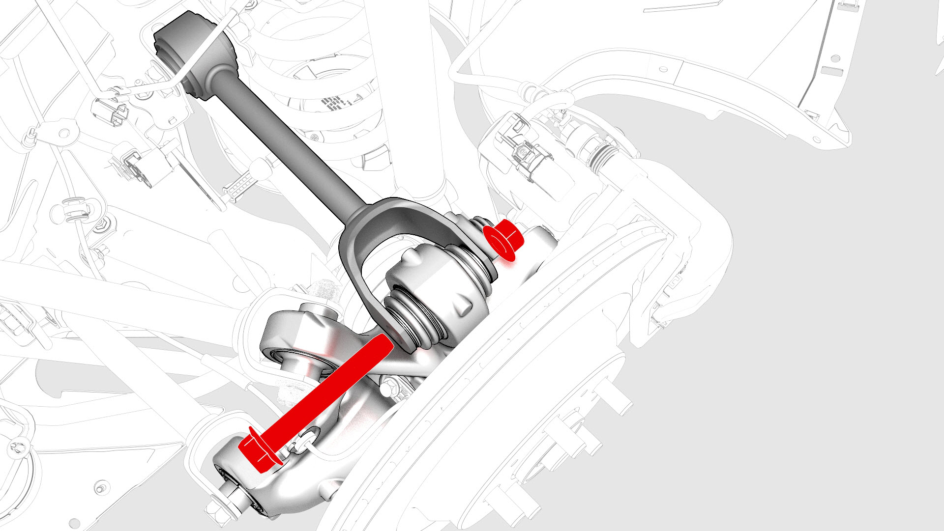
Remove the bolt and nut that attach the LH upper aft link to the knuckle.
-
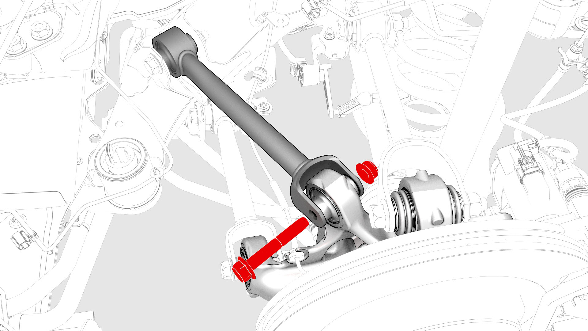
Remove the bolt and nut that attach the LH upper fore link to the knuckle.
-
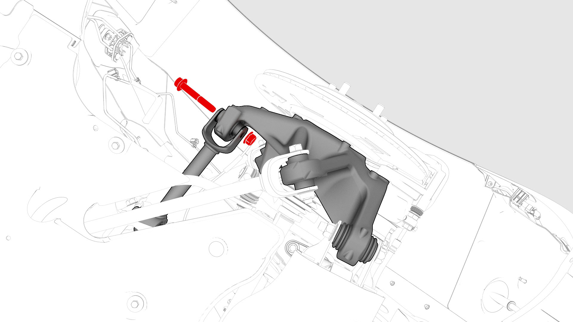
Remove the bolt and nut that attach the LH toe link to the knuckle.
-
Remove and discard the nut that attaches the rear stabilizer bar link to the rear stabilizer bar.
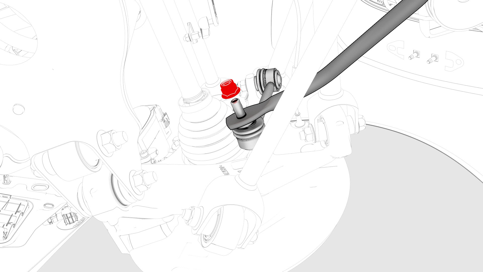 Note: Break the nut loose, and then counter-hold the ball joint with a 5 mm hex wrench.
 -
Remove the bolts that attach the LH rear damper at the top mount.
 Torque 41 Nm
-
Remove the halfshaft from the vehicle, and then install a halfshaft plug into the opening of the gearbox.
| 1 | Raise the vehicle on a 2 post lift. See Raise Vehicle - 2 Post Lift. | ||
| 2 | Loosen the LH rear wheel lug nuts, but do not remove the wheel at this time. See Wheel (Remove and Install). | ||
| 3 | Loosen the LH rear axle nut, but do not remove the nut at this time. | ||
| 4 | Remove the mid aero shield panel. See Panel - Aero Shield - Mid (Remove and Replace). | ||
| 5 | Remove the bolt that attaches the LH rear suspension cover. | |
| 6 | Remove the LH rear wheel. | ||
| 7 | Remove the LH rear wheel arch liner. See Wheel Arch Liner - Rear - LH (Remove and Replace). | ||
| 8 | Release the LH rear caliper parking brake. See Parking Brake - Caliper - Rear - LH (Release). | ||
| 9 | Remove and discard the bolts that attach the LH rear caliper bracket to the knuckle. | |
| 10 | Remove the LH rear brake caliper from the LH rear suspension, and then allow it to hang from the body using an S-hook. | ||
| 11 | Remove and discard the bolt that attaches the rear LH ABS wheel speed sensor to the knuckle, and then remove the sensor from the knuckle. | |
| 12 | Release the clip and remove the grommet that attach the rear LH ABS wheel speed sensor cable to the rear LH knuckle and subframe bracket. | |
| 13 | Remove and discard the nut, and remove the washer that attach the LH halfshaft to the hub assembly. | |
| 14 | Remove the bolt that attaches the brake rotor to the hub. Note: Remove the lug nut previously installed for early production vehicles.
| |
| 15 | Install the hub puller onto the LH rear rotor, and then install and hand-tighten the puller washers (x5) and the lug nuts (x5) onto the rotor studs. | ||
| 16 | Use the hub puller to free the halfshaft from the hub splines. Note: The halfshaft is removed at a later step.
| ||
| 17 | Remove the lug nuts (x5) and the puller washers (x5) from the LH rear rotor studs, and then remove the hub puller from the rotor. | ||
| 18 | Install the bolt that attaches the brake rotor to the hub. Torque 5 Nm Note: Reinstall the lug nut previously installed for early production vehicles.
| |
| 19 | Install a spring compressor onto the LH rear coil spring. Line up the hooks per image and verify that the spindle goes through the body opening when the suspension is compressed. | |
| 20 | Position a support stand underneath the LH rear suspension. | |
| 21 | Remove the bolt and nut that attach the LH upper aft link to the knuckle. | |
| 22 | Remove the bolt and nut that attach the LH upper fore link to the knuckle. | |
| 23 | Remove the bolt and nut that attach the LH toe link to the knuckle. | |
| 24 | Remove and discard the nut that attaches the rear stabilizer bar link to the rear stabilizer bar. Note: Break the nut loose, and then counter-hold the ball joint with a 5 mm hex wrench.
| |
| 25 | Remove the bolts that attach the LH rear damper at the top mount. Torque 41 Nm | |
| 26 | Lower the support stand to gain access for halfshaft removal. | ||
| 27 | Separate the halfshaft from the hub assembly, and then move the halfshaft aside. | ||
| 28 | Install the axle extraction tool between the rear drive unit and the inner joint of the LH halfshaft, and then strike the handle end of the extraction tool with a dead blow hammer to unseat the halfshaft. | ||
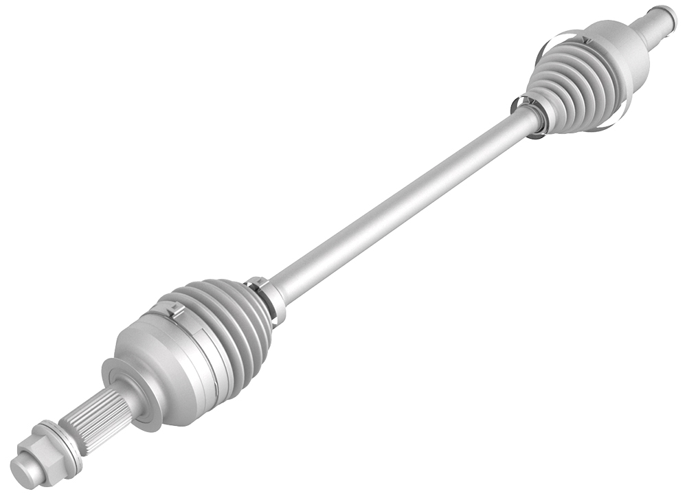
| 29 | Remove the halfshaft from the vehicle, and then install a halfshaft plug into the opening of the gearbox. |
Install
-
Apply approximately 1 gram of Molykote M-77 Lubricant Paste only to the hub mating face on the outboard side of the LH rear drive unit halfshaft.
 Caution:Do not apply any lubricant to the halfshaft splines. If lubricant is mistakenly applied, wipe the splines clean with a shop towel.
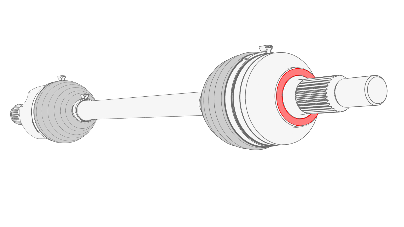
-
Use the support stand to raise the LH rear suspension.
-
With an assistant, install and hand-tighten the bolt and nut that attach the LH toe link to the knuckle.
-
With an assistant, installl and hand-tighten the bolt and nut that attach the LH upper fore link to the knuckle.
-
With an assistant, install and hand-tighten the bolt and nut that attach the LH upper aft link to the knuckle.
-
Install a new nut to attach the rear stabilizer bar link to the rear stabilizer bar, and then mark the nut with a paint pen.
 Torque 55 NmNote: Counter-hold the ball joint with a 5 mm hex wrench.
 -
Install the bolts that attach the LH rear damper at the top mount.Torque 41 Nm
-
Raise the support stand to simulate vehicle at ride height.
Note: Make sure that the support stand do not block access to adjust the spring compressor or suspension bolts.Note: Use the rear ride height torque gauge to verify that the rear suspension is set to ride height specifications and adjust the support stand or spring compressor tool , if necessary.
-
Measure the distance between the bottom of the quarter panel to the center of the rear axle to make sure that the rear suspension is set to ride height: The distance should measure 378 mm.
-
Tighten the bolt and nut that attach the LH toe link to the knuckle, and then mark the bolt and nut with a paint pen.
 Torque 76 Nm
 -
Tighten the bolt and nut that attach the LH upper fore link to the knuckle.Torque 76 Nm
-
Tighten the bolt and nut that attach the LH upper aft link to the knuckle, and then mark the bolt and nut with a paint pen.Torque 134 Nm
-
Remove the spring compressor from the LH coil spring.
-
Install the LH rear suspension cover to the lower aft link, and then install the bolt that attaches the suspension cover to the link.
 Torque 6 Nm
 -
Install the rear LH ABS wheel speed sensor to the LH rear knuckle, and then install a new bolt to secure the sensor to the knuckle.
 Torque 5 Nm
 -
Install the grommet and fasten the clip that attach the rear LH ABS wheel speed sensor cable to the rear LH knuckle and subframe bracket.
-
Install the bolts that attach the LH rear caliper bracket to the knuckle.
 Torque 80 Nm
 -
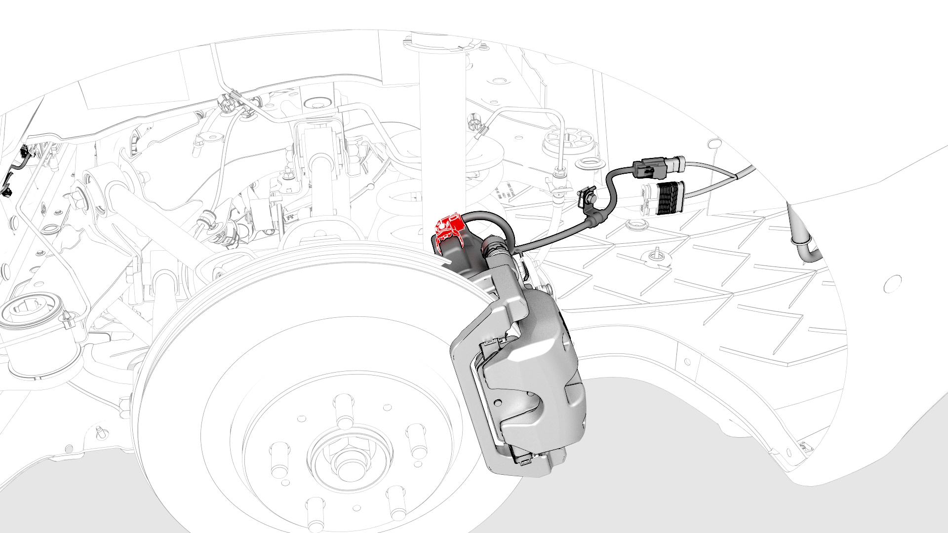
Install the bolt that attaches the electrical harness bracket to the LH rear brake caliper.
 Torque 5 Nm
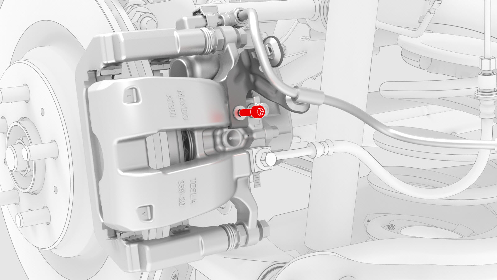
-
Connect the electrical harness to the LH rear brake caliper connector.
-
Tighten the LH rear axle nut.Torque 245 Nm
-
Tighten the wheel lug nuts.Torque 175 Nm
| 1 | Apply approximately 1 gram of Molykote M-77 Lubricant Paste only to the hub mating face on the outboard side of the LH rear drive unit halfshaft. Caution: Do not apply any lubricant to the halfshaft splines. If lubricant is mistakenly applied, wipe the splines clean with a shop towel.
| |
| 2 | Remove the halfshaft plug from the gearbox, and then install the halfshaft into the rear drive unit. | ||
| 3 | Swing out the upper section of the knuckle and mate the halfshaft to the hub. | ||
| 4 | Use the support stand to raise the LH rear suspension. | |
| 5 | Install the washer, and install and hand-tighten a new nut to attach the halfshaft to the LH rear hub. | ||
| 6 | With an assistant, install and hand-tighten the bolt and nut that attach the LH toe link to the knuckle. | |
| 7 | With an assistant, installl and hand-tighten the bolt and nut that attach the LH upper fore link to the knuckle. | |
| 8 | With an assistant, install and hand-tighten the bolt and nut that attach the LH upper aft link to the knuckle. | |
| 9 | Install a new nut to attach the rear stabilizer bar link to the rear stabilizer bar, and then mark the nut with a paint pen. Torque 55 Nm Note: Counter-hold the ball joint with a 5 mm hex wrench.
| |
| 10 | Install the bolts that attach the LH rear damper at the top mount. Torque 41 Nm | |
| 11 | Raise the support stand to simulate vehicle at ride height. Note: Make sure that the support stand do not block access to adjust the spring compressor or suspension bolts.
Note: Use the rear ride height torque gauge to verify that the rear suspension is set to ride height specifications and adjust the support stand or spring compressor tool , if necessary.
| |
| 12 | Measure the distance between the bottom of the quarter panel to the center of the rear axle to make sure that the rear suspension is set to ride height: The distance should measure 378 mm. | |
| 13 | Tighten the bolt and nut that attach the LH toe link to the knuckle, and then mark the bolt and nut with a paint pen. Torque 76 Nm | |
| 14 | Tighten the bolt and nut that attach the LH upper fore link to the knuckle. Torque 76 Nm | |
| 15 | Tighten the bolt and nut that attach the LH upper aft link to the knuckle, and then mark the bolt and nut with a paint pen. Torque 134 Nm | |
| 16 | Remove the support stand from underneath the LH rear suspension. | ||
| 17 | Remove the spring compressor from the LH coil spring. | |
| 18 | Install the LH rear suspension cover to the lower aft link, and then install the bolt that attaches the suspension cover to the link. Torque 6 Nm | |
| 19 | Hand-tighten the LH axle nut again. | ||
| 20 | Install the rear LH ABS wheel speed sensor to the LH rear knuckle, and then install a new bolt to secure the sensor to the knuckle. Torque 5 Nm | |
| 21 | Install the grommet and fasten the clip that attach the rear LH ABS wheel speed sensor cable to the rear LH knuckle and subframe bracket. | |
| 22 | Install the bolts that attach the LH rear caliper bracket to the knuckle. Torque 80 Nm | |
| 23 | Install the bolt that attaches the electrical harness bracket to the LH rear brake caliper. Torque 5 Nm | |
| 24 | Connect the electrical harness to the LH rear brake caliper connector. | |
| 25 | Install the LH rear wheel arch liner. See Wheel Arch Liner - Rear - LH (Remove and Replace). | ||
| 26 | Install the LH rear wheel, and then hand-tighten the lug nuts that attach the LH rear wheel to the hub. | ||
| 27 | Lower the vehicle and put the vehicle into Park. | ||
| 28 | Tighten the LH rear axle nut. Torque 245 Nm | |
| 29 | Tighten the wheel lug nuts. Torque 175 Nm | ||
| 30 | Install the LH rear wheel center cap or the hub cap. | ||
| 31 | Remove the vehicle from the lift. | ||
| 32 | Perform the four wheel alignment check. See Four Wheel Alignment (Check). |