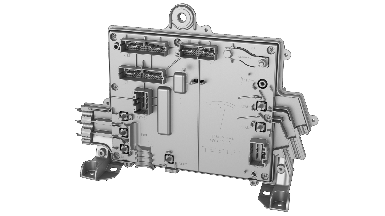
Module - Body Controller - Front (Dual Motor) (Remove and Replace)
Correction code 1715291217152912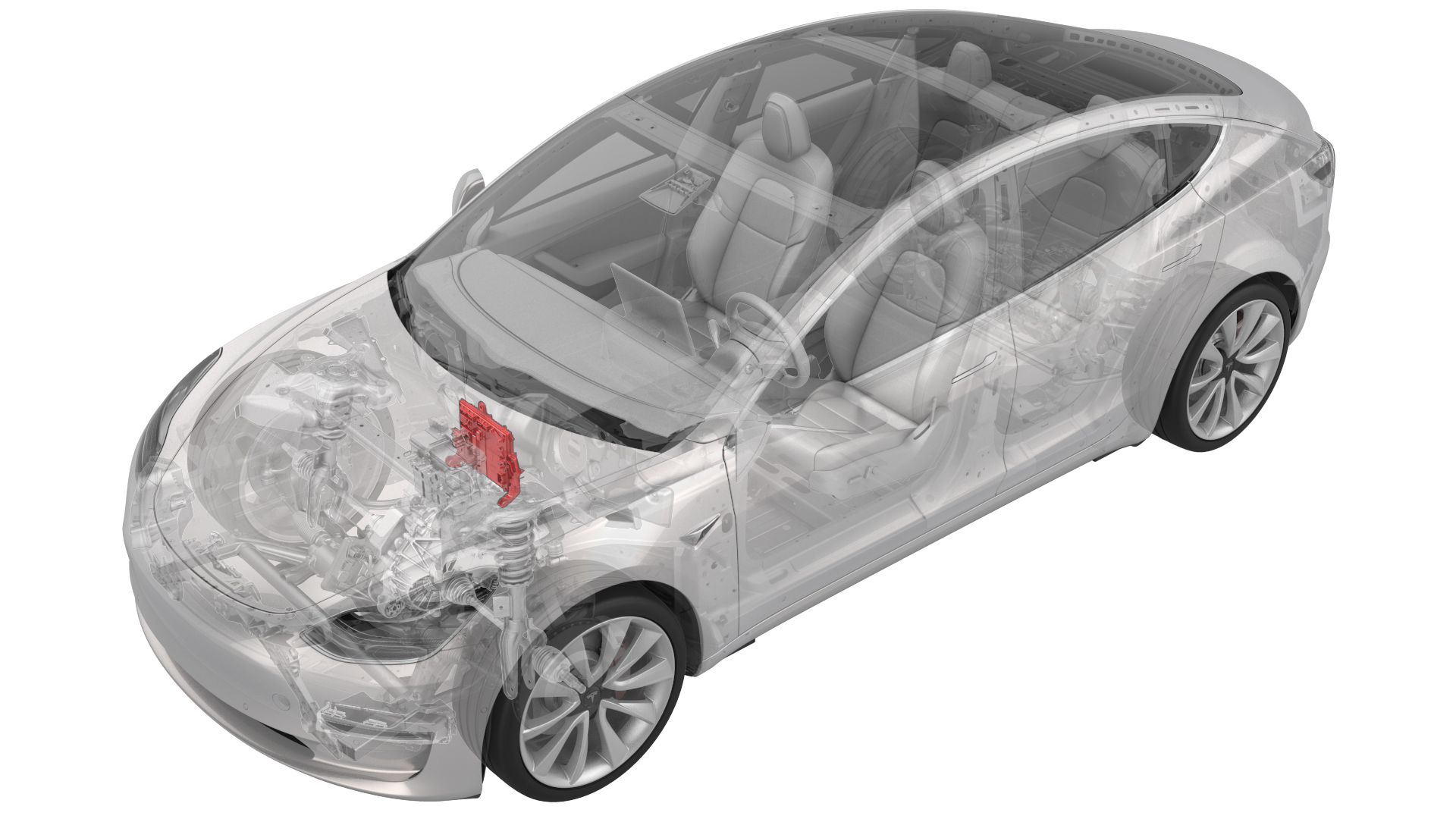
Remove
-
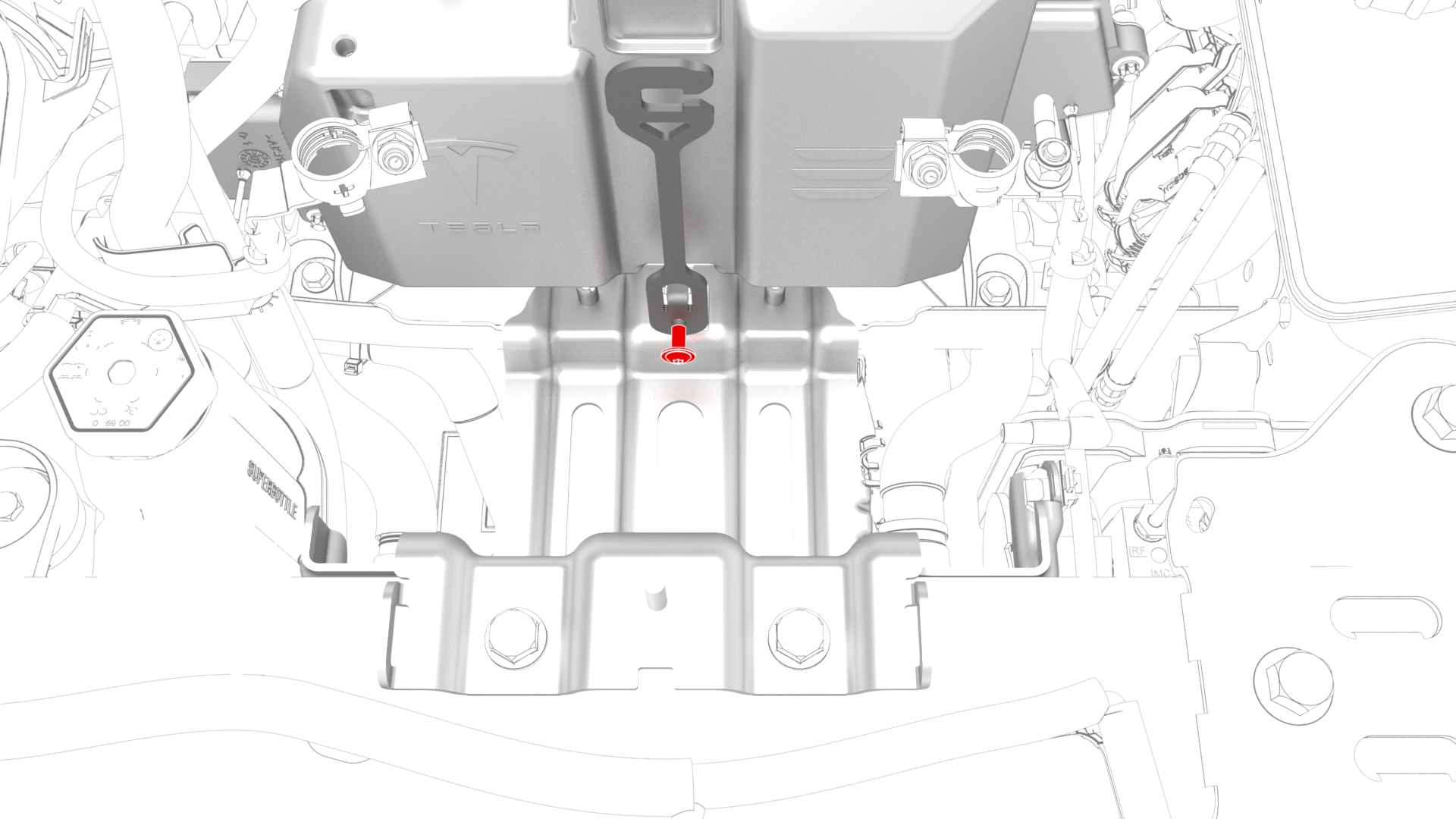
Remove the bolt that attaches the 12V battery rear hook tie down to the body, and then remove the tie down from the body.
-
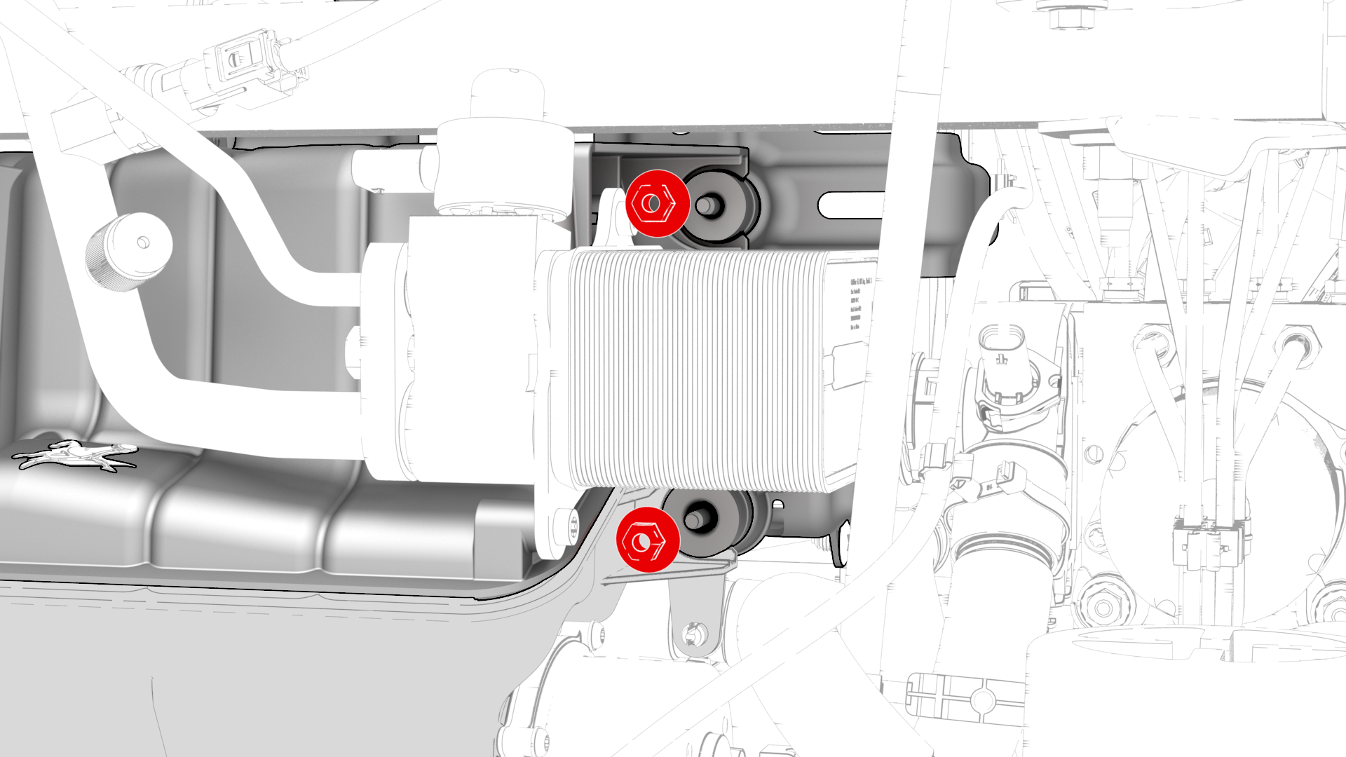
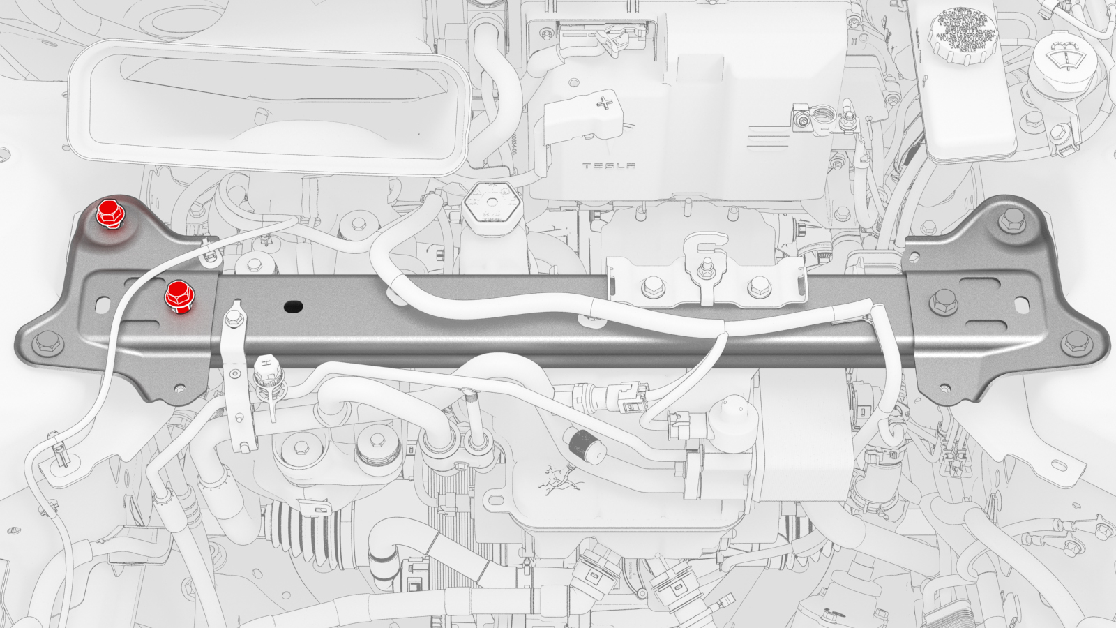
Remove the nuts (x2) that attach the superbottle to the thermal beam.
-
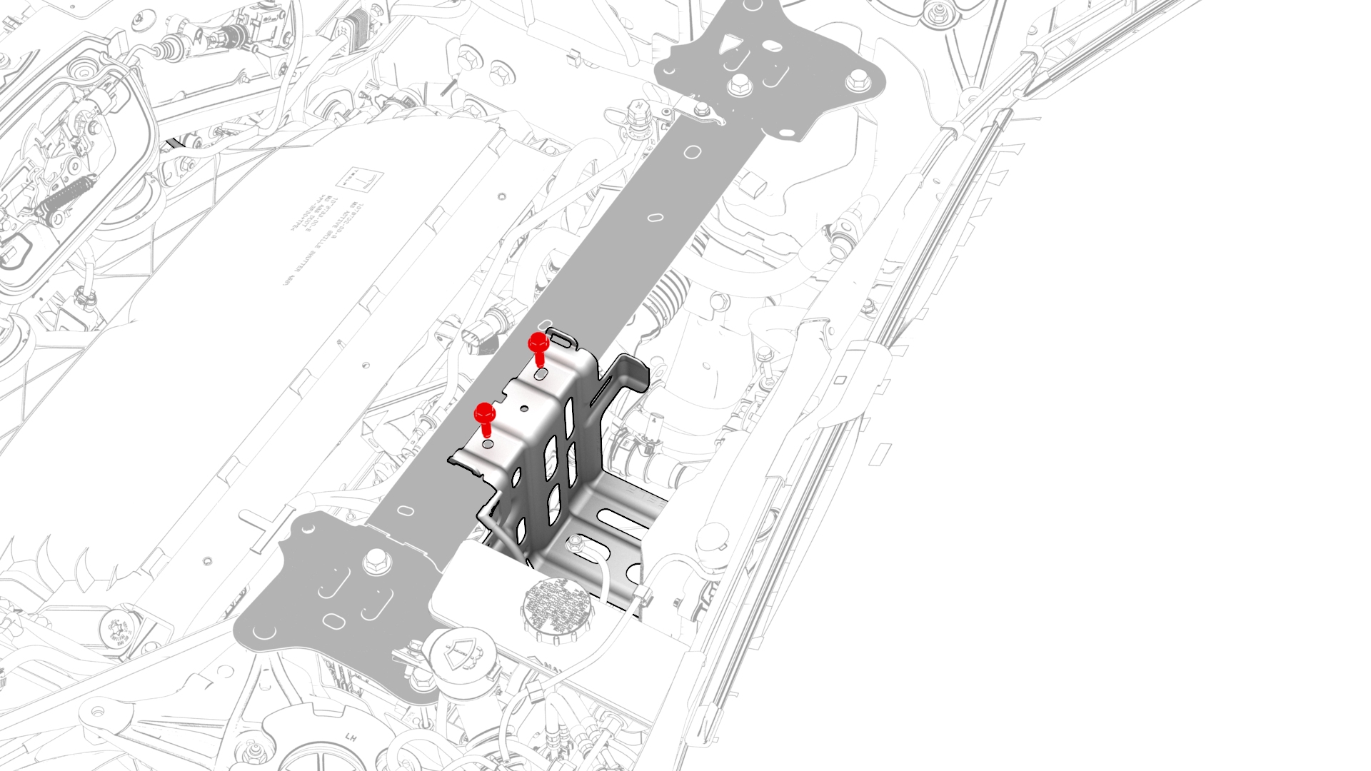
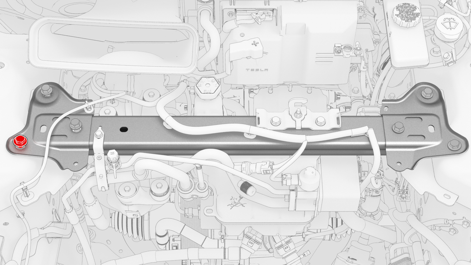
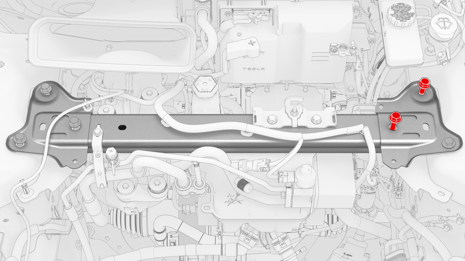
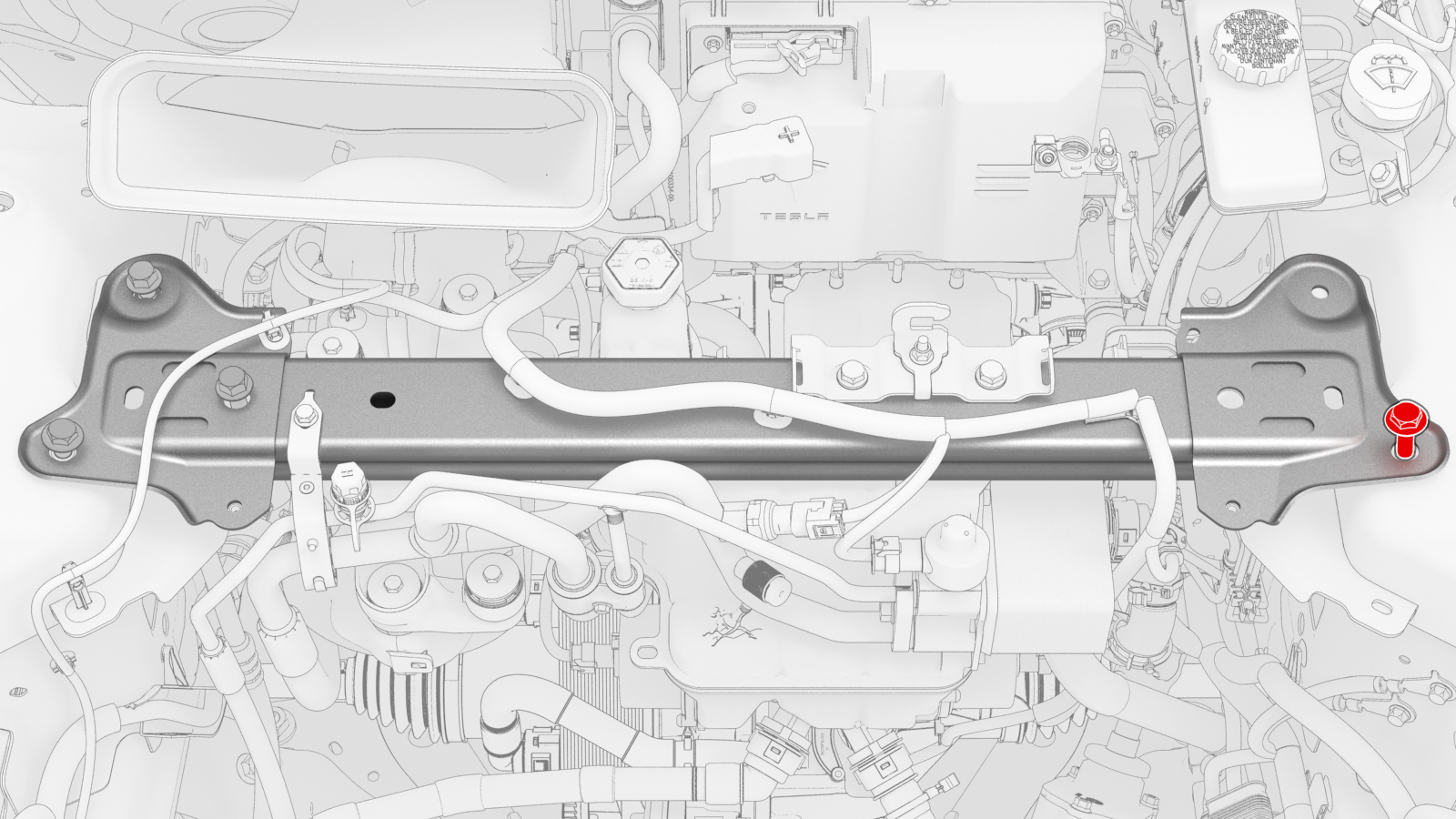
Remove the upper bolts (x2) that attach the battery bracket to the vehicle.
-
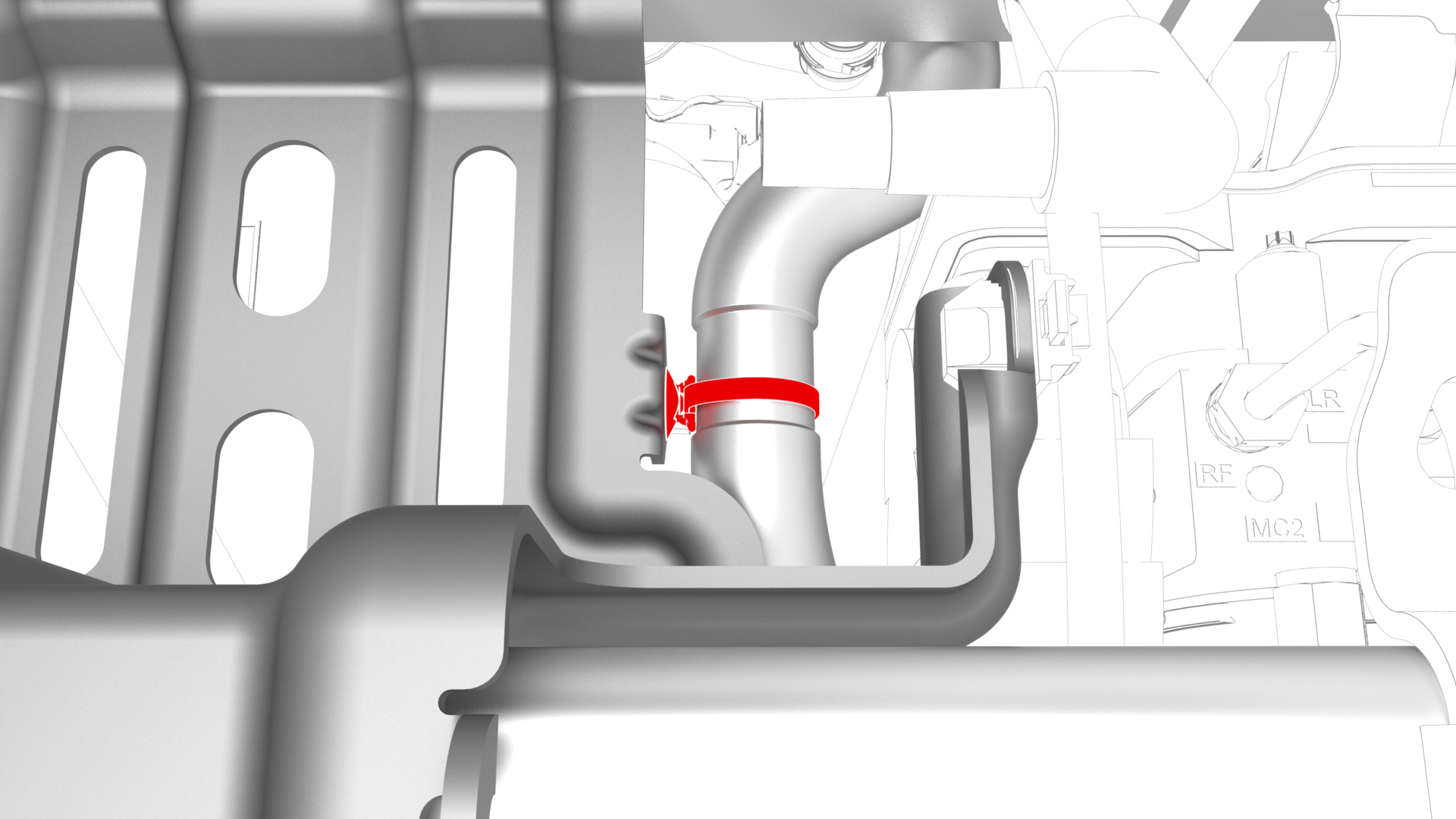
Release the clip that attaches the coolant hose to the 12V battery bracket.
-
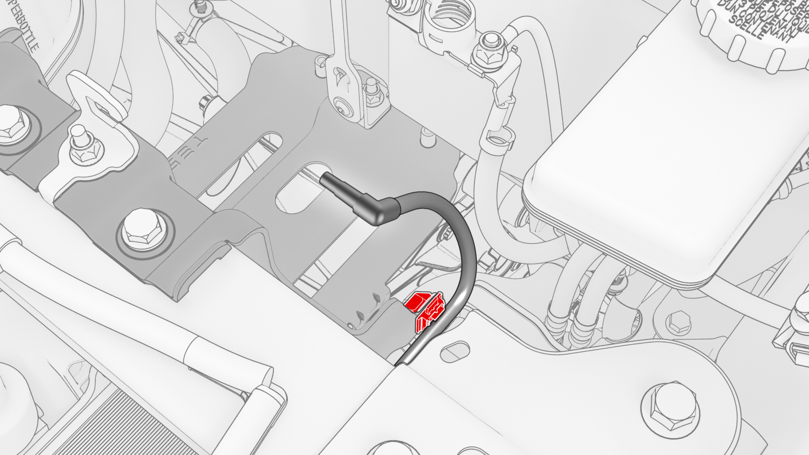
Release the clip that attaches the 12V battery vent hose to the 12V battery bracket.
-
Loosen the inner bolts that attach the shock tower brace to the RH shock tower.
-
Loosen the outer bolt that attaches the shock tower brace to the RH shock tower.
-
Remove the inner bolts that attach the shock tower brace to the LH shock tower.
-
Remove the outer bolt that attaches the shock tower brace to the LH shock tower.
-
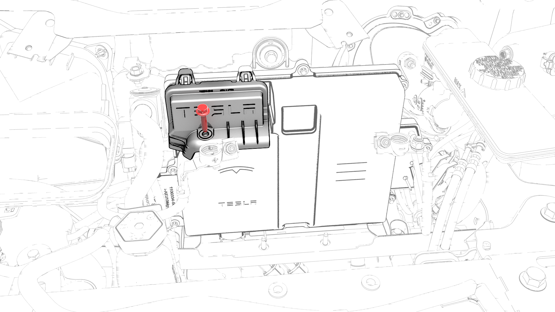
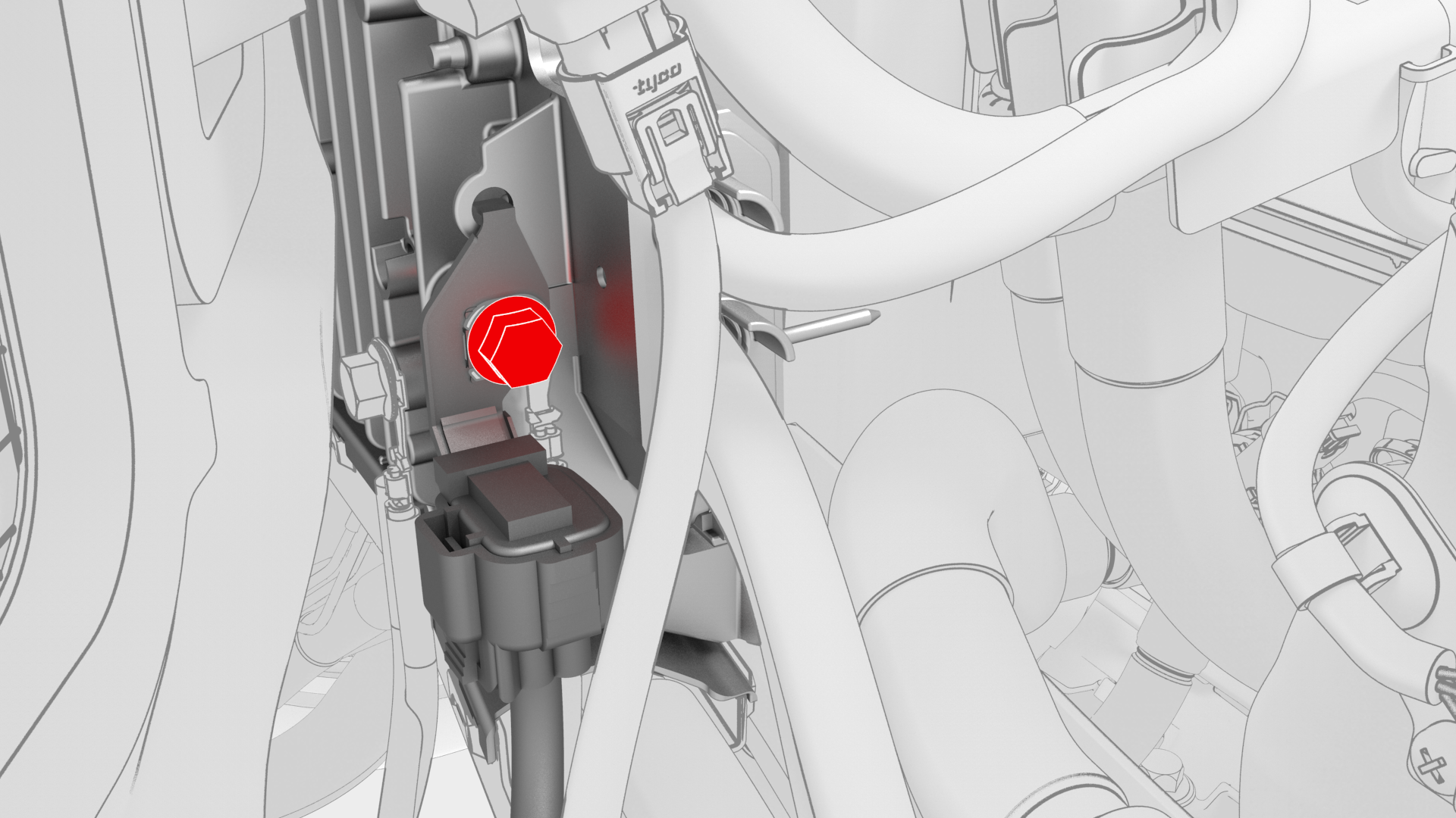
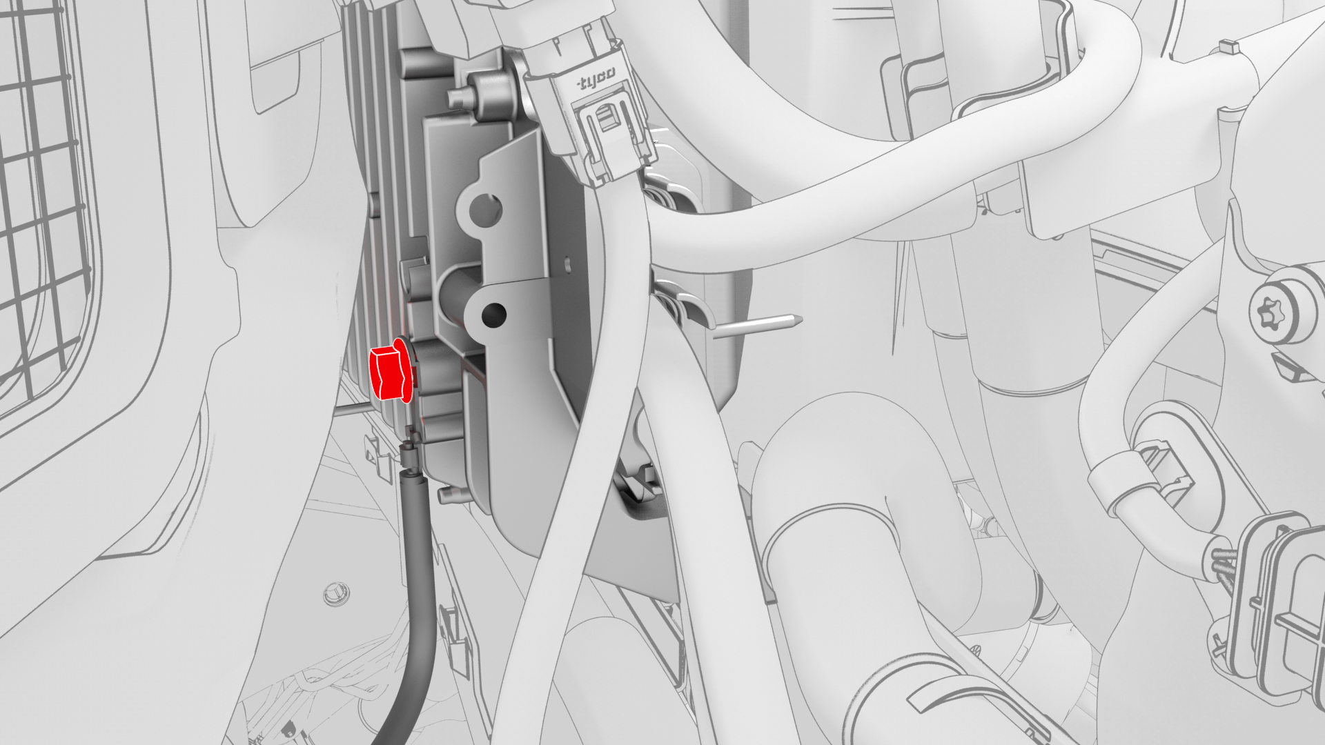
Remove the bolt that attaches the thermal harness cover to the front body controller module, and then remove the cover from the module.
-
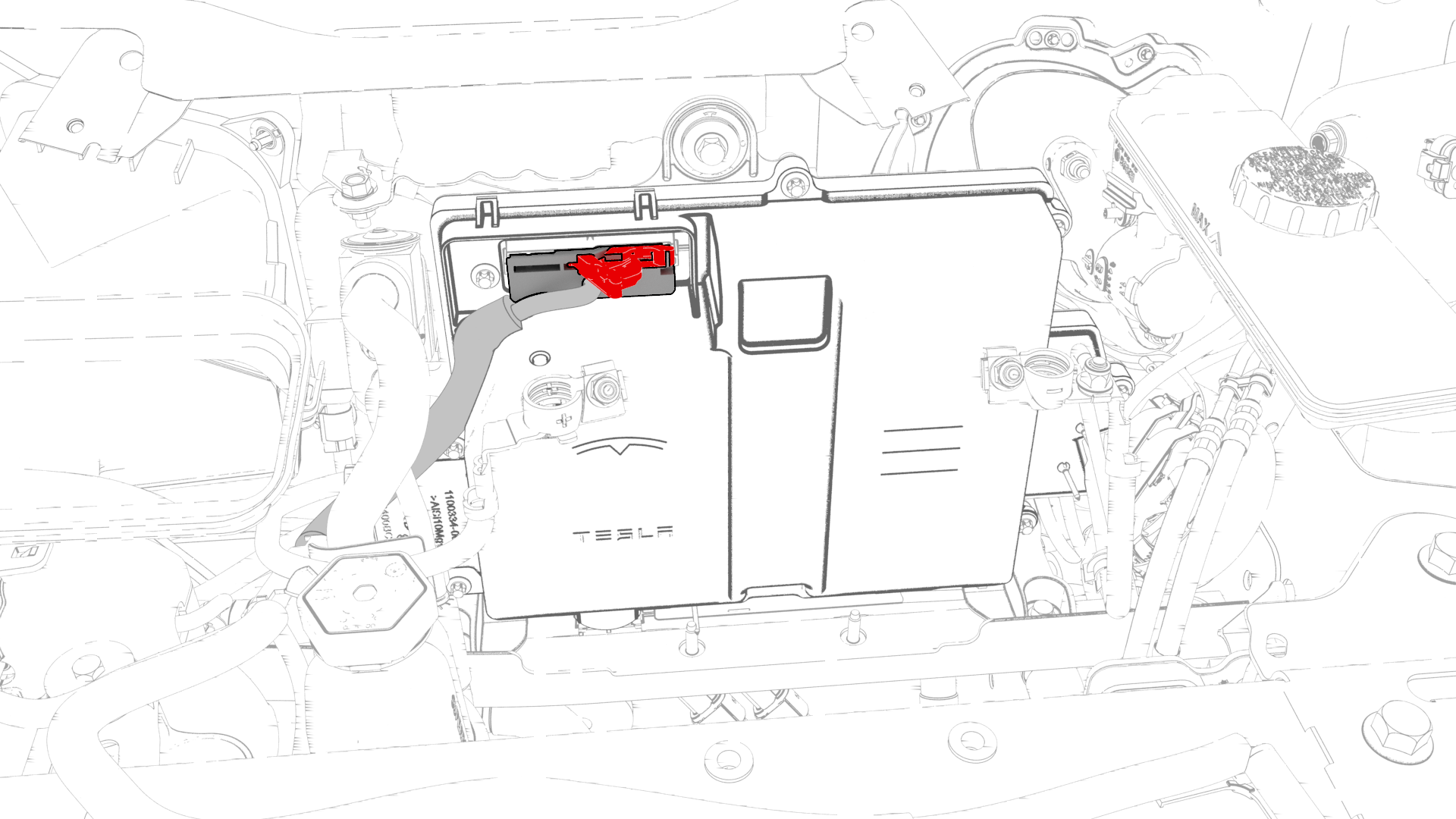
Disconnect the thermal harness from the front body controller module connector.
-
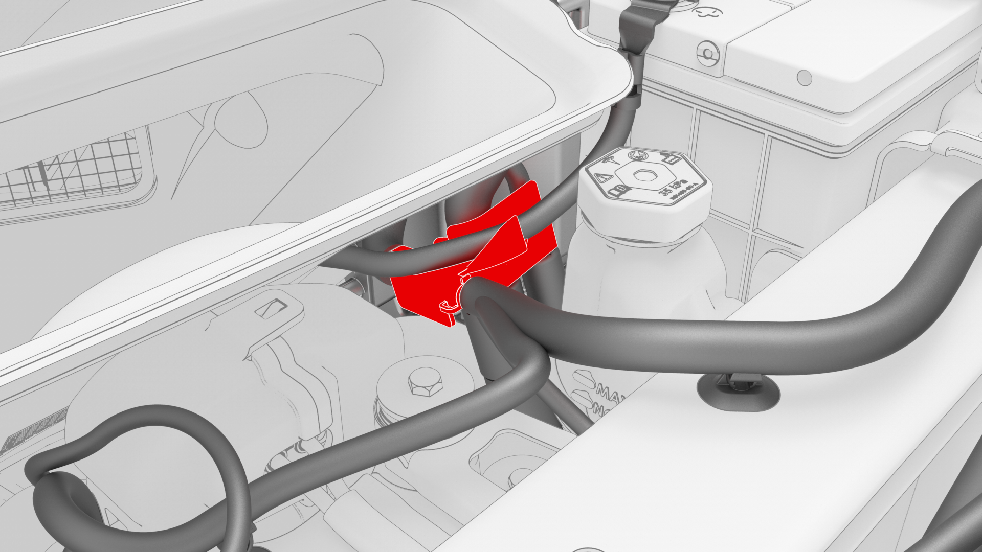
Release the clip that attaches the suction/liquid lines to the body near the TXV, and then move the electrical harness aside to gain access to the front body controller module.
-
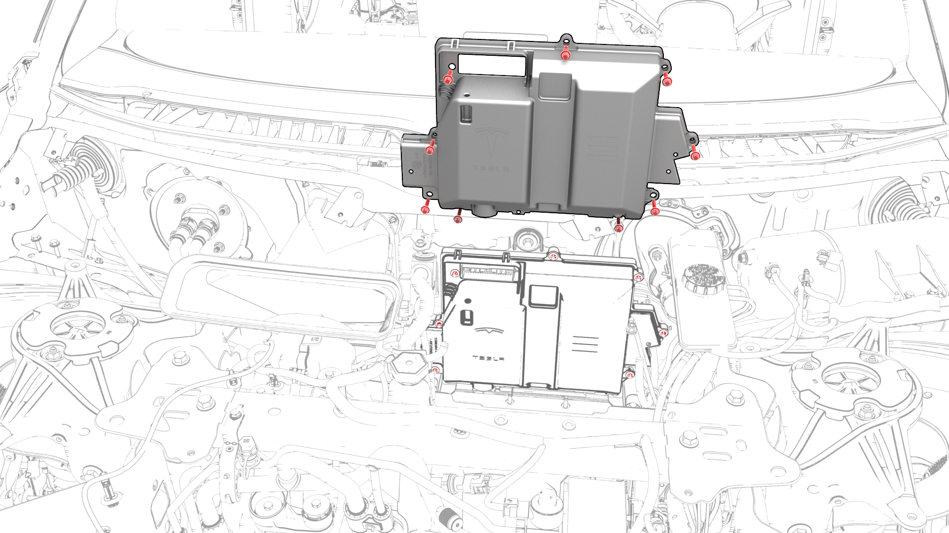
Remove the bolts (x9) that attach the front body controller module cover to the front body controller module, and then remove the cover.
-
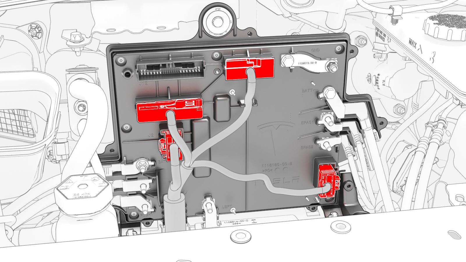
Disconnect the electrical harness from the front body controller module connectors (x4).
-
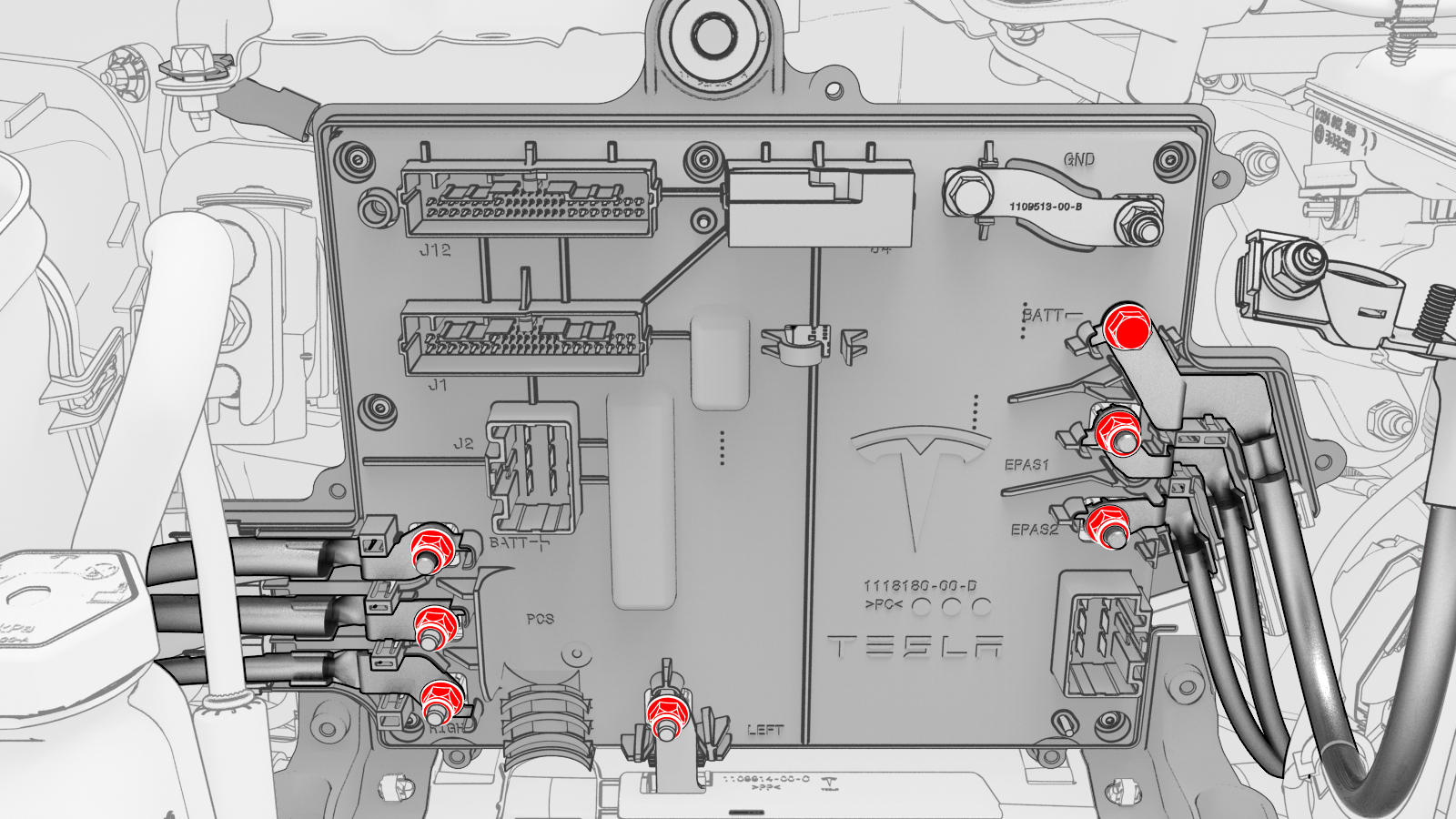
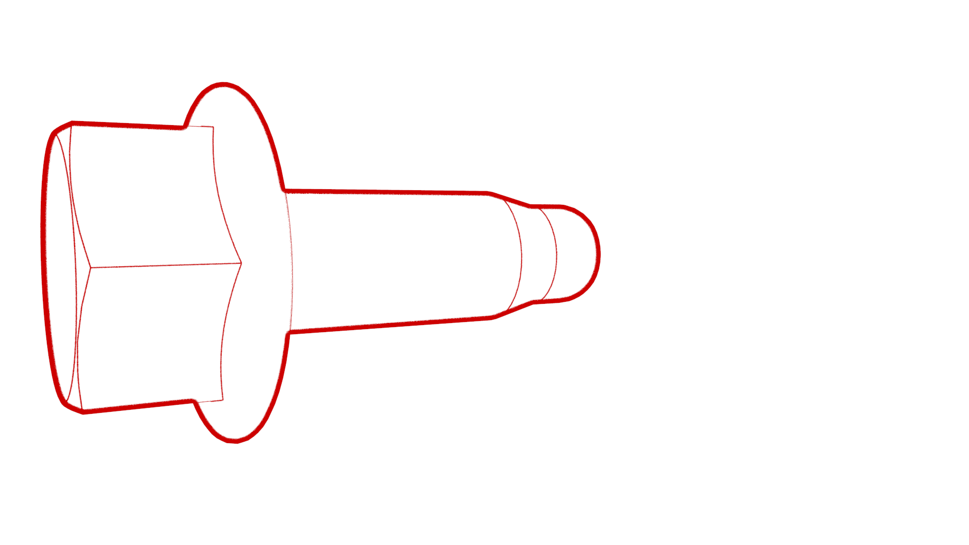
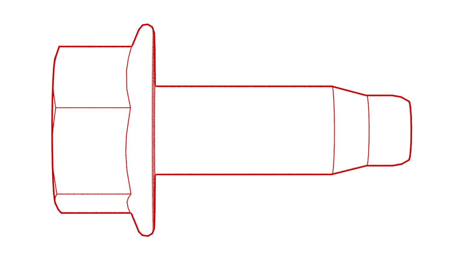
Remove and discard the nuts (x6) and bolt that attach the power and ground cables to the front body controller module.
-
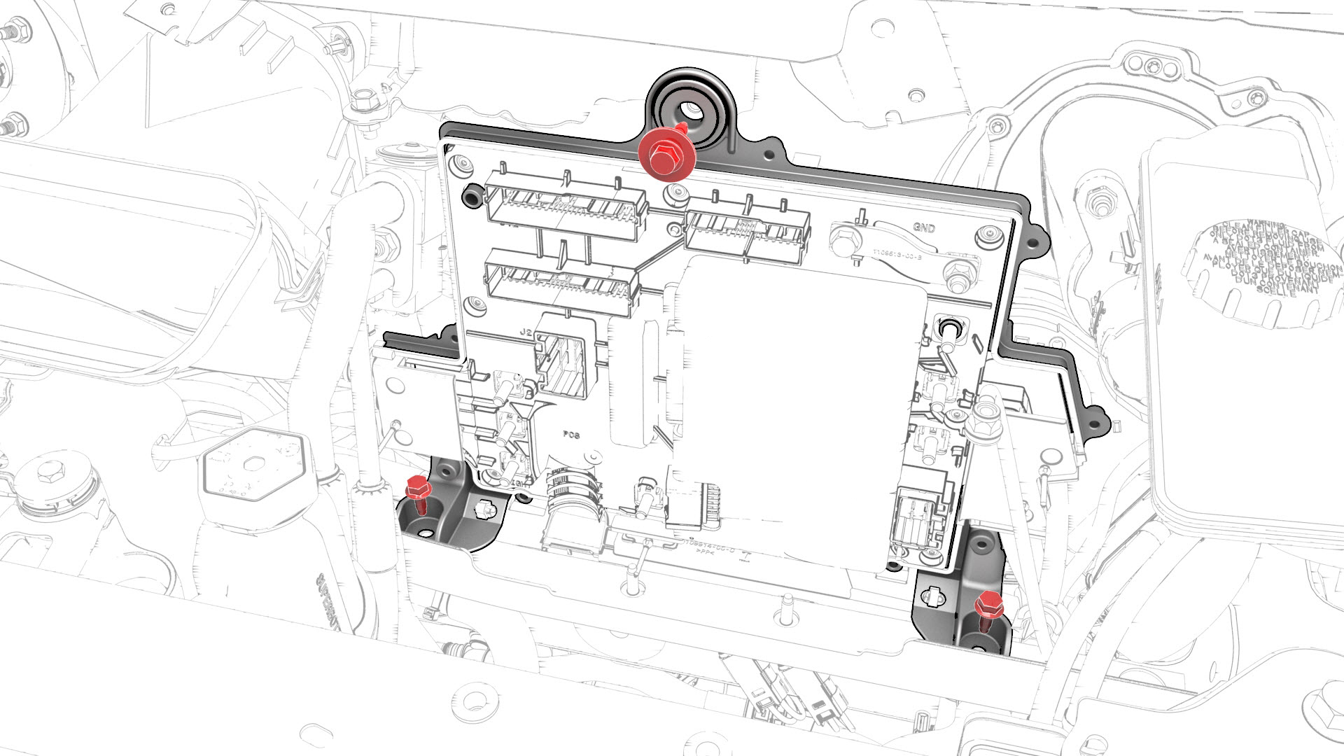
Remove the bolts (x3) that attach the front body controller module to the body.
-
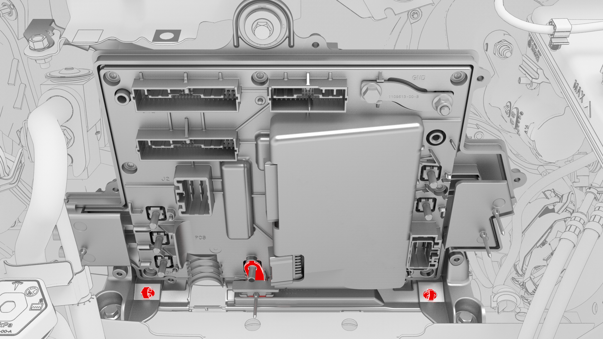
Release the clips (x2) that attach the bottom of the front body controller module to the body, and then remove the lower busbar from the stud.
-
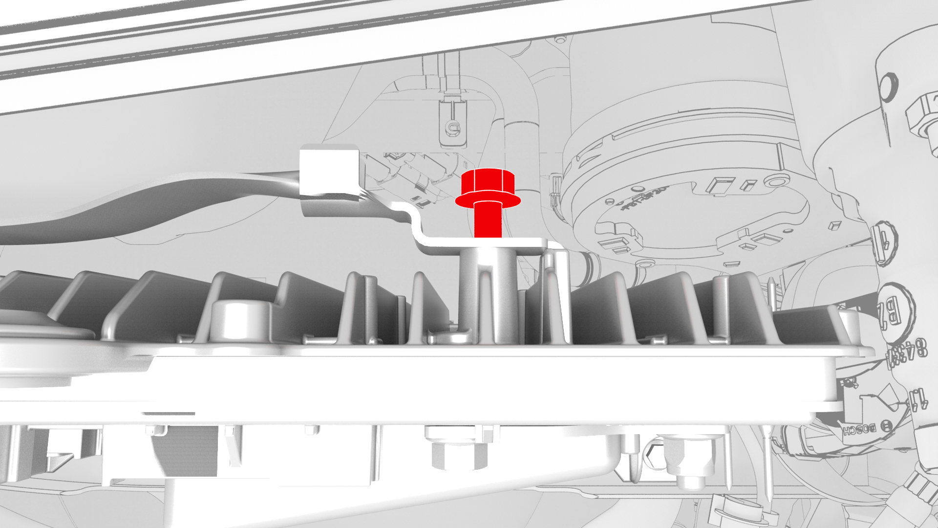
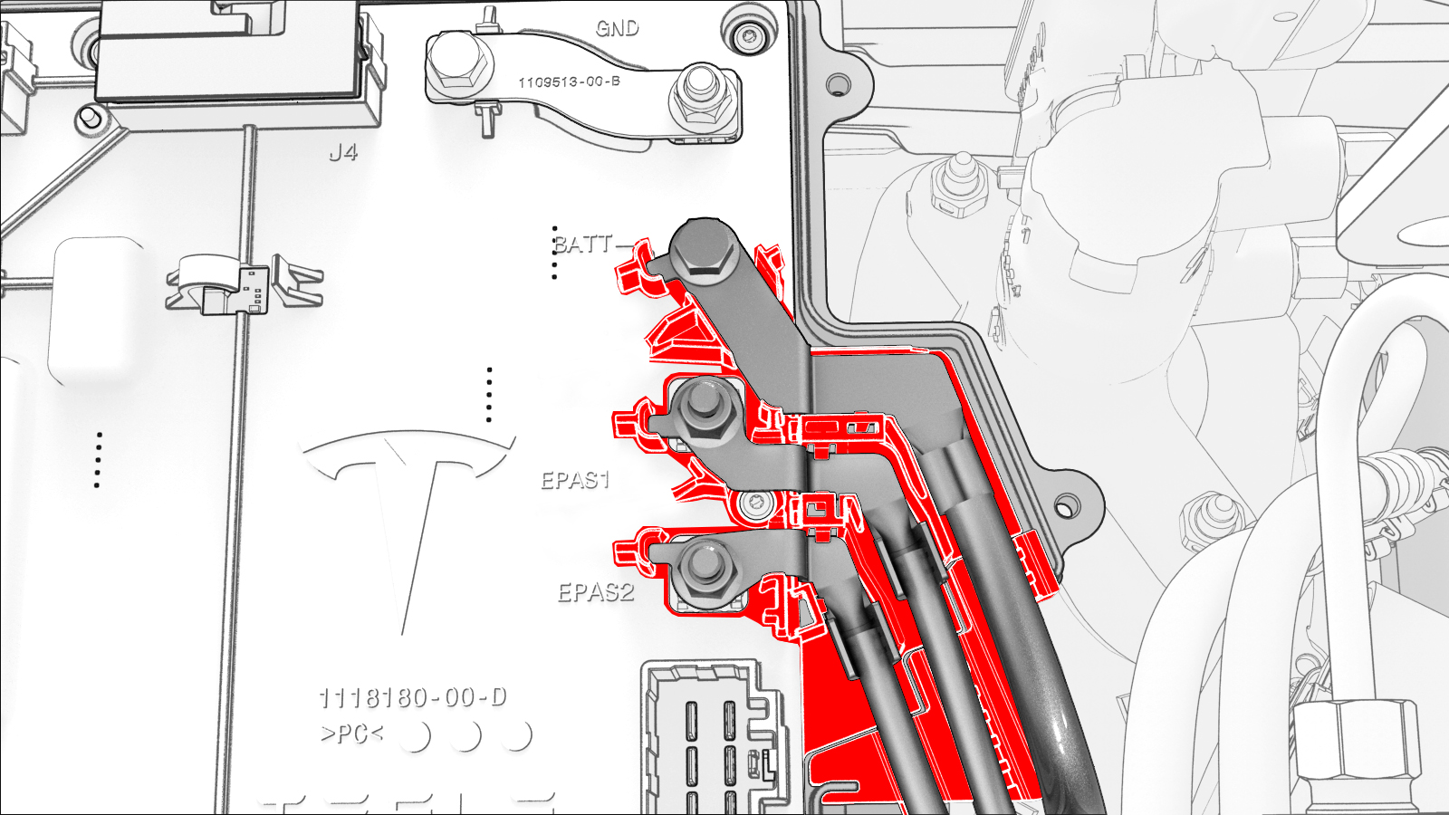
Remove the bolt that attaches the ground strap to the upper rear of the front body controller module, and then remove the ground strap from the module.
-
Remove the bolt that attaches the ground strap to the lower right side of the front body controller module, and then remove the ground strap from the module.
-
Remove the bolt that attaches the ground strap to the lower rear of the front body controller module, and then remove the ground strap from the module.
-
Remove the front body controller module from the vehicle.
| 1 | Remove the 2nd row lower seat cushion. See Seat Cushion - Lower - 2nd Row (Remove and Replace). | ||
| 2 | Remove the rear underhood apron. See Underhood Apron - Rear (Remove and Replace). | ||
| 3 | Remove the cabin intake duct. See Duct - Cabin Intake (Remove and Replace). | ||
| 4 | Remove the underhood storage unit. See Underhood Storage Unit (Remove and Replace). | ||
| 5 | Remove the LH and RH wiper arms. See Wiper Arms (Remove and Replace). | ||
| 6 | Remove the LH and RH shock tower covers. See Cover - Shock Tower - LH (Remove and Replace). | ||
| 7 | Remove the cowl screen panel. See Panel - Cowl Screen (Remove and Replace). | ||
| 8 | Disconnect 12V power. See 12V Power (Disconnect and Connect). | ||
| 9 | Remove the 12V auxiliary battery. See Battery - 12V (Remove and Replace). | ||
| 10 | Remove the bolt that attaches the 12V battery rear hook tie down to the body, and then remove the tie down from the body. | |
| 11 | Remove the nuts (x2) that attach the superbottle to the thermal beam. | |
| 12 | Remove the upper bolts (x2) that attach the battery bracket to the vehicle. | |
| 13 | Release the clip that attaches the coolant hose to the 12V battery bracket. | |
| 14 | Release the clip that attaches the 12V battery vent hose to the 12V battery bracket. | |
| 15 | Loosen the inner bolts that attach the shock tower brace to the RH shock tower. | |
| 16 | Loosen the outer bolt that attaches the shock tower brace to the RH shock tower. | |
| 17 | Remove the inner bolts that attach the shock tower brace to the LH shock tower. | |
| 18 | Remove the outer bolt that attaches the shock tower brace to the LH shock tower. | |
| 19 | Shift the LH side of the shock tower brace towards the front of the vehicle to increase working space. | ||
| 20 | Remove the bolt that attaches the thermal harness cover to the front body controller module, and then remove the cover from the module. | |
| 21 | Disconnect the thermal harness from the front body controller module connector. | |
| 22 | Release the clip that attaches the suction/liquid lines to the body near the TXV, and then move the electrical harness aside to gain access to the front body controller module. | |
| 23 | Remove the bolts (x9) that attach the front body controller module cover to the front body controller module, and then remove the cover. | |
| 24 | Disconnect the electrical harness from the front body controller module connectors (x4). | |
| 25 | Remove and discard the nuts (x6) and bolt that attach the power and ground cables to the front body controller module. | |
| 26 | Remove the bolts (x3) that attach the front body controller module to the body. | |
| 27 | Release the clips (x2) that attach the bottom of the front body controller module to the body, and then remove the lower busbar from the stud. | |
| 28 | Remove the bolt that attaches the ground strap to the upper rear of the front body controller module, and then remove the ground strap from the module. | |
| 29 | Remove the bolt that attaches the ground strap to the lower right side of the front body controller module, and then remove the ground strap from the module. | |
| 30 | Remove the bolt that attaches the ground strap to the lower rear of the front body controller module, and then remove the ground strap from the module. | |
| 31 | Remove the front body controller module from the vehicle. |
Install
-
Install the ground strap to the lower rear of the front body controller module, and then install the bolt that attaches the ground strap to the module.
 Torque 9 Nm
 -
Install the ground strap to the lower right side of the front body controller module, and then install the bolt that attaches the ground strap to the module.Torque 9 Nm
-
Install the ground strap to the upper rear of the front body controller module, and then install the bolt that attaches the ground strap to the module.Torque 9 Nm
-
Slide the busbar onto the lower stud, and then fasten the electrical harness clips (x2) to the bottom of the front body controller module.
-
Install the bolts (x3) that attach the front body controller module to the body.
 Torque 10 Nm
 Torque 10 Nm
 -
Install new nuts (x6) and new bolt to attach the power and ground cables to the front body controller module.
 Torque 8.5 Nm
 Torque 8.5 NmNote: Make sure that the terminal lugs fit in their channels neatly.
 -
Connect the electrical harness to the front body controller module connectors (x4).
-
Visually inspect that the power and the ground cables exit the front body controller module neatly in their respective channels, and parallel to each other.
 Caution:Make sure that no cables or wires will be pinched when the front body controller module cover is installed.
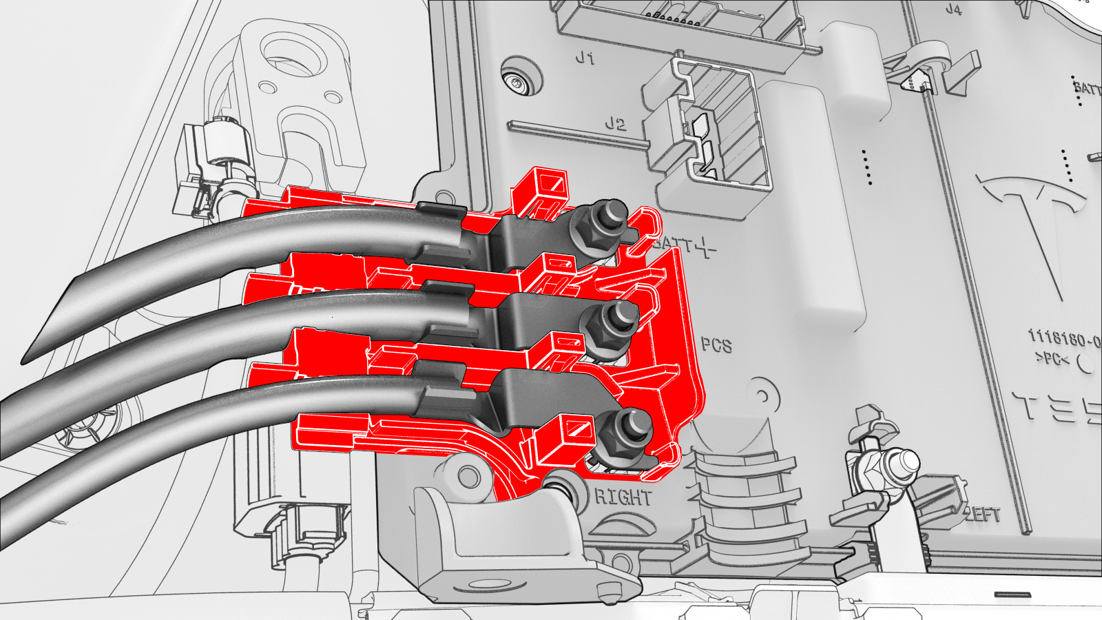
-
Install the front body controller module cover to the front body controller module, and then install the bolts (x9) that attach the cover to the module.
 Torque 6 Nm
 -
Connect the thermal harness to the front body controller module connector.
-
Fasten the clip that attaches the suction/liquid lines to the body near the TXV.
-
Install the thermal harness cover to the front body controller module, and then install the bolt that attaches the cover to the module.
 Torque 6 Nm
 -
Install the outer bolt that attaches the shock tower brace to the LH shock tower.
 Torque 62 Nm
 -
Install the inner bolts (x2) that attach the shock tower brace to the LH shock tower.
 Torque 67 Nm
 Torque 67 Nm
 -
Tighten the outer bolt that attaches the shock tower brace to the RH shock tower.Torque 62 Nm
-
Tighten the inner bolts (x2) that attach the shock tower brace to the RH shock tower.Torque 67 NmTorque 67 Nm
-
Fasten the clip that attaches the 12V battery vent hose to the 12V battery bracket.
-
Fasten the clip that attaches the coolant hose to the 12V battery bracket.
-
Install the upper bolts (x2) that attach the battery bracket to the vehicle.
 Torque 15 Nm
 -
Install the nuts (x2) that attach the superbottle to the thermal beam.
 Torque 8 Nm
 -
Install the 12V battery rear hook tie down to the body, and then install the bolt that attaches the tie down to the body.
 Torque 9 Nm
| 1 | Set the front body controller module where it installs into the vehicle, and then tilt the module forward | ||
| 2 | Install the ground strap to the lower rear of the front body controller module, and then install the bolt that attaches the ground strap to the module. Torque 9 Nm | |
| 3 | Install the ground strap to the lower right side of the front body controller module, and then install the bolt that attaches the ground strap to the module. Torque 9 Nm | |
| 4 | Install the ground strap to the upper rear of the front body controller module, and then install the bolt that attaches the ground strap to the module. Torque 9 Nm | |
| 5 | Slide the busbar onto the lower stud, and then fasten the electrical harness clips (x2) to the bottom of the front body controller module. | |
| 6 | Install the bolts (x3) that attach the front body controller module to the body. Torque 10 Nm Torque 10 Nm | |
| 7 | Install new nuts (x6) and new bolt to attach the power and ground cables to the front body controller module. Torque 8.5 Nm Torque 8.5 Nm Note: Make sure that the terminal lugs fit in their channels neatly.
| |
| 8 | Connect the electrical harness to the front body controller module connectors (x4). | |
| 9 | Visually inspect that the power and the ground cables exit the front body controller module neatly in their respective channels, and parallel to each other. Caution: Make sure that no cables or wires will be pinched when the front body controller module cover is installed.
| |
| 10 | Install the front body controller module cover to the front body controller module, and then install the bolts (x9) that attach the cover to the module. Torque 6 Nm | |
| 11 | Connect the thermal harness to the front body controller module connector. | |
| 12 | Fasten the clip that attaches the suction/liquid lines to the body near the TXV. | |
| 13 | Install the thermal harness cover to the front body controller module, and then install the bolt that attaches the cover to the module. Torque 6 Nm | |
| 14 | Shift the LH side of the shock tower brace rearward so that the bolt holes in the brace and shock tower align. | ||
| 15 | Install the outer bolt that attaches the shock tower brace to the LH shock tower. Torque 62 Nm | |
| 16 | Install the inner bolts (x2) that attach the shock tower brace to the LH shock tower. Torque 67 Nm Torque 67 Nm | |
| 17 | Tighten the outer bolt that attaches the shock tower brace to the RH shock tower. Torque 62 Nm | |
| 18 | Tighten the inner bolts (x2) that attach the shock tower brace to the RH shock tower. Torque 67 Nm Torque 67 Nm | |
| 19 | Fasten the clip that attaches the 12V battery vent hose to the 12V battery bracket. | |
| 20 | Fasten the clip that attaches the coolant hose to the 12V battery bracket. | |
| 21 | Install the upper bolts (x2) that attach the battery bracket to the vehicle. Torque 15 Nm | |
| 22 | Install the nuts (x2) that attach the superbottle to the thermal beam. Torque 8 Nm | |
| 23 | Install the 12V battery rear hook tie down to the body, and then install the bolt that attaches the tie down to the body. Torque 9 Nm | |
| 24 | Install the 12V auxiliary battery. See Battery - 12V (Remove and Replace). | ||
| 25 | Connect 12V power. See 12V Power (Disconnect and Connect). | ||
| 26 | Connect a laptop with Toolbox to the vehicle. | ||
| 27 | Use Toolbox to update the vehicle firmware. | ||
| 28 | In Toolbox, click the play button next to the "TESTRESET_ VCFRONT" and select Run, | ||
| 29 | Disconnect the laptop from the vehicle. | ||
| 30 | Install the cowl screen panel. See Panel - Cowl Screen (Remove and Replace). | ||
| 31 | Install the LH and RH shock tower covers. See Cover - Shock Tower - LH (Remove and Replace). | ||
| 32 | Install the LH and RH wiper arms. See Wiper Arms (Remove and Replace). | ||
| 33 | Install the underhood storage unit. See Underhood Storage Unit (Remove and Replace). | ||
| 34 | Install the cabin intake duct. See Duct - Cabin Intake (Remove and Replace). | ||
| 35 | Install the rear underhood apron. See Underhood Apron - Rear (Remove and Replace). | ||
| 36 | Install the 2nd row lower seat cushion. See Seat Cushion - Lower - 2nd Row (Remove and Replace). |