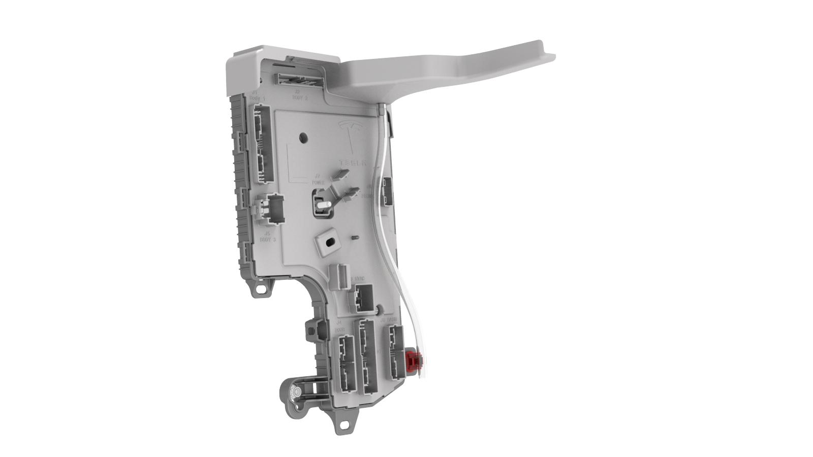
Module - Body Controller - LH (Remove and Replace)
Correction code 1715210217152102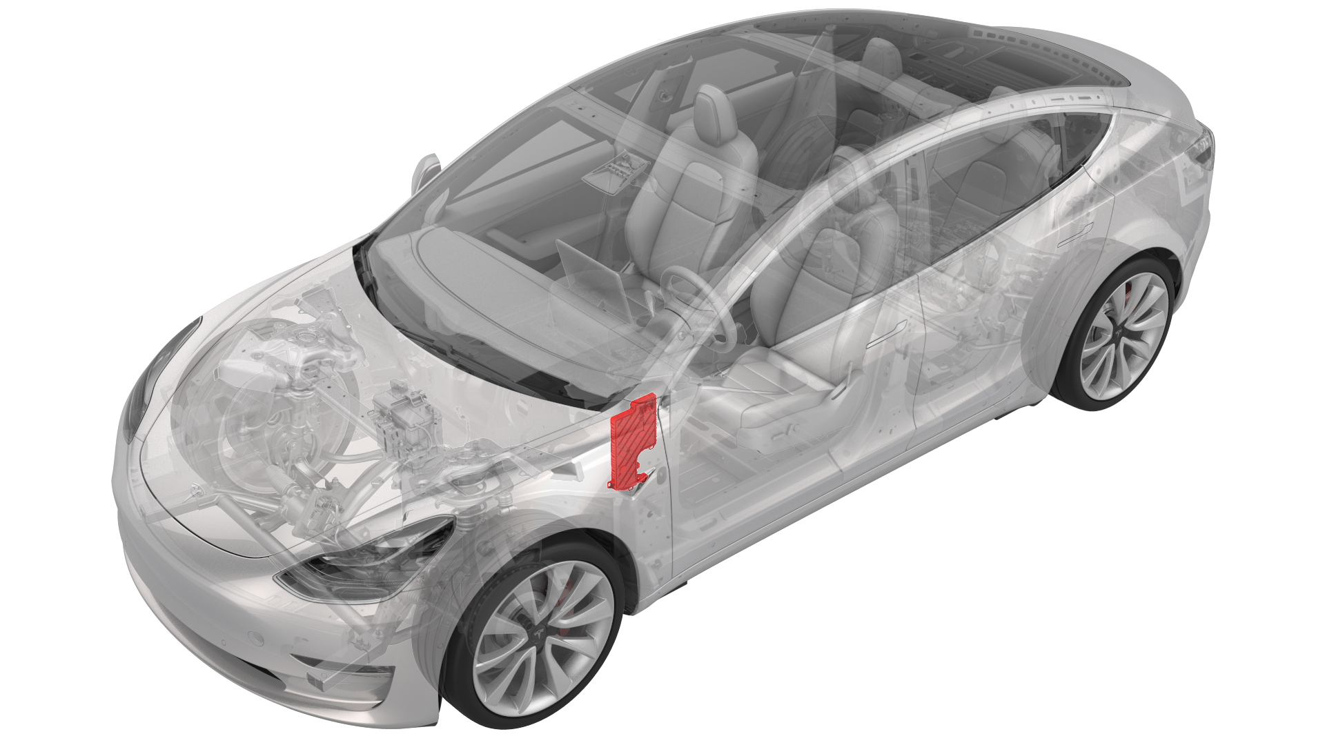
Remove
-
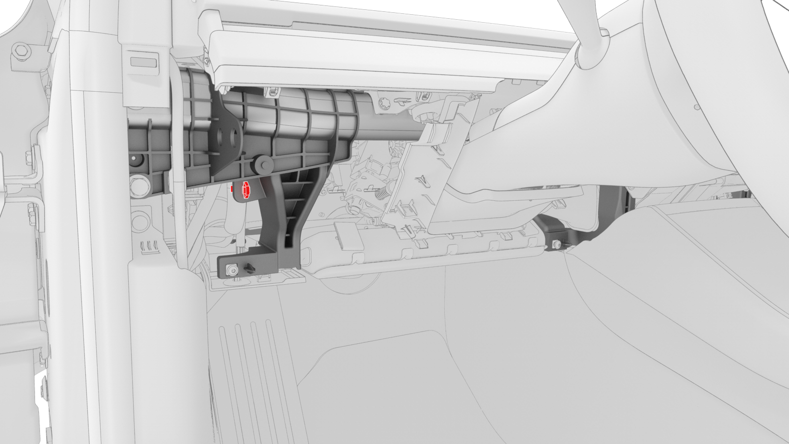
Release the electrical harness clip from the IP carrier.
-
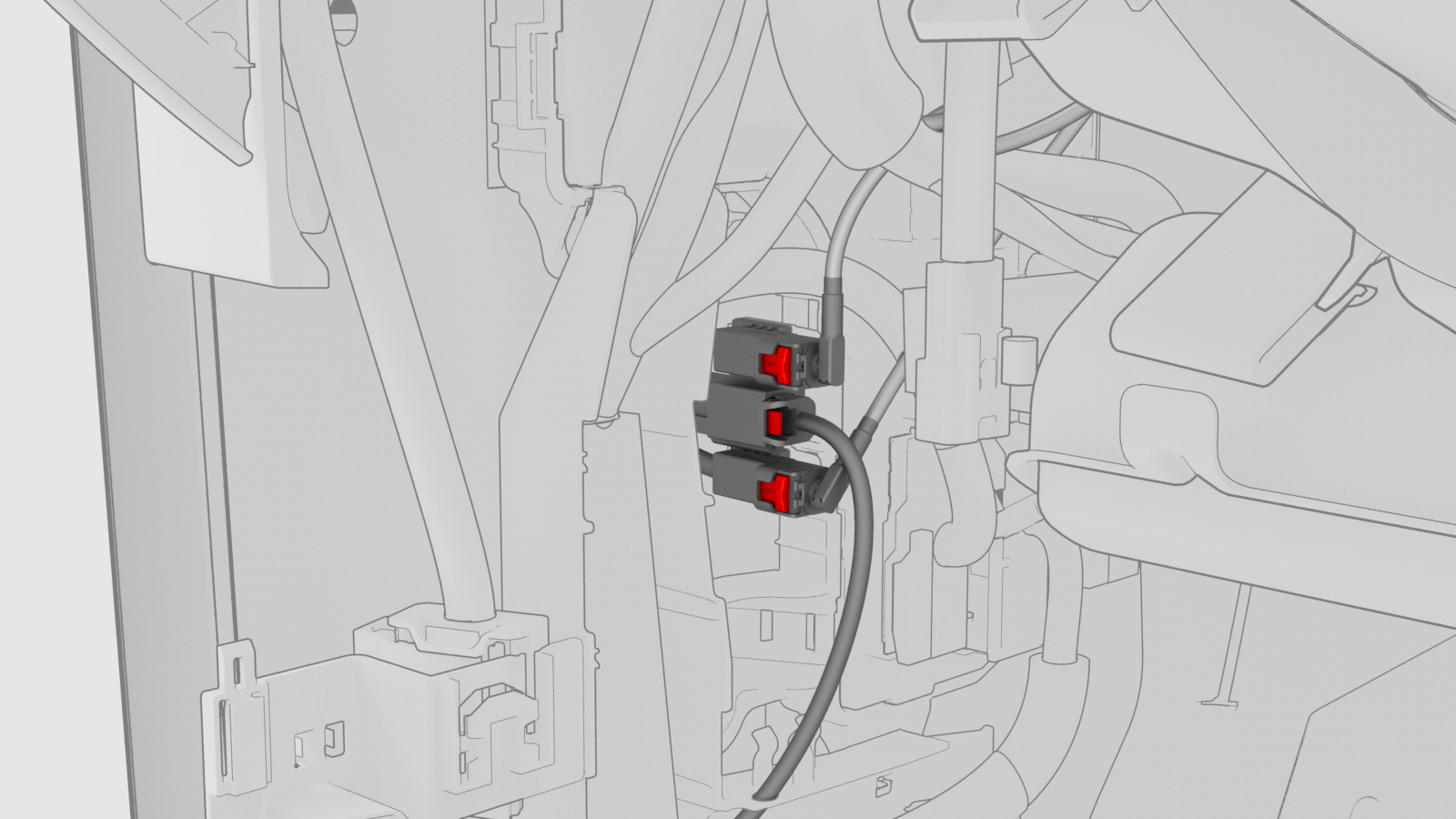
Disconnect the clips that attach the LH front door electrical connectors to the LH body controller module.
-
Release the connector lock, and then remove the electrical connector that attaches the LH front door electrical connector to the LH body controller module.
-
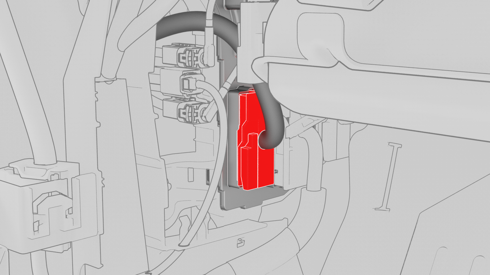
Release the connector lock, and then remove the driver seat electrical connector from the LH body controller module.
-
Release the connector lock, and then remove the instrument panel electrical connector from the LH body controller module.
-
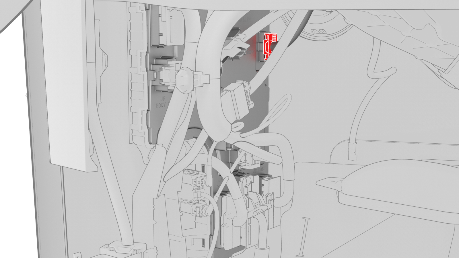
Remove the HVAC electrical connector from the LH body controller module.
-
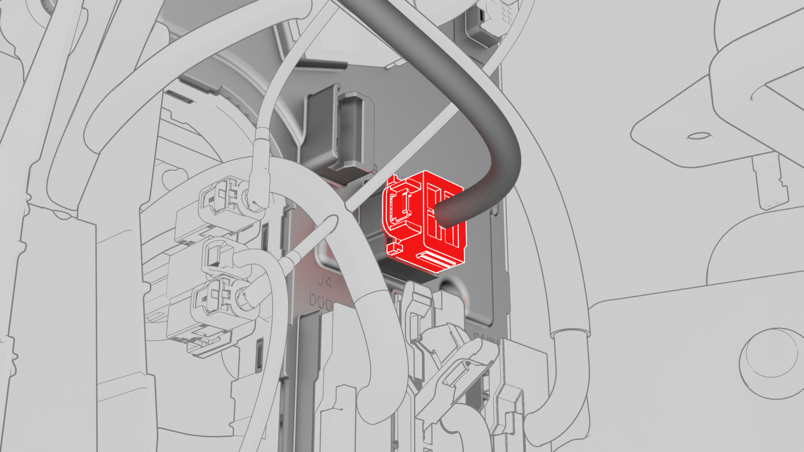
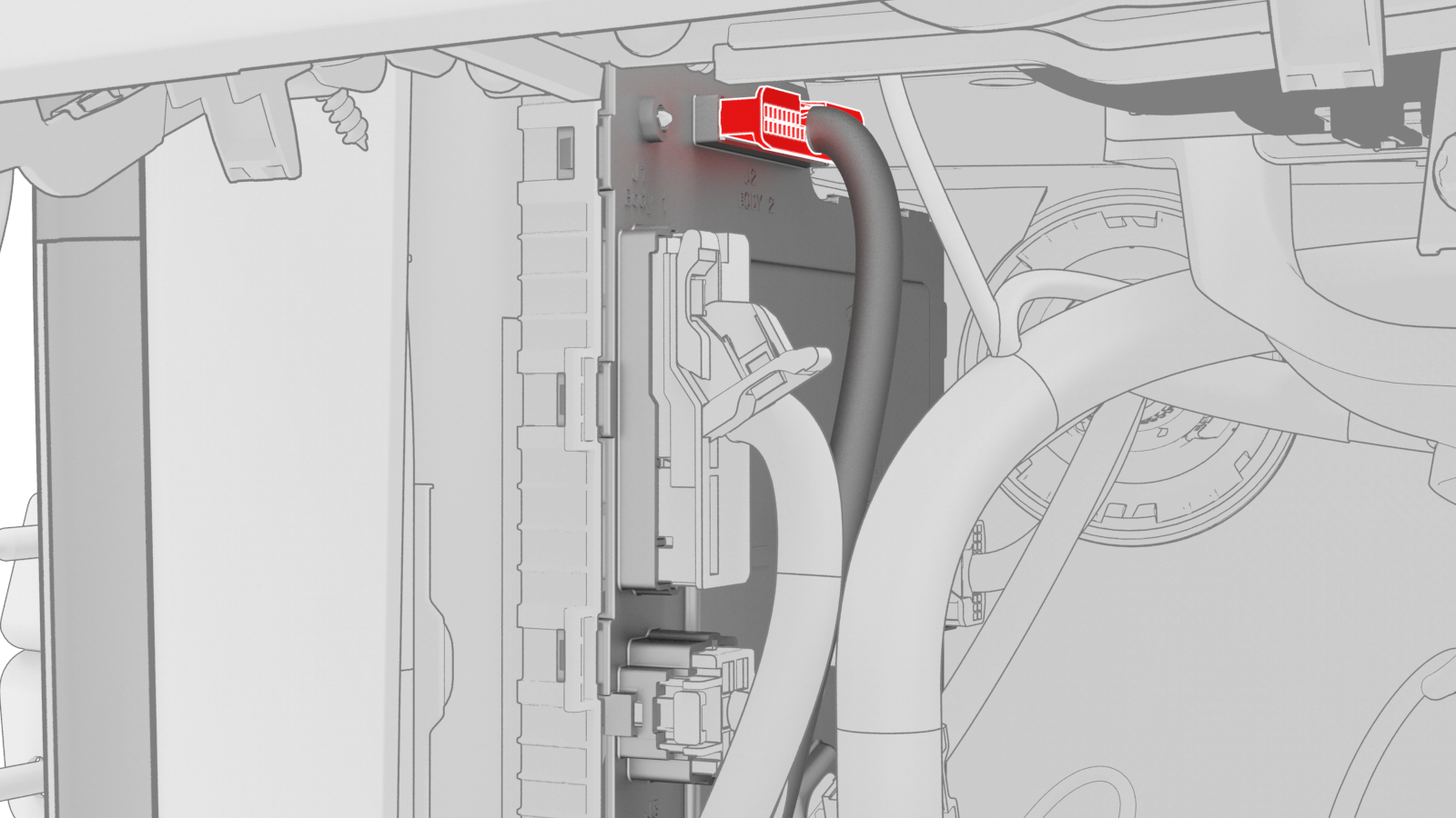
Disconnect the inline electrical harness connector X909 from the LH body harness, and then separate it from the LH body controller module.
-
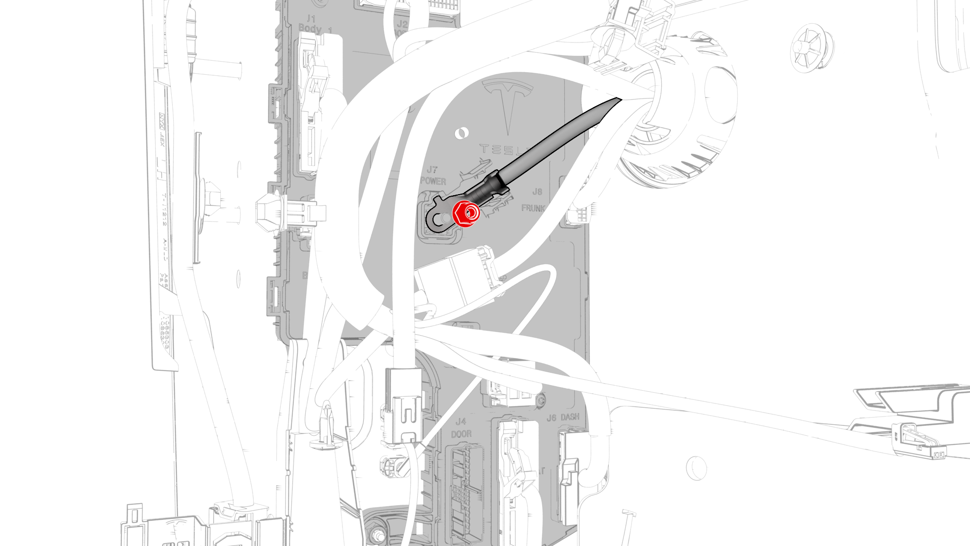
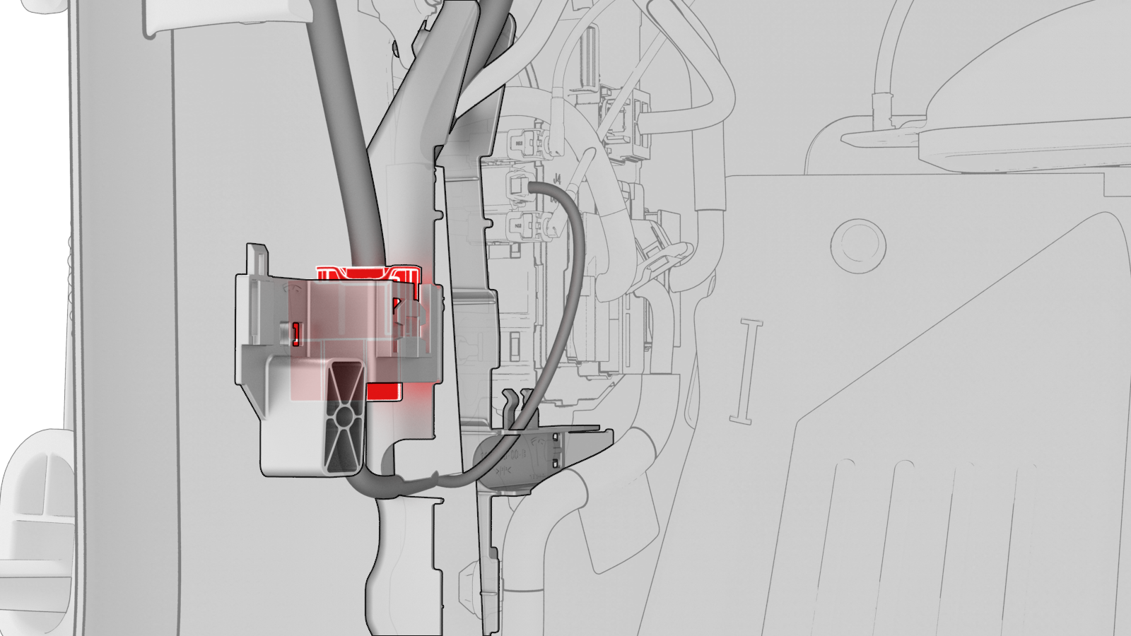
Remove and discard the nut that attaches the 12V power cable to the LH body controller module..
-
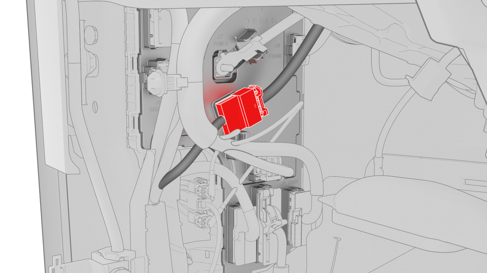
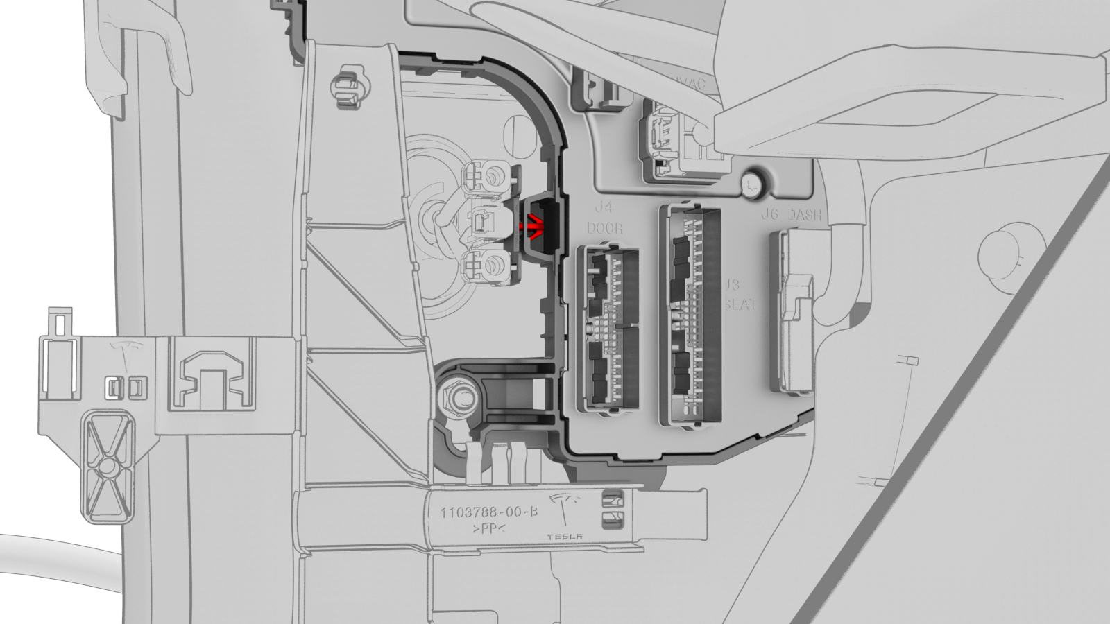
Disconnect the front wiring harness connector from the LH body controller module.
-
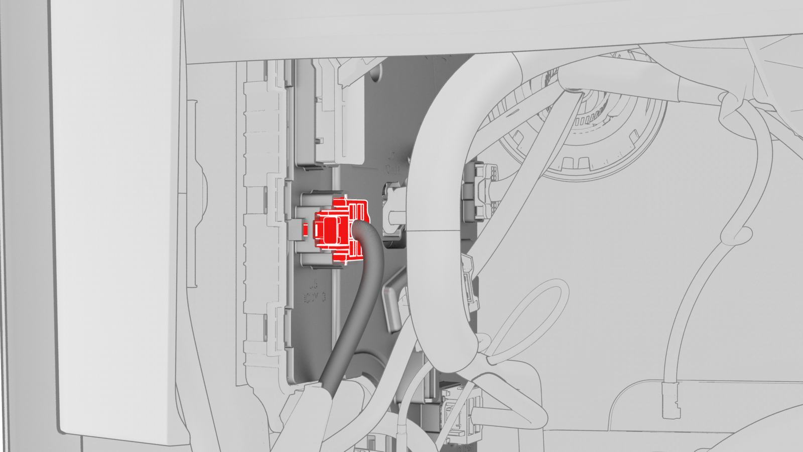
Disconnect the body 3 electrical connector from the LH body controller module.
-
Disconnect the body 1 electrical connector from the LH body controller module.
-
Disconnect the body 2 electrical connector from the LH body controller module.
-
Disconnect the electrical connector from the headliner electrical connector.
-
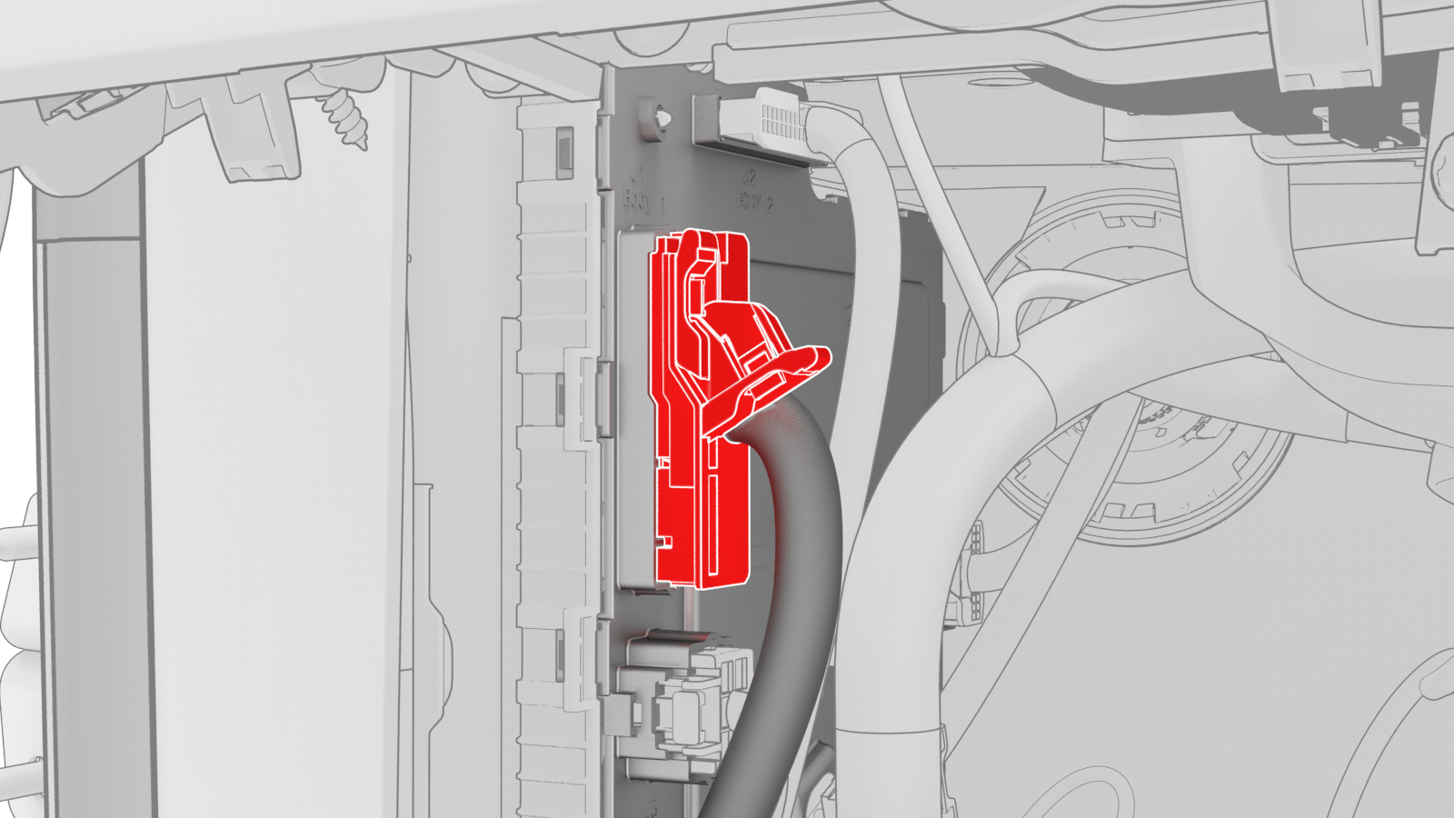
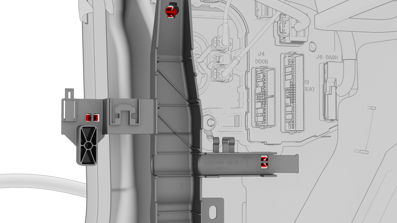
Release the electrical harness clips that attach the LH body controller module to the body.
-
Release the clip that attaches the LH front door electrical harness to the LH body controller module.
-
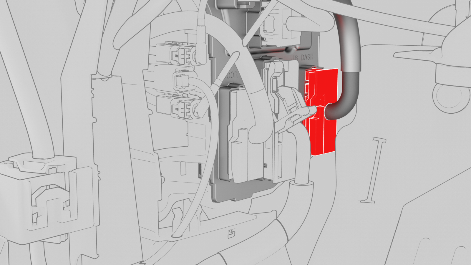
Remove and discard the nut that attaches the LH body controller module to the vehicle.
-
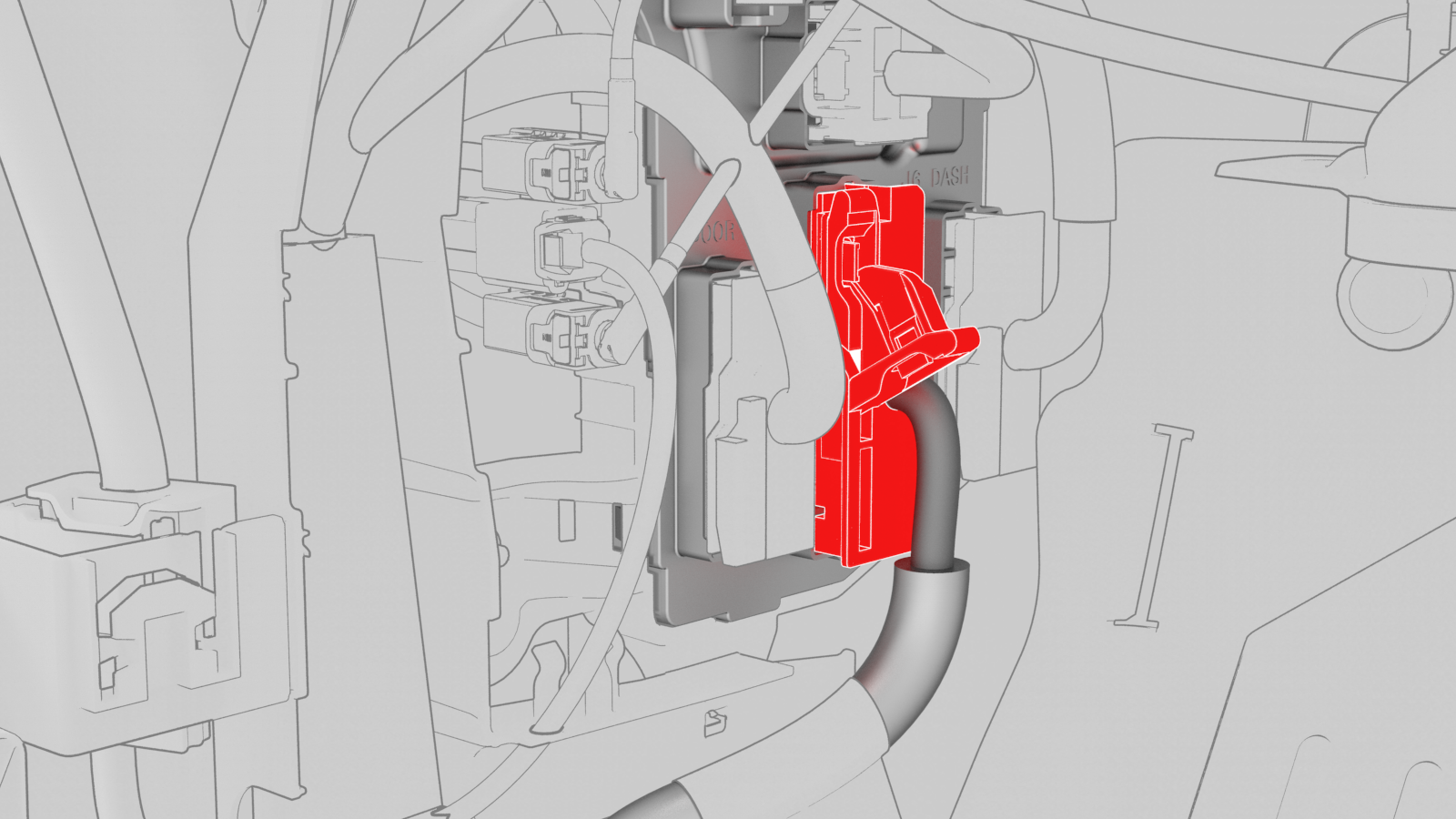
Slide the LH body controller upwards to release the W-clip, and then move the LH body controller module out from underneath the instrument panel.
-
If the LH body controller module has a shroud installed, release the clips that attach the shroud to the module.
| 1 | Remove the 2nd row lower seat cushion. See Seat Cushion - Lower - 2nd Row (Remove and Replace). | ||
| 2 | Remove the rear underhood apron. See Underhood Apron - Rear (Remove and Replace). | ||
| 3 | Disconnect 12V power. See 12V Power (Disconnect and Connect). | ||
| 4 | Remove the LH instrument panel end cap. See End Cap - Instrument Panel - LH (Remove and Replace). | ||
| 5 | Remove the LH middle A-pillar trim. See Trim - A-Pillar - Middle - LH (Remove and Replace). | ||
| 6 | Remove the LH lower A-pillar trim. See Trim - A-Pillar - Lower - LH (Remove and Replace). | ||
| 7 | Remove the driver footwell cover. See Cover - Footwell - Driver (Remove and Replace). | ||
| 8 | Remove the driver knee airbag. See Airbag - Knee - Driver (Remove and Replace). | ||
| 9 | Remove the LH footwell duct. See Duct - Footwell - LH (Remove and Replace). | ||
| 10 | Release the electrical harness clip from the IP carrier. | |
| 11 | Disconnect the clips that attach the LH front door electrical connectors to the LH body controller module. | |
| 12 | Release the connector lock, and then remove the electrical connector that attaches the LH front door electrical connector to the LH body controller module. | |
| 13 | Release the connector lock, and then remove the driver seat electrical connector from the LH body controller module. | |
| 14 | Release the connector lock, and then remove the instrument panel electrical connector from the LH body controller module. | |
| 15 | Remove the HVAC electrical connector from the LH body controller module. | |
| 16 | Disconnect the inline electrical harness connector X909 from the LH body harness, and then separate it from the LH body controller module. | |
| 17 | Remove and discard the nut that attaches the 12V power cable to the LH body controller module.. | |
| 18 | Disconnect the front wiring harness connector from the LH body controller module. | |
| 19 | Disconnect the body 3 electrical connector from the LH body controller module. | |
| 20 | Disconnect the body 1 electrical connector from the LH body controller module. | |
| 21 | Disconnect the body 2 electrical connector from the LH body controller module. | |
| 22 | Disconnect the electrical connector from the headliner electrical connector. | |
| 23 | Release the electrical harness clips that attach the LH body controller module to the body. | |
| 24 | Move the LH body harness away from the LH body controller module. | ||
| 25 | Release the clip that attaches the LH front door electrical harness to the LH body controller module. | |
| 26 | Remove and discard the nut that attaches the LH body controller module to the vehicle. | |
| 27 | Slide the LH body controller upwards to release the W-clip, and then move the LH body controller module out from underneath the instrument panel. | |
| 28 | Remove the LH body controller module from the vehicle. | ||
| 29 | If the LH body controller module has a shroud installed, release the clips that attach the shroud to the module. |
Install
-
Maneuver the LH body controller module into position under the IP carrier. Align the W-clip with the body cutout, and then slide down to attach the LH body controller module to the body.
-
Install new nut that attaches the LH body controller module onto the body.
 Torque 6 Nm
 -
Install the clip that attaches the shroud drain hose to the tab on the LH body controller module.
-
Install the LH front door harness clip to the LH body controller module.
-
Move the LH body harness towards the left side of the LH body controller module, and then attach the harness clips to the LH body controller module.
-
Connect the electrical connector to the headliner electrical connector.
-
Connect the body 2 electrical connector onto the LH body controller module.
-
Connect the body 1 electrical connector onto the LH body controller module.
-
Connect the body 3 electrical connector onto the LH body controller module.
-
Connect the front wiring connector onto the LH body controller module.
-
Install new nut that attaches the 12V power cable to the LH body controller module..Torque 8.5 Nm
-
Connect the inline electrical connector X909 to the LH body harness, and then clip it to the LH body controller module.
-
Install the HVAC electrical connector onto the LH body controller module.
Note: Make sure that the HVAC electrical connector is fully seated, and then engage the connector lock.
-
Install the instrument panel electrical connector onto the LH body controller module.
Note: Make sure that the instrument panel electrical connector is fully seated, and then engage the connector lock.
-
Install the driver seat electrical connector onto the LH body controller module.
Note: Make sure that the driver seat electrical connector is fully seated, and then engage the connector lock.
-
Install the electrical connector that attaches the LH front door electrical connector to the LH body controller module.
Note: Make sure that the LH front door electrical connector is fully seated, and then engage the connector lock.
-
Connect the clips that attach the LH front door electrical connectors to the LH body controller module.
-
Connect the electrical harness clip onto the IP carrier.
| 1 | Install the clip that attach the shroud to the LH body controller module. Note: Make sure that both clips are fully seated so that the edge of the shroud is parallel with the line on the back of the LH body controller module.
| ||
| 2 | Maneuver the LH body controller module into position under the IP carrier. Align the W-clip with the body cutout, and then slide down to attach the LH body controller module to the body. | |
| 3 | Install new nut that attaches the LH body controller module onto the body. Torque 6 Nm | |
| 4 | Install the clip that attaches the shroud drain hose to the tab on the LH body controller module. | |
| 5 | Install the LH front door harness clip to the LH body controller module. | |
| 6 | Move the LH body harness towards the left side of the LH body controller module, and then attach the harness clips to the LH body controller module. | |
| 7 | Connect the electrical connector to the headliner electrical connector. | |
| 8 | Connect the body 2 electrical connector onto the LH body controller module. | |
| 9 | Connect the body 1 electrical connector onto the LH body controller module. | |
| 10 | Connect the body 3 electrical connector onto the LH body controller module. | |
| 11 | Connect the front wiring connector onto the LH body controller module. | |
| 12 | Install new nut that attaches the 12V power cable to the LH body controller module. Torque 8.5 Nm | |
| 13 | Connect the inline electrical connector X909 to the LH body harness, and then clip it to the LH body controller module. | |
| 14 | Install the HVAC electrical connector onto the LH body controller module. Note: Make sure that the HVAC electrical connector is fully seated, and then engage the connector lock.
| |
| 15 | Install the instrument panel electrical connector onto the LH body controller module. Note: Make sure that the instrument panel electrical connector is fully seated, and then engage the connector lock.
| |
| 16 | Install the driver seat electrical connector onto the LH body controller module. Note: Make sure that the driver seat electrical connector is fully seated, and then engage the connector lock.
| |
| 17 | Install the electrical connector that attaches the LH front door electrical connector to the LH body controller module. Note: Make sure that the LH front door electrical connector is fully seated, and then engage the connector lock.
| |
| 18 | Connect the clips that attach the LH front door electrical connectors to the LH body controller module. | |
| 19 | Connect the electrical harness clip onto the IP carrier. | |
| 20 | Install the LH footwell duct. See Duct - Footwell - LH (Remove and Replace). | ||
| 21 | Install the driver knee airbag. See Airbag - Knee - Driver (Remove and Replace). | ||
| 22 | Install the driver footwell cover. See Cover - Footwell - Driver (Remove and Replace). | ||
| 23 | Install the LH lower A-pillar trim. See Trim - A-Pillar - Lower - LH (Remove and Replace). | ||
| 24 | Install the LH middle A-pillar trim. See Trim - A-Pillar - Middle - LH (Remove and Replace). | ||
| 25 | Install the LH instrument panel end cap. See End Cap - Instrument Panel - LH (Remove and Replace). | ||
| 26 | Connect 12V power. See 12V Power (Disconnect and Connect). | ||
| 27 | Install the rear underhood apron. See Underhood Apron - Rear (Remove and Replace). | ||
| 28 | Install the 2nd row lower seat cushion. See Seat Cushion - Lower - 2nd Row (Remove and Replace). | ||
| 29 | Update the vehicle firmware. | ||
| 30 | Connect a laptop with Toolbox to the vehicle. | ||
| 31 | Using Toolbox, type Seat in the search field. Note: Make sure that Actions is selected in Toolbox, if not already.
| ||
| 32 | Using Toolbox, click the play button next to PROC_VCLEFT_SEAT-CALIBRATE, and then select Run. | ||
| 33 | Using Toolbox, type Column in the search field. Note: Make sure that Actions is selected in Toolbox, if not already.
| ||
| 34 | Using Toolbox, click the play button next to PROC-VCLEFT_ X_STEERING-COLUMN-CALIBRATION, and then select Run. | ||
| 35 | Using Toolbox, type Window in the search field. Note: Make sure that Actions is selected in Toolbox, if not already.
| ||
| 36 | Using Toolbox, click the play button next to PROC_VCLEFT-VCRIGHT_ X_WINDOW-CALIBRATION, and then select Run. | ||
| 37 | Disconnect the laptop from the vehicle. |