Passthrough - DCDC - 12V (Remove and Replace)
Correction code 1630600216306002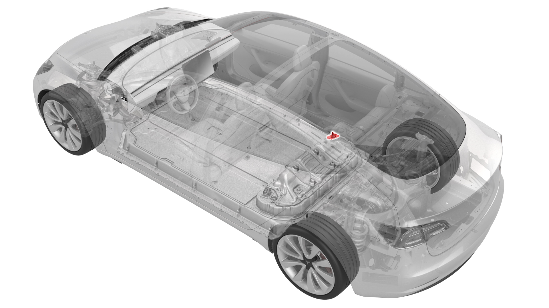
- 1059330-00-BSkt, 1/4in Dr, 5-Lobe Torx Plus External
- 1076927-00-A Resistance meter, microohm, Hioki RM 3548
SPECIAL TOOLS
Skt, 1/4in Dr, 5-Lobe Torx Plus External (1059330-00-B) |
Resistance meter, microohm, Hioki RM 3548 (1076927-00-A) |
Remove
-
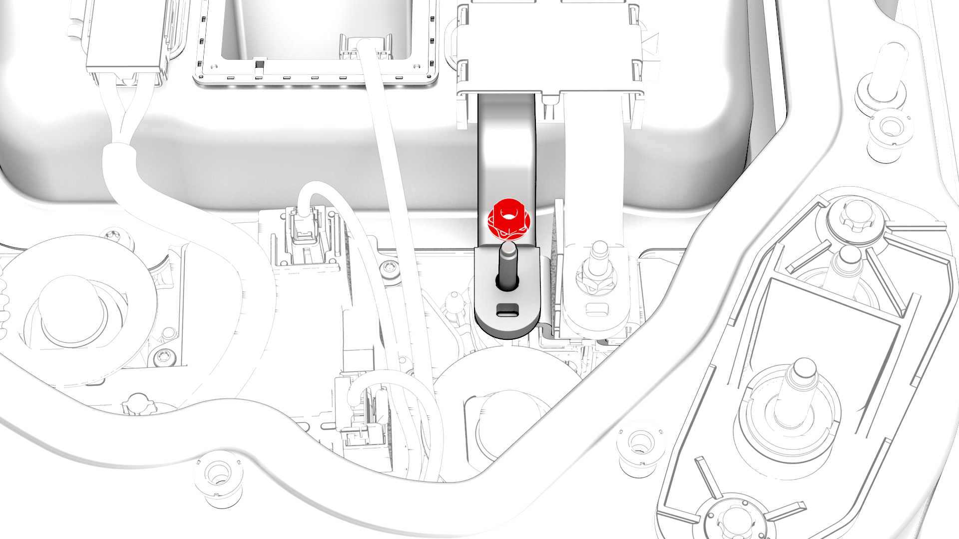
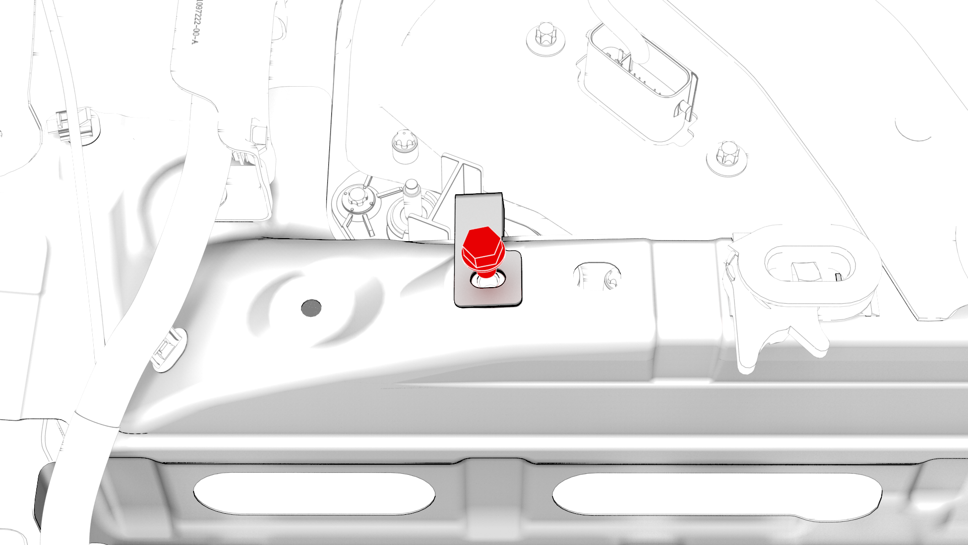
Remove the nut that attaches the positive terminal of the DCDC harness to the positive DCDC passthrough busbar.
-
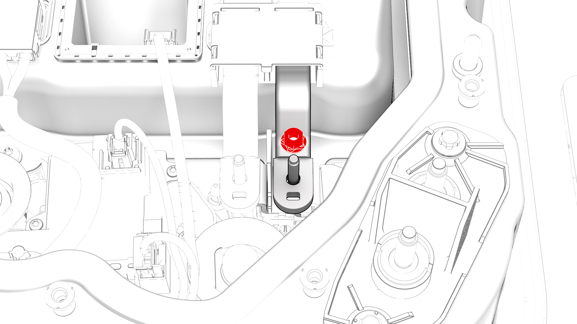
Remove the nut that attaches the negative terminal of the DCDC harness to the negative DCDC passthrough busbar.
-
Release the clip and disconnect the DCDC harness from the power conversion system.
-
Remove the bolts that attaches the DCDC ground busbar to the body.
-
Remove and discard the nut that attaches the DCDC ground busbar to the HV battery, and remove the DCDC ground busbar from the vehicle.
 Torque 15 Nm
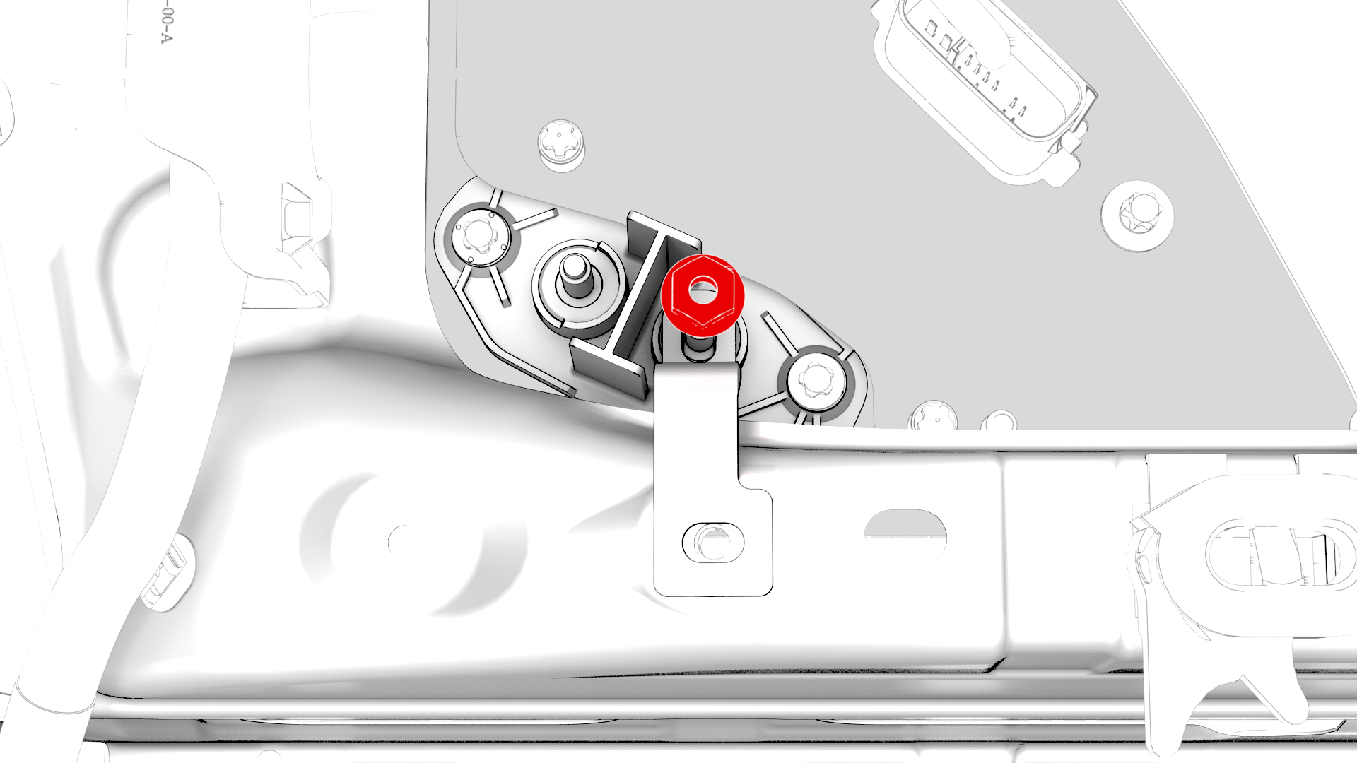
-
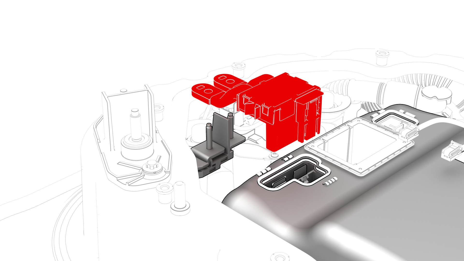
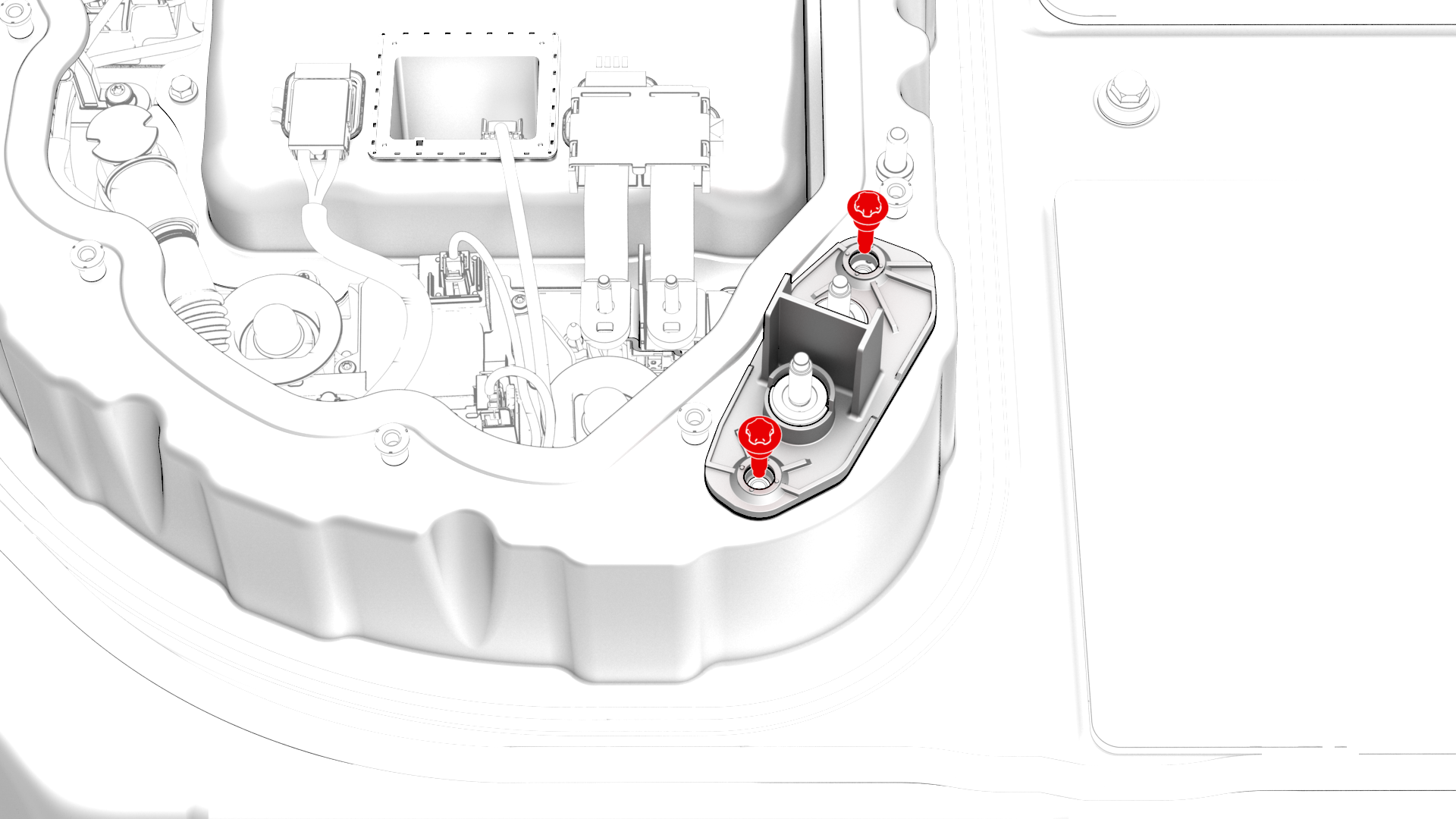
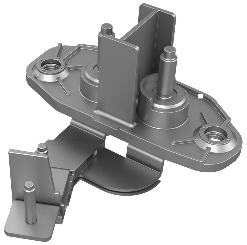
Remove the bolts that attach the 12V DCDC passthrough to the penthouse, and then remove the 12V DCDC passthrough from the penthouse..
| 1 | Remove the high voltage controller. See Controller - High Voltage (Remove and Replace). | ||
| 2 | Remove the nut that attaches the positive terminal of the DCDC harness to the positive DCDC passthrough busbar. | |
| 3 | Remove the nut that attaches the negative terminal of the DCDC harness to the negative DCDC passthrough busbar. | |
| 4 | Release the clip and disconnect the DCDC harness from the power conversion system. | |
| 5 | Remove the bolts that attaches the DCDC ground busbar to the body. | |
| 6 | Remove and discard the nut that attaches the DCDC ground busbar to the HV battery, and remove the DCDC ground busbar from the vehicle. Torque 15 Nm | |
| 7 | Remove the bolts that attach the 12V DCDC passthrough to the penthouse, and then remove the 12V DCDC passthrough from the penthouse.. |
Install
-
Install the 12V DCDC passthrough into the penthouse, install the bolts that attach the 12V DCDC passthrough to the penthouse, and then mark the bolts with a paint pen after they are torqued.
 Torque 10 Nm
 -
Install the bolt that attaches the DCDC ground busbar to the body, and then mark the bolt with a paint pen after it is torqued.
 Torque 20 Nm
 -
Install the DCDC ground busbar to the DCDC passthrough, install a new nut to attach the DCDC ground busbar to the DCDC passthrough, and then mark the nut with a paint pen after it is torqued.Torque 15 Nm
-
Connect the DCDC harness to the power conversion system, and then fasten the clip that attaches the DCDC harness to the power conversion system.
-
Install the nut that attaches the negative terminal of the DCDC harness to the negative DCDC passthrough busbar, and then mark the nut with a paint pen after it is torqued.
 Torque 4.5 Nm
 -
Install the nut that attaches the positive terminal of the DCDC harness to the positive DCDC passthrough busbar, and then mark the nut with a paint pen after it is torqued.Torque 4.5 Nm
-
Use the Hioki resistance meter to measure the resistance between the positive joint of the DCDC harness and the positive terminal of the 12V DCDC passthrough.
Note: The maximum acceptable resistance is 0.100 mΩ (100 μΩ). If the resistance is above this value, escalate a Toolbox session, as appropriate.
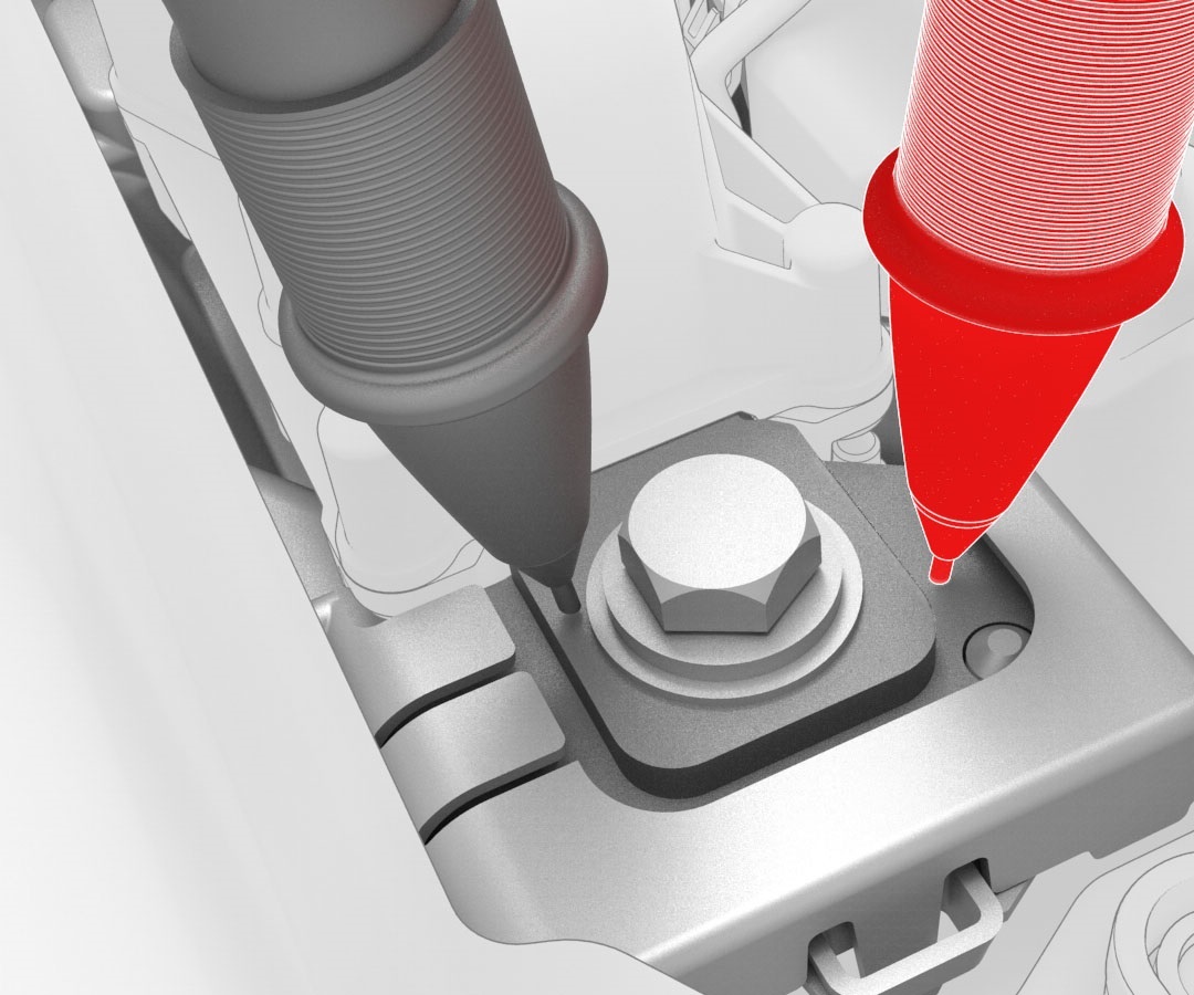 Generic Measurement - Actual busbars and fasteners might appear different
 -
Use the Hioki resistance meter to measure the resistance between the negative joint of the DCDC harness and the negative terminal of the 12V DCDC passthrough.
Note: The maximum acceptable resistance is 0.100 mΩ (100 μΩ). If the resistance is above this value, escalate a Toolbox session, as appropriate.
Generic Measurement - Actual busbars and fasteners might appear different
| 1 | Use an IPA wipe to clean the mating surfaces of the DCDC passthrough, and the DCDC harness. | ||
| 2 | Install the 12V DCDC passthrough into the penthouse, install the bolts that attach the 12V DCDC passthrough to the penthouse, and then mark the bolts with a paint pen after they are torqued. Torque 10 Nm | |
| 3 | Install the bolt that attaches the DCDC ground busbar to the body, and then mark the bolt with a paint pen after it is torqued. Torque 20 Nm | |
| 4 | Install the DCDC ground busbar to the DCDC passthrough, install a new nut to attach the DCDC ground busbar to the DCDC passthrough, and then mark the nut with a paint pen after it is torqued. Torque 15 Nm | |
| 5 | Connect the DCDC harness to the power conversion system, and then fasten the clip that attaches the DCDC harness to the power conversion system. | |
| 6 | Install the nut that attaches the negative terminal of the DCDC harness to the negative DCDC passthrough busbar, and then mark the nut with a paint pen after it is torqued. Torque 4.5 Nm | |
| 7 | Install the nut that attaches the positive terminal of the DCDC harness to the positive DCDC passthrough busbar, and then mark the nut with a paint pen after it is torqued. Torque 4.5 Nm | |
Generic Measurement - Actual busbars and fasteners might appear different
| 8 | Use the Hioki resistance meter to measure the resistance between the positive joint of the DCDC harness and the positive terminal of the 12V DCDC passthrough. Note: The maximum acceptable resistance is 0.100 mΩ (100 μΩ). If the resistance is above this value, escalate a Toolbox session, as appropriate.
| |
Generic Measurement - Actual busbars and fasteners might appear different
| 9 | Use the Hioki resistance meter to measure the resistance between the negative joint of the DCDC harness and the negative terminal of the 12V DCDC passthrough. Note: The maximum acceptable resistance is 0.100 mΩ (100 μΩ). If the resistance is above this value, escalate a Toolbox session, as appropriate.
| |
| 10 | Install the high voltage controller. See Controller - High Voltage (Remove and Replace). | ||
| 11 | Install the pyrotechnic battery disconnect into the penthouse. See Pyrotechnic Battery Disconnect (Remove and Replace). |