Tube - Input - Coolant - Power Conversion System (Remove and Replace)
Correction code 16202002 16202002 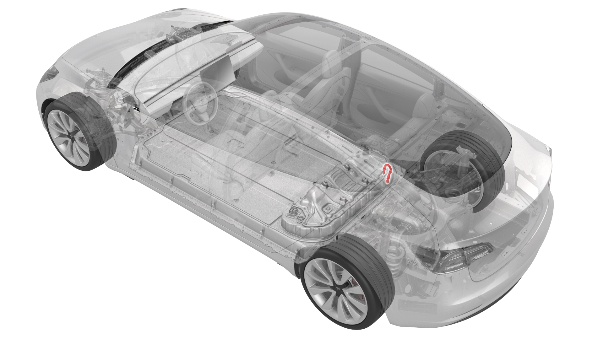
- 1111868-00-B Connector Removal, Coolant, PCS, M3
- 1135762-00-AKit, Svc Plug, Cooling Hose, Model 3
SPECIAL TOOLS
Connector Removal, Coolant, PCS, M3 (1111868-00-B) |
Kit, Svc Plug, Cooling Hose, Model 3 (1135762-00-A) |
 Warning:
Only technicians who have been trained in High Voltage Awareness are permitted to perform this procedure. Proper personal protective equipment (PPE) and insulating HV gloves with a minimum rating of class 0 (1000V) must be worn at all times a high voltage cable, busbar, or fitting is handled. Refer to Tech Note TN-15-92-003, "High Voltage Awareness Care Points" for additional safety information.
Remove
-
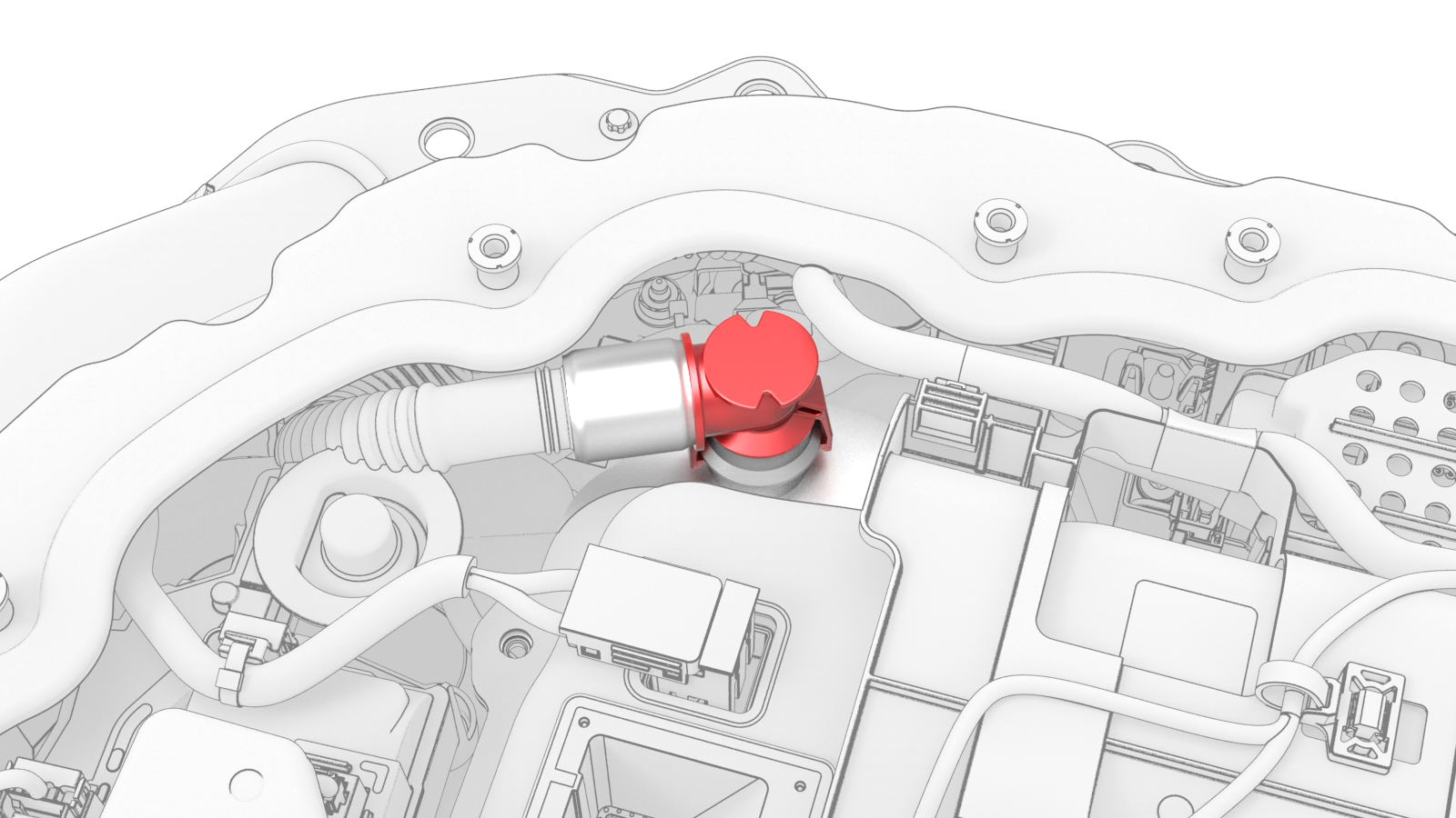
Use the coolant connector removal tool to spread the tube fitting clips wider than the barb on the power conversion system.
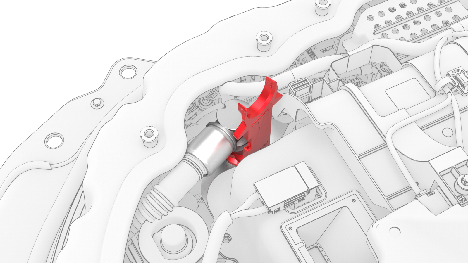 Example of Coolant Connector Removal Tool Use
 -
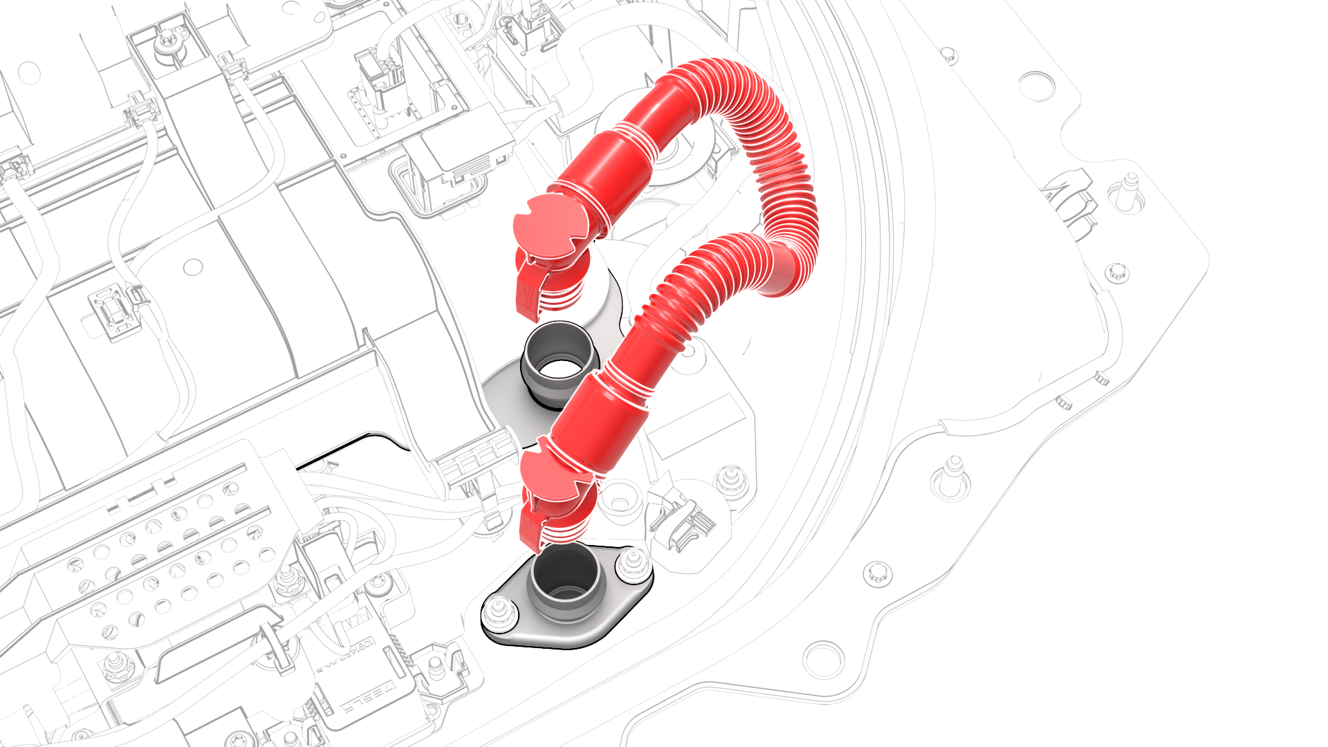
Remove the tube from the vehicle.
-
Wipe up any spilled coolant.
 Caution:Spilled coolant can create an electrical path.
| 1 | Drain the coolant from the power conversion system. See Penthouse Coolant (Drain and Refill). | ||
| 2 | Remove the pyrotechnic battery disconnect from the penthouse. See Pyrotechnic Battery Disconnect (Remove and Replace). | ||
| 3 | Remove the high voltage controller. See Controller - High Voltage (Remove and Replace). | ||
| 4 | Release the clips that attach the harness to the hinge tray and hinges. | ||
| 5 | Raise the hinge tray and remove the hinge tray from the hinges. | ||
| 6 | Cut a slit halfway through 2 absorbent pads and surround each coolant input tube fitting with a pad. | ||
Example of Coolant Connector Removal Tool Use
| 7 | Use the coolant connector removal tool to spread the tube fitting clips wider than the barb on the power conversion system. | |
| 8 | Pull up on the tool and the tube fitting together to disconnect the fitting from the power conversion system. | ||
| 9 | Repeat step 7 and step 8 for the other tube fitting at the battery flange. | ||
| 10 | Remove the tube from the vehicle. | |
| 11 | Install a plugs into the power conversion system and the battery flange. | ||
| 12 | Wipe up any spilled coolant. Caution: Spilled coolant can create an electrical path.
|
Install
-
Wipe up any spilled coolant.
Caution:Spilled coolant can create an electrical path.
-
Make sure that the o-rings are not damaged and that they are properly seated in the connector groove prior to inserting the tube into the power conversion system. Replace components as necessary.
O-rings in good condition
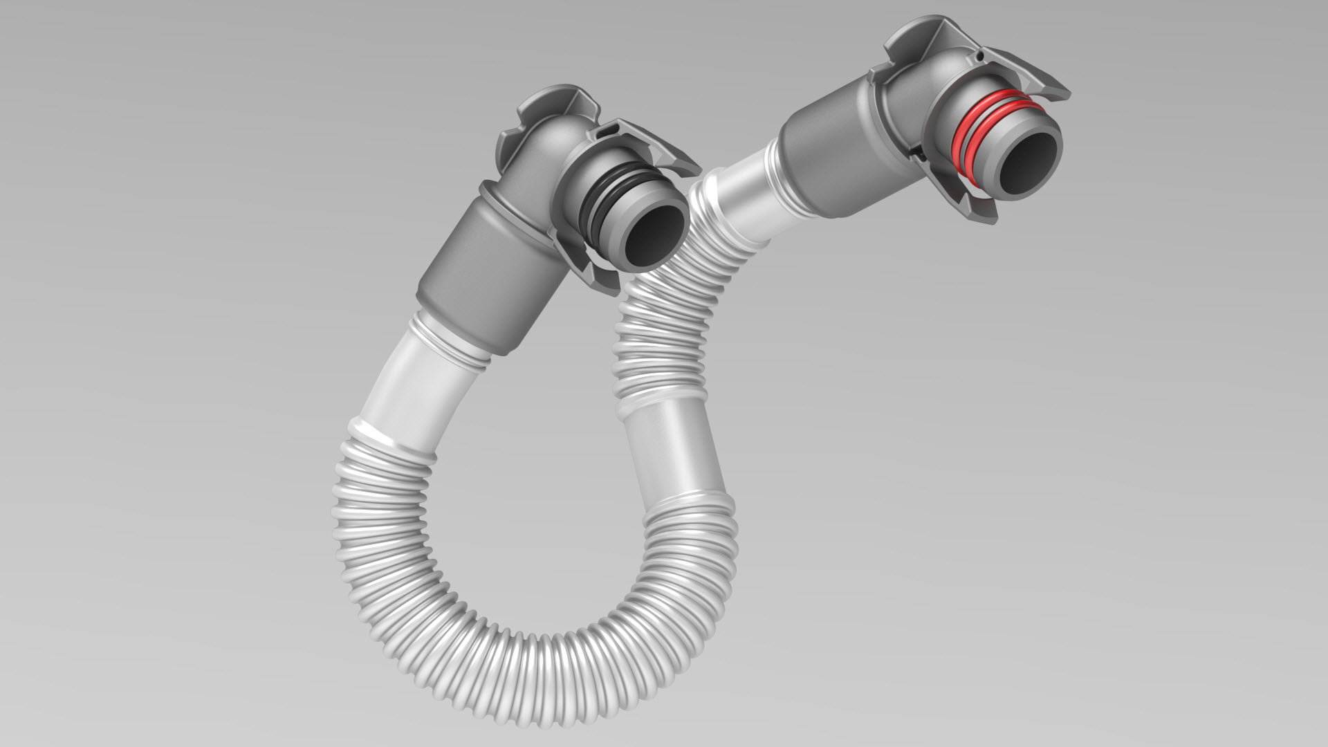
O-ring in poor condition

-
Install the coolant input tube into the power conversion system and the battery flange.
-
Firmly press down on the tube fittings, to make sure that the fittings are securely connected.
Caution:Verify that both clips have fully engaged the barb on the power conversion system and battery flange, and then pull up on the fittings to check retention.
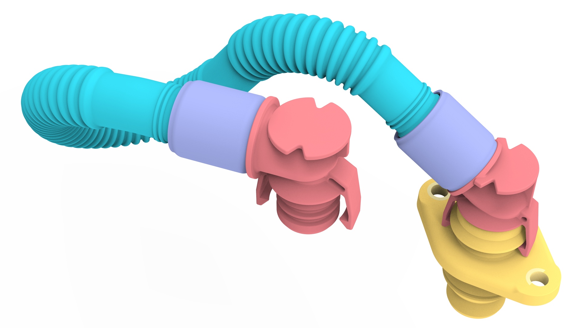
 Example of a Secure Connection
 -
Remove the absorbent pads from around the coolant input tube fittings, and wipe up any spilled coolant.
Caution:Spilled coolant can create an electrical path.
-
Connect the 12V auxiliary battery negative terminal only.
 Torque 6 NmCaution:Do not follow the procedure to connect 12V power at this time.
| 1 | Wipe up any spilled coolant. Caution: Spilled coolant can create an electrical path.
| ||
O-rings in good condition O-ring in poor condition | 2 | Make sure that the o-rings are not damaged and that they are properly seated in the connector groove prior to inserting the tube into the power conversion system. Replace components as necessary. | |
| 3 | Lubricate the coolant input tube o-rings with Silaramic lubricant. | ||
| 4 | Remove the plugs from the power conversion system and the battery flange. | ||
| 5 | Install the coolant input tube into the power conversion system and the battery flange. | |
Example of a Secure Connection
| 6 | Firmly press down on the tube fittings, to make sure that the fittings are securely connected. Caution: Verify that both clips have fully engaged the barb on the power conversion system and battery flange, and then pull up on the fittings to check retention.
| |
| 7 | Remove the absorbent pads from around the coolant input tube fittings, and wipe up any spilled coolant. Caution: Spilled coolant can create an electrical path.
| ||
| 8 | Perform a penthouse coolant leak test. See Penthouse Coolant Leak Test. | ||
| 9 | Connect the 12V auxiliary battery negative terminal only. Torque 6 Nm Caution: Do not follow the procedure to connect 12V power at this time.
| ||
| 10 | Connect a 12V charger to the 12V auxiliary battery terminals. | ||
| 11 | Refill the coolant. See Penthouse Coolant (Drain and Refill). | ||
| 12 | On the touchscreen, touch . | ||
| 13 | Disconnect the 12V charger from the 12V auxiliary battery terminals. | ||
| 14 | Disconnect the 12V auxiliary battery negative terminal. | ||
| 15 | Install the hinge tray into the hinges, and then lower the hinge tray. | ||
| 16 | Fasten the clips that attach the harness to the hinge tray and hinges. | ||
| 17 | Install the high voltage controller. See Controller - High Voltage (Remove and Replace). | ||
| 18 | Install the pyrotechnic battery disconnect into the penthouse. See Pyrotechnic Battery Disconnect (Remove and Replace). |