Contactor - Fast Charge - HV Battery (Remove and Replace)
Correction code 1630260216302602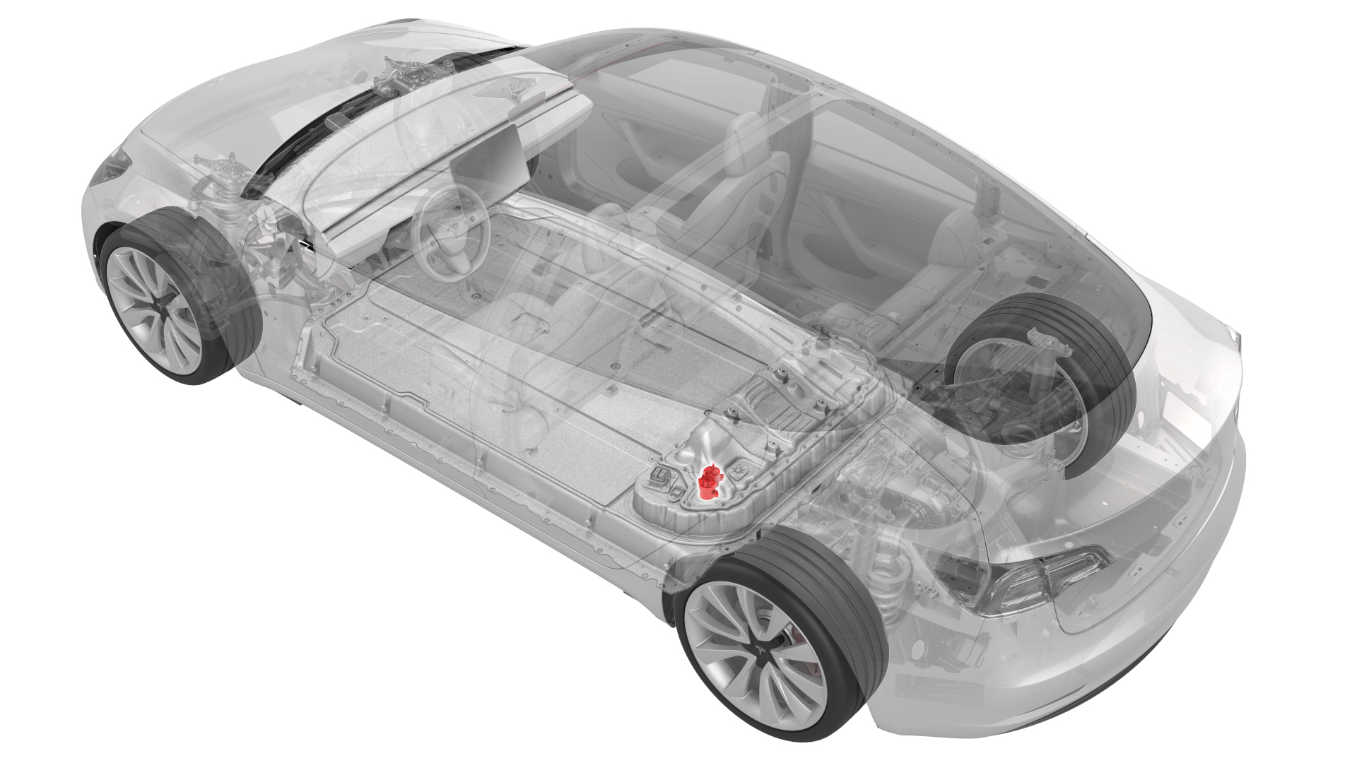
- 1057602-00-ARatchet, 1/4" Sq Dr, HV Insulated
- 1057603-00-AExt Bar, Wobble, 1/4" Dr, HV Insulated
- 1057606-00-ASkt, 1/4" Sq Dr, 13mm, HV Insulated
- 1057607-00-AMagnet, Flexible, HV Insulated, 18"
- 1111868-00-B Connector Removal, Coolant, PCS, M3
- 1135762-00-AKit, Svc Plug, Cooling Hose, Model 3
- 1059330-00-BSkt, 1/4in Dr, 5-Lobe Torx Plus External
- 1076927-00-AResistance meter, microohm, Hioki RM 3548
SPECIAL TOOLS
Ratchet, 1/4" Sq Dr, HV Insulated (1057602-00-A) |
Ext Bar, Wobble, 1/4" Dr, HV Insulated (1057603-00-A) |
Skt, 1/4" Sq Dr, 13mm, HV Insulated (1057606-00-A) |
Magnet, Flexible, HV Insulated, 18" (1057607-00-A) |
Connector Removal, Coolant, PCS, M3 (1111868-00-B) |
Kit, Svc Plug, Cooling Hose, Model 3 (1135762-00-A) |
Skt, 1/4in Dr, 5-Lobe Torx Plus External (1059330-00-B) |
Resistance meter, microohm, Hioki RM 3548 (1076927-00-A) |
 Warning:
Only technicians who have been trained in High Voltage Awareness are permitted to perform this procedure. Proper personal protective equipment (PPE) and insulating HV gloves with a minimum rating of class 0 (1000V) must be worn at all times a high voltage cable, busbar, or fitting is handled. Refer to Tech Note TN-15-92-003, "High Voltage Awareness Care Points" for additional safety information.
Remove
-
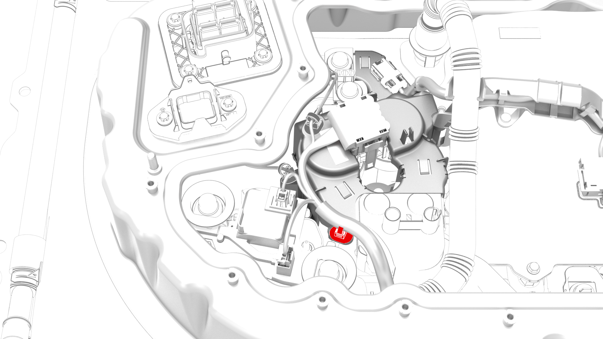
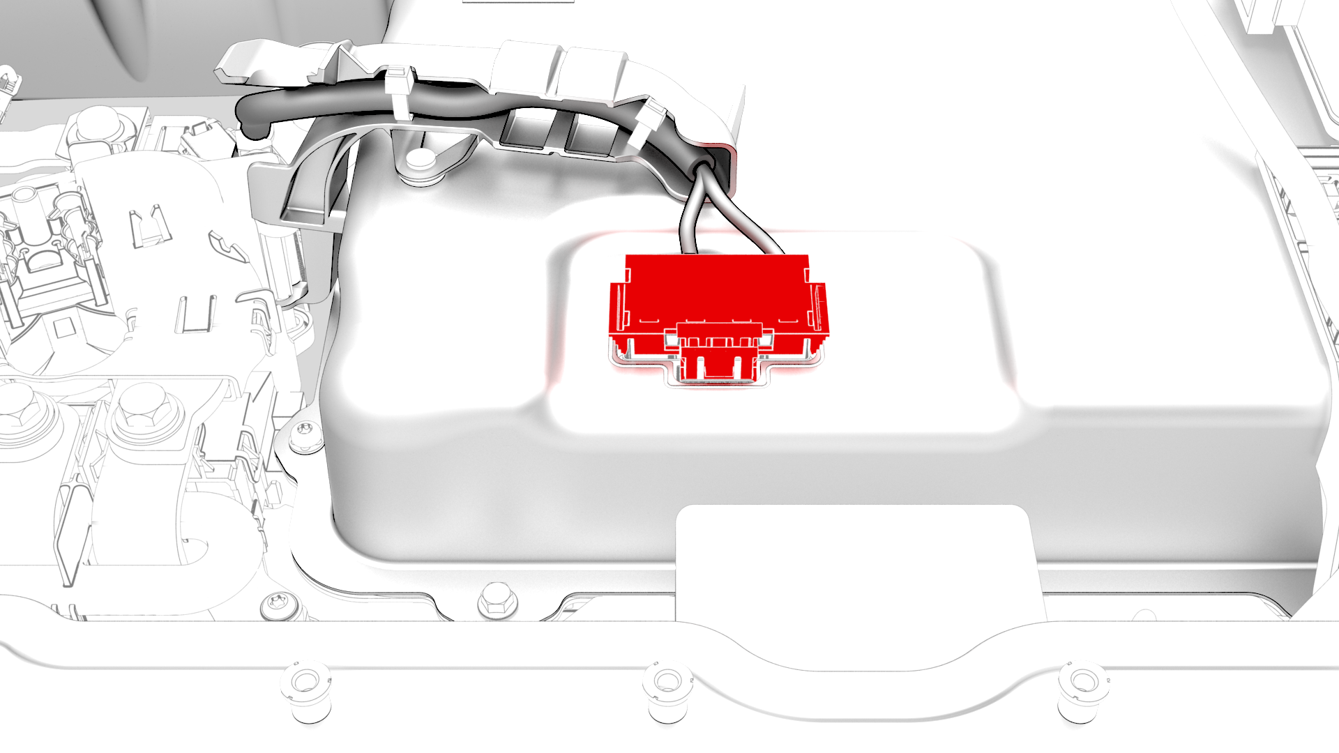
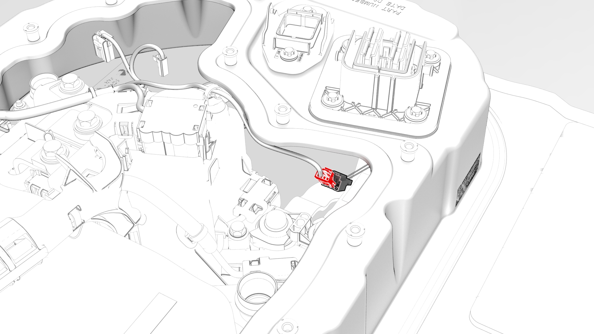
Remove the clip that attaches the HV battery penthouse harness to the HV battery fast charge contactor.
-
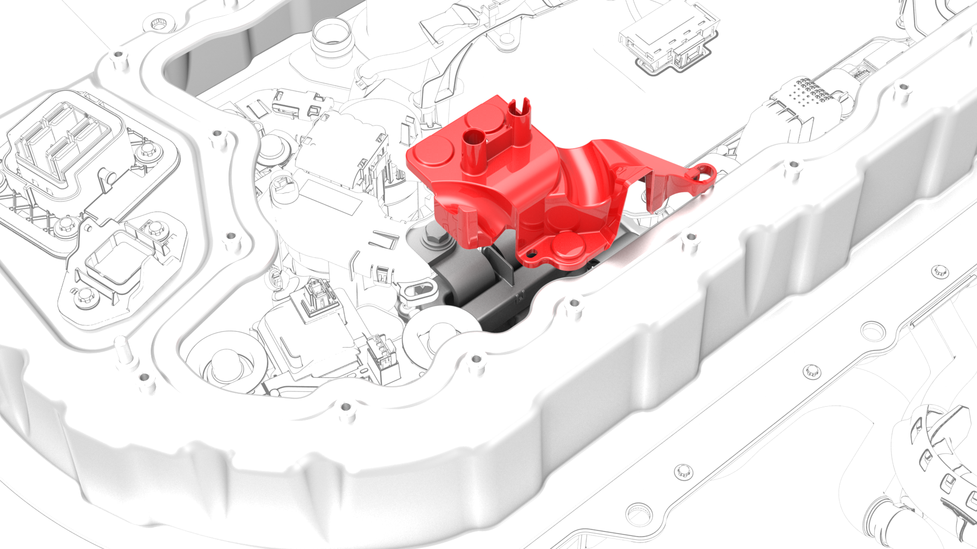
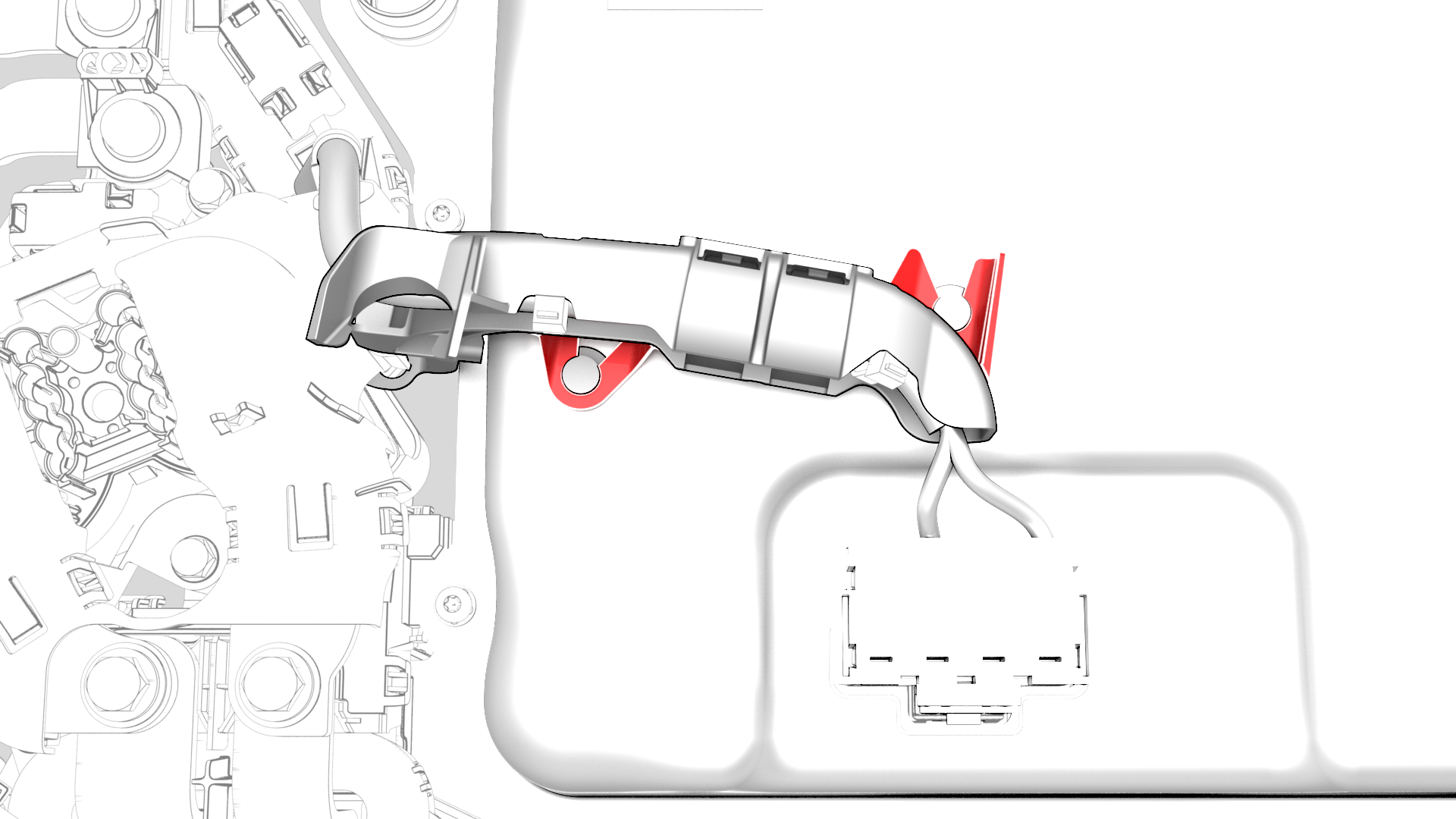
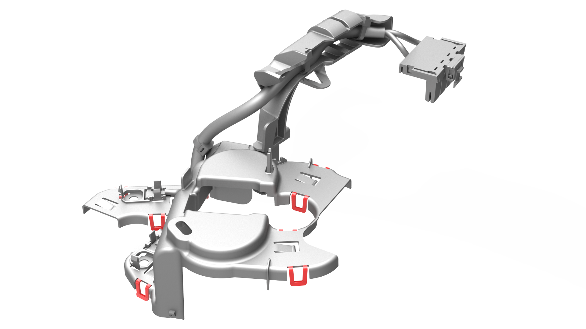
Release the clips that attach the HV battery probing guide to the HV battery and remove the guide from the penthouse.
-
Disconnect the electrical harness from the HV battery fast charge contactor connector.
Note: Squeeze the tabs on either side of the harness connector, to release the tabs from the contactor connector.
 Caution:Do not pry the connectors apart, as this action breaks the tabs and connectors, and necessitates harness replacement.
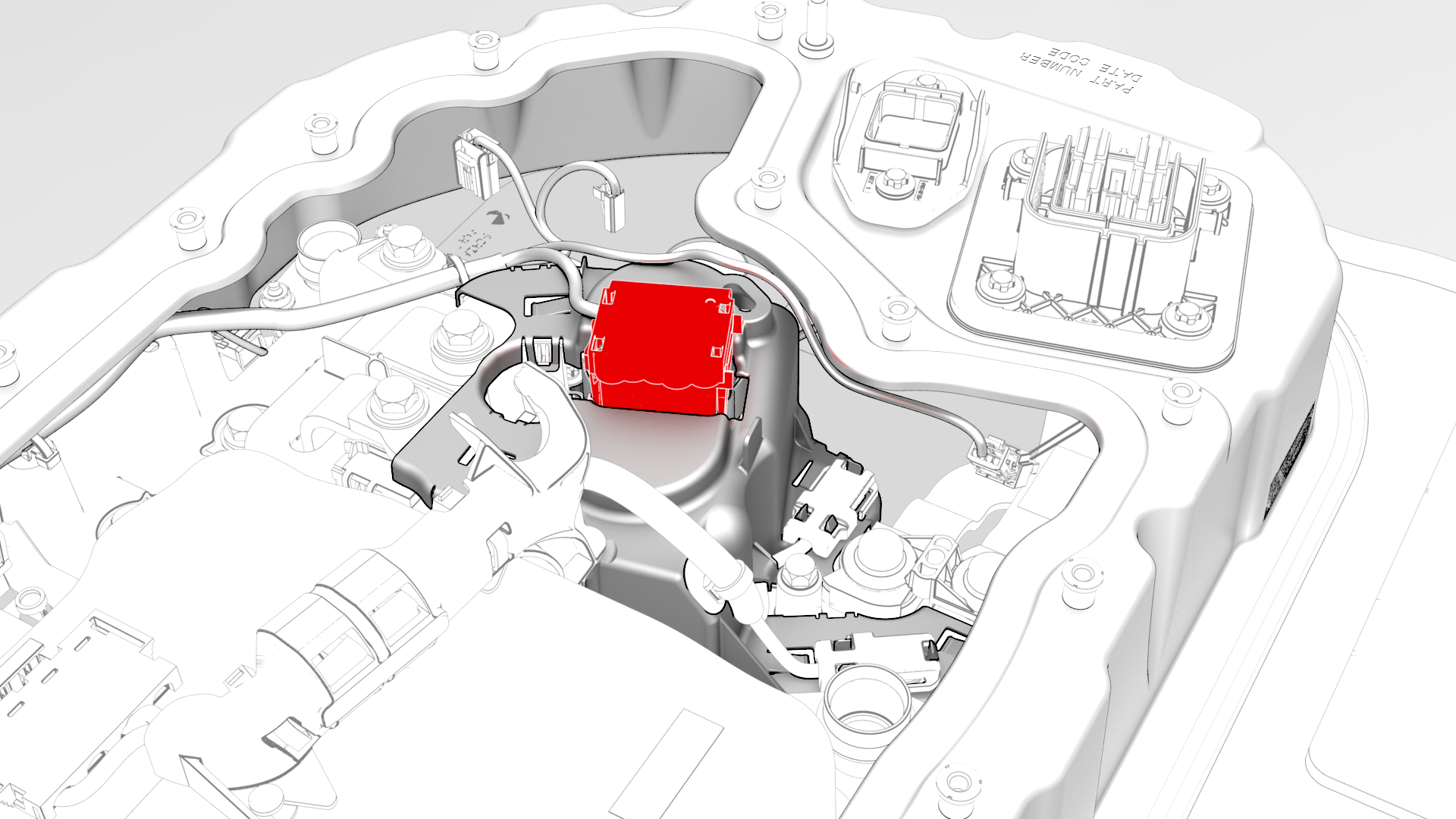
-
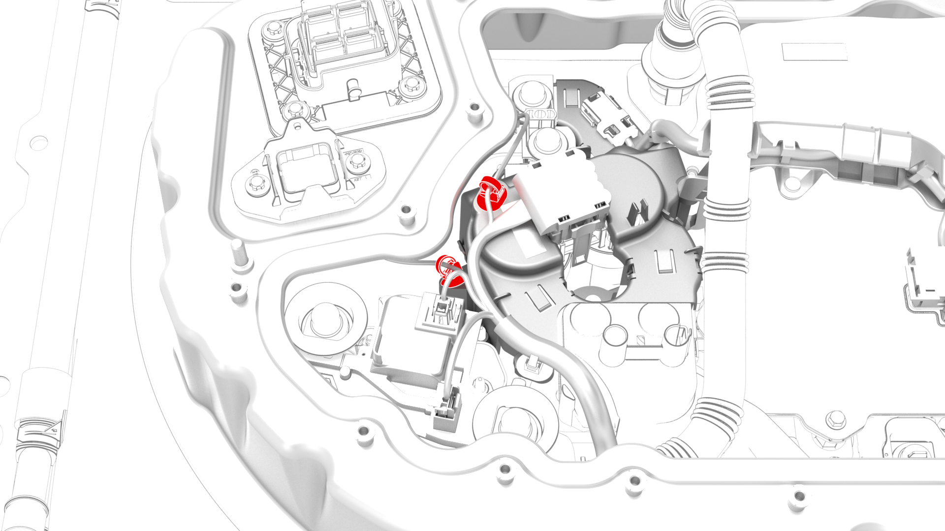
Disconnect the HV battery AC inlet harness from the power conversion system connector.
-
Release the clips that attach the HV battery AC inlet harness cover to the power conversion system.
-
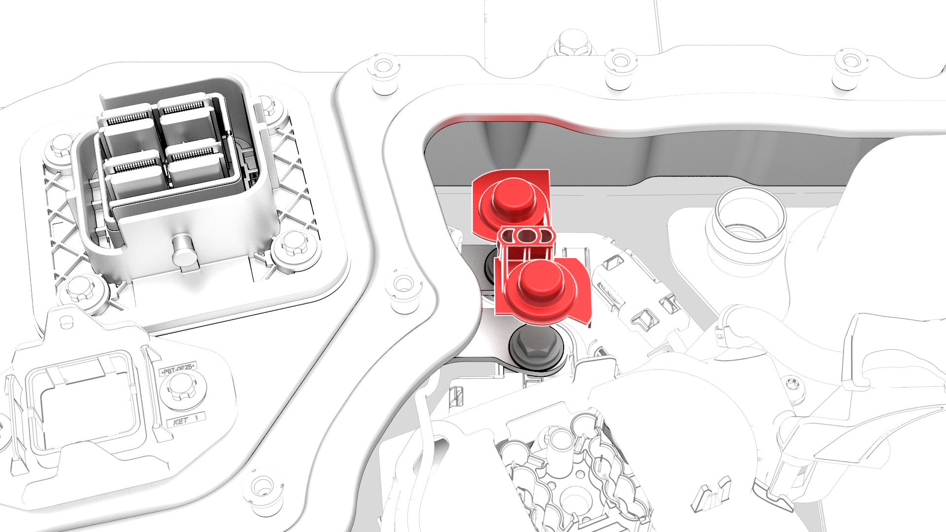
Remove the insulator for the DC input assembly.
-
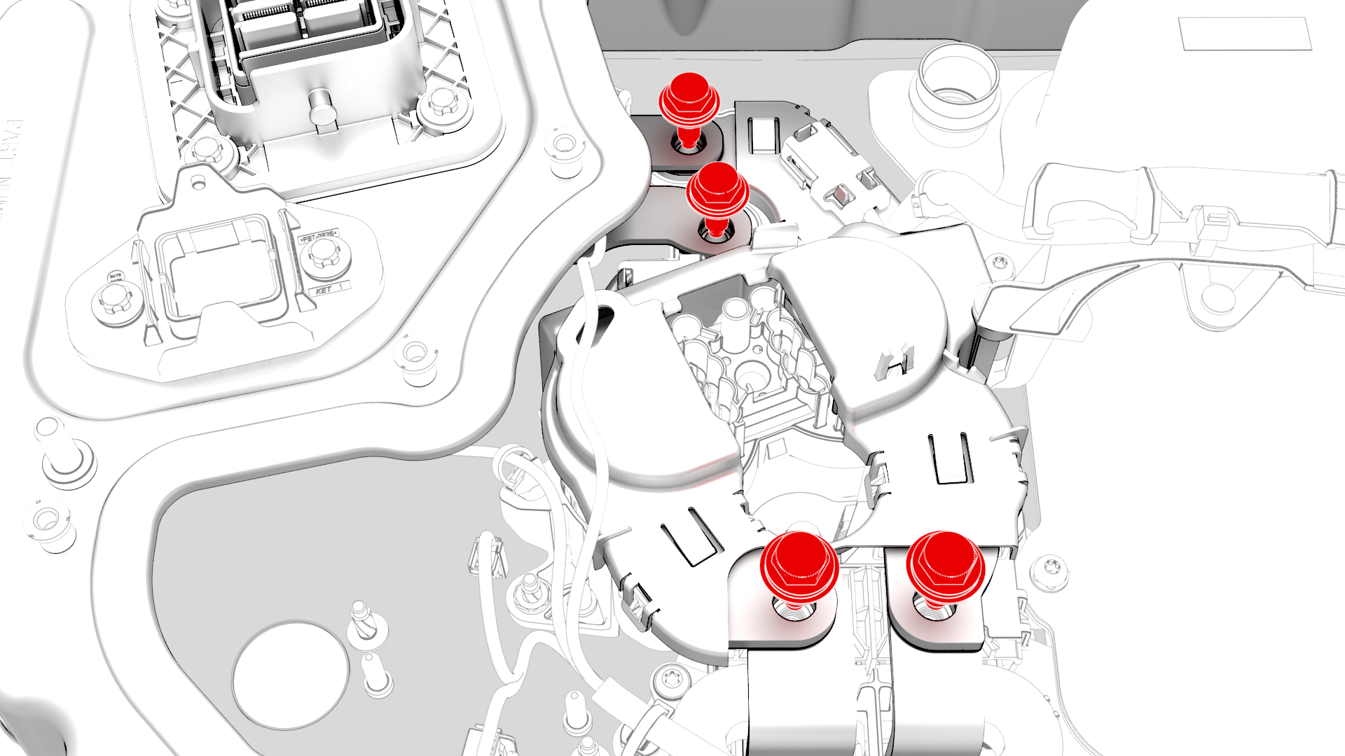
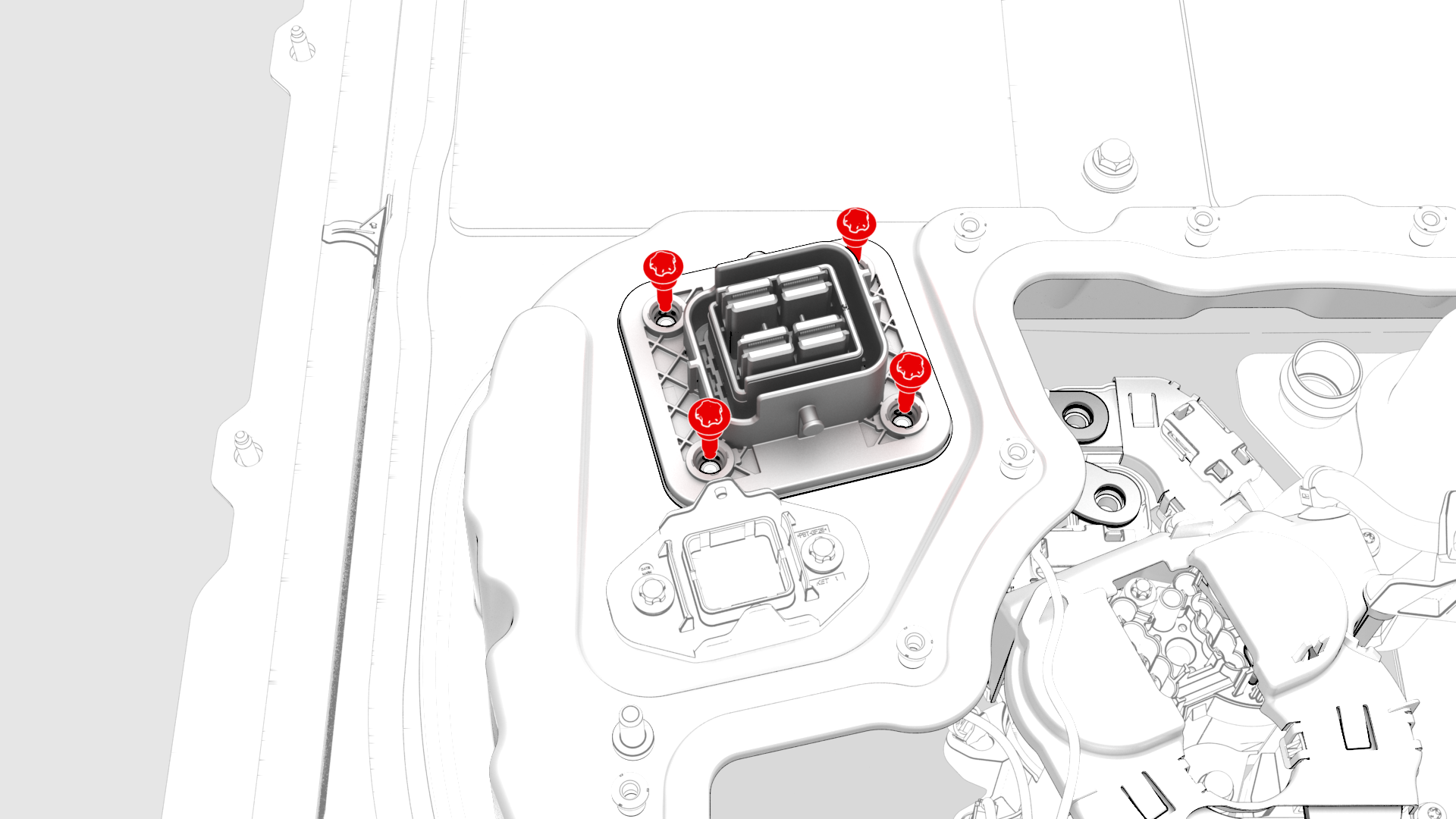
Remove and discard the bolts that attach the negative and positive busbars to the DC links and DC input.
-
Disconnect the electrical harness from the DC input assembly connector.
-
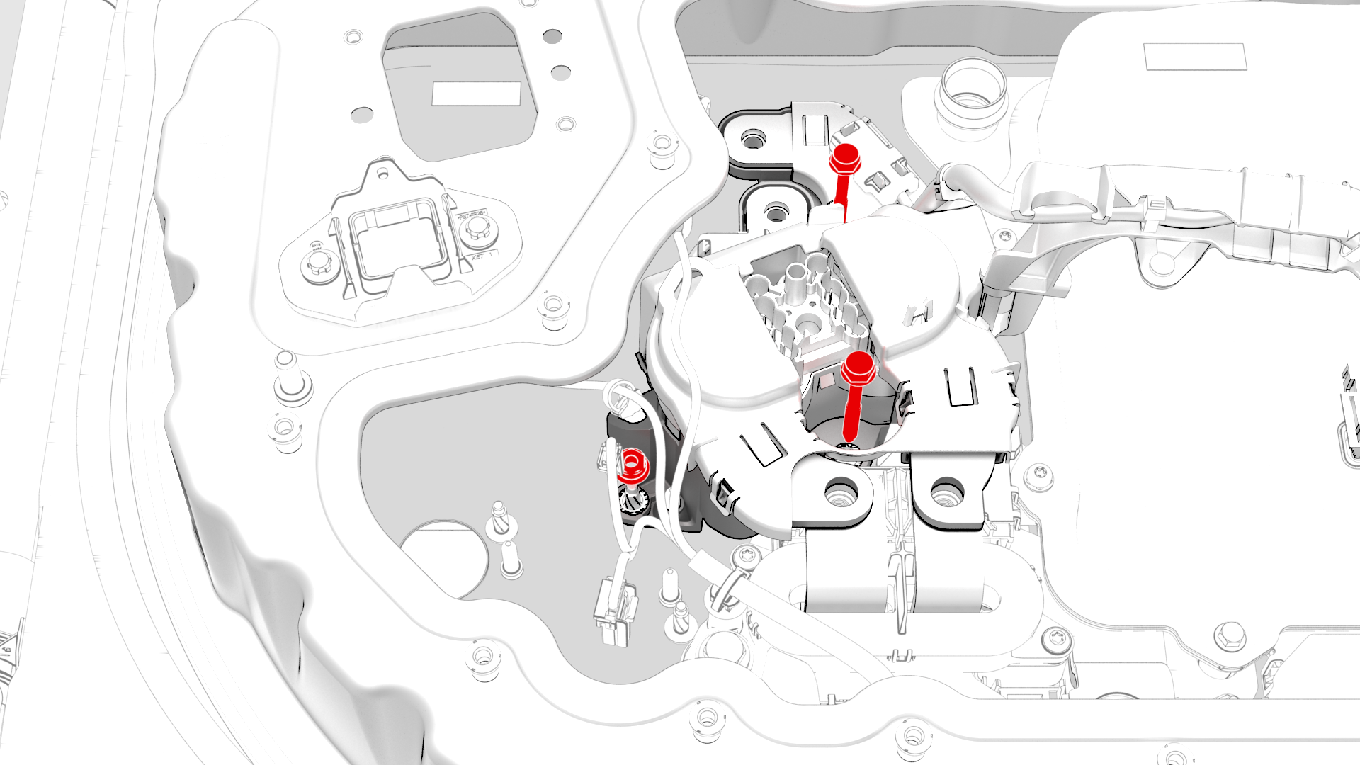
Remove the bolts that attach the DC input assembly to the penthouse, and then remove the DC input assembly from the vehicle.
-
Remove the clips that attach the HV battery penthouse harness to HV battery fast charge contactor cover.
-
Remove the nut and bolts that attach the fast charge contactor to the penthouse, and remove the contactor with the harness from the vehicle.
-
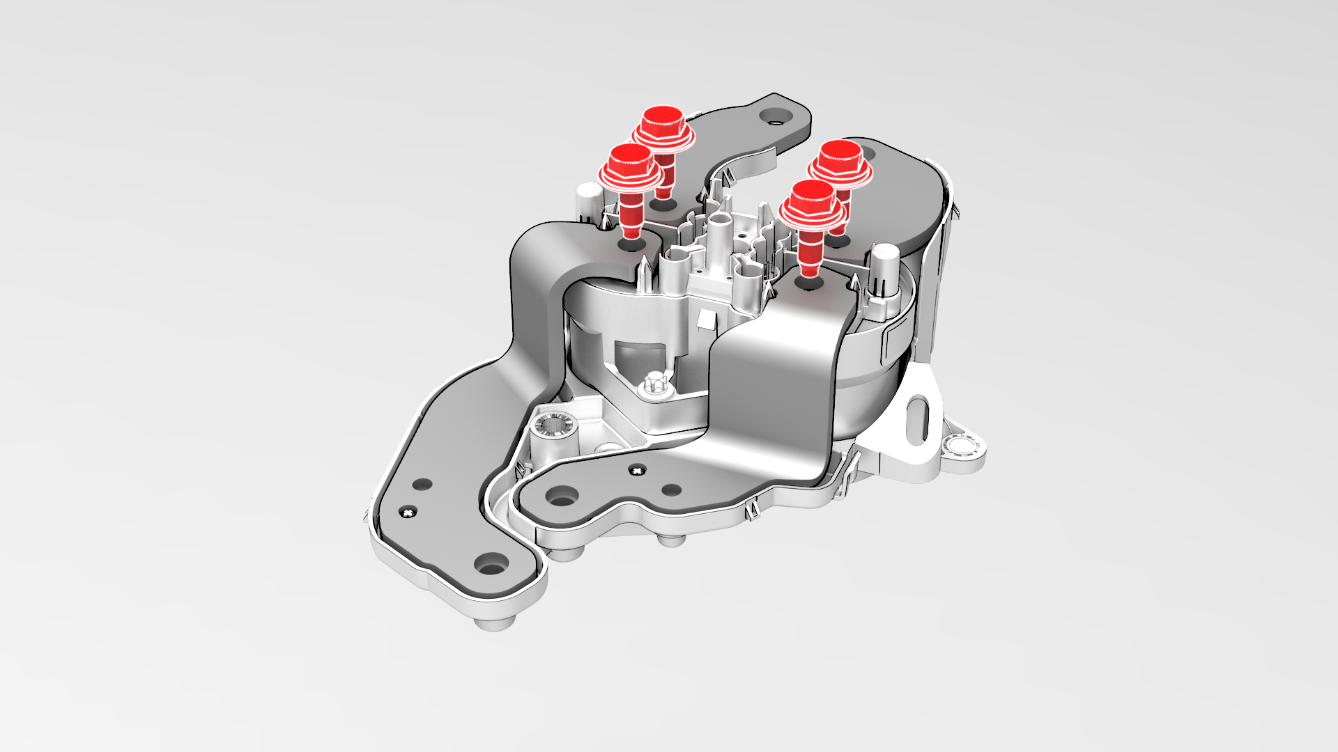
Remove and discard the bolts that attach the busbars to the fast charge contactor, and then remove the busbars from the contactor.
-
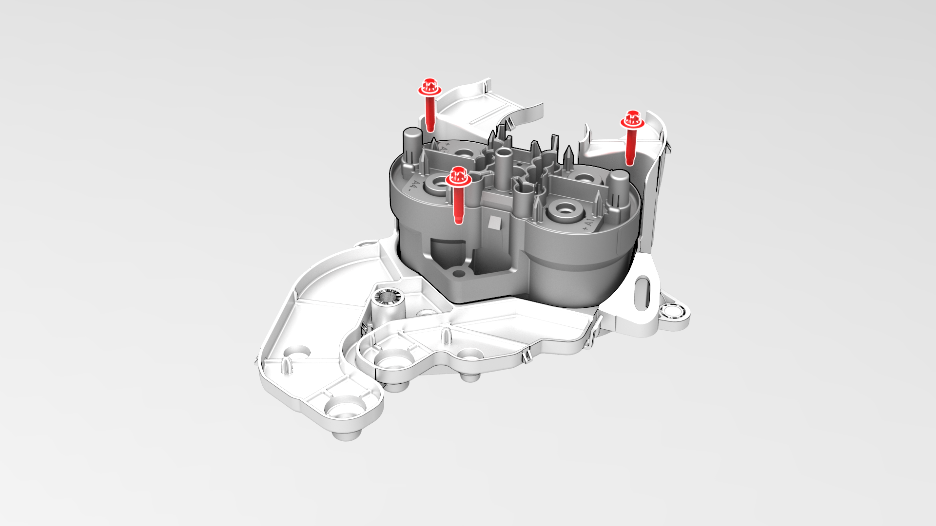
Remove the bolts that attach the fast charge contactor to the insulator, and remove the contactor from the insulator.
| 1 | Drain the coolant from the power conversion system. See Penthouse Coolant (Drain and Refill). | ||
| 2 | Remove the HV battery negative contactor. See Contactor - Negative - HV Battery (Remove and Replace). | ||
| 3 | Remove the power conversion system coolant output tube. See Tube - Output - Coolant - Power Conversion System (Remove and Replace). | ||
| 4 | Remove the clip that attaches the HV battery penthouse harness to the HV battery fast charge contactor. | |
| 5 | Release the clips that attach the HV battery probing guide to the HV battery and remove the guide from the penthouse. | |
| 6 | Disconnect the electrical harness from the HV battery fast charge contactor connector. Note: Squeeze the tabs on either side of the harness connector, to release the tabs from the contactor connector.
Caution: Do not pry the connectors apart, as this action breaks the tabs and connectors, and necessitates harness replacement.
| |
| 7 | Disconnect the HV battery AC inlet harness from the power conversion system connector. | |
| 8 | Release the clips that attach the HV battery AC inlet harness cover to the power conversion system. | |
| 9 | Remove the insulator for the DC input assembly. | |
| 10 | Remove and discard the bolts that attach the negative and positive busbars to the DC links and DC input. | |
| 11 | Disconnect the electrical harness from the DC input assembly connector. | |
| 12 | Remove the bolts that attach the DC input assembly to the penthouse, and then remove the DC input assembly from the vehicle. | |
| 13 | Remove the clips that attach the HV battery penthouse harness to HV battery fast charge contactor cover. | |
| 14 | Remove the nut and bolts that attach the fast charge contactor to the penthouse, and remove the contactor with the harness from the vehicle. | |
| 15 | Remove the HV battery AC inlet harness from the contactor. See Harness - AC Inlet - HV Battery (Remove and Replace). | ||
| 16 | Remove and discard the bolts that attach the busbars to the fast charge contactor, and then remove the busbars from the contactor. | |
| 17 | Remove the bolts that attach the fast charge contactor to the insulator, and remove the contactor from the insulator. |
Install
-
Install the bolts that attach the fast charge contactor to the insulator, and then mark the bolts with a paint pen after they are torqued.
 Torque 5.5 Nm
 -
Install the positive and negative inlet and DC link busbars to the fast charge contactor, install the new bolts (x4) that attach the busbars to the contactor, and then mark the bolts with a paint pen after they are torqued.
 Torque 9 Nm
 -
Use the Hioki resistance meter to measure the resistance between the positive (LH) HV joint bolt head of the fast charge contactor and the respective positive (LH) inlet busbar, and then the resistance between the positive (LH) HV joint bolt head of the fast charge contactor and the respective positive (LH) DC link busbar.
Note: The maximum acceptable resistance is 0.030 mΩ (30 μΩ) per joint. If the resistance is above this value, escalate a Toolbox session, as appropriate.
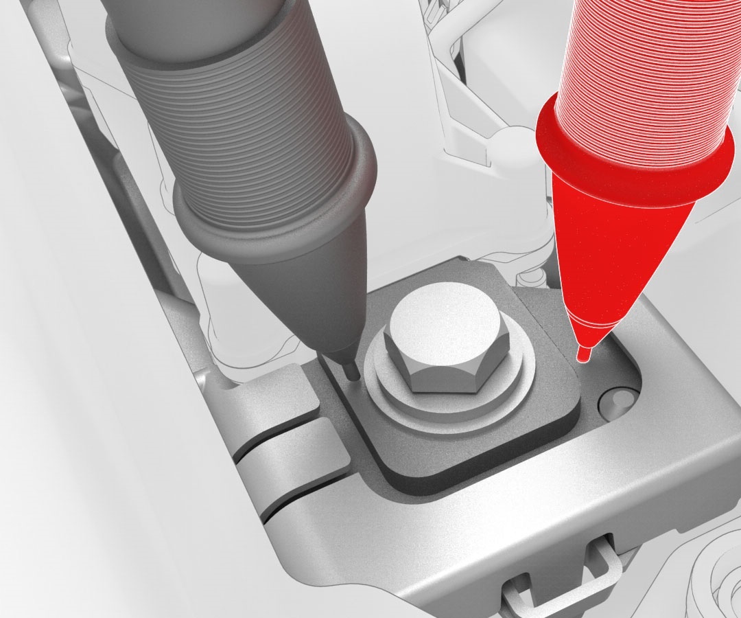 Generic Measurement - Actual busbars and fasteners might appear different
 -
Use the Hioki resistance meter to measure the resistance between the negative (RH) HV joint bolt head of the fast charge contactor and the respective negative (RH) inlet busbar, and then the resistance between the negative (RH) HV joint bolt head of the fast charge contactor and the respective negative (RH) DC link busbar.
Note: The maximum acceptable resistance is 0.040 mΩ (40 μΩ) per joint. If the resistance is above this value, escalate a Toolbox session, as appropriate.
Generic Measurement - Actual busbars and fasteners might appear different
-
Install a new HV battery AC inlet harness to the fast charge contactor. See Harness - AC Inlet - HV Battery (Remove and Replace).
Note: The AC inlet harness is a one time use.
-
Install the bolts and nut that attach the fast charge assembly to the penthouse, and then mark the bolts and nut with a paint pen after they are torqued.
 Torque 5.5 Nm
 Torque 8 Nm
 -
Install the clips that attach the HV battery penthouse harness to HV battery fast charge contactor cover.
-
Install the DC input assembly to the penthouse, install the bolts (x4) that attach the DC input assembly to the penthouse, and then mark the bolts with a paint pen after they are torqued..
 Torque 6 Nm
 -
Connect the electrical harness to the DC input assembly connector.
-
Install new bolts (x4) to attach the negative and positive busbars to the DC links and DC input, and then mark the bolts with a paint pen after they are torqued.Torque 9 Nm
-
Use the Hioki resistance meter to measure the resistance at the HV joint between the positive DC input busbar and the positive (LH) fast charge contactor busbar.
Note: The maximum acceptable resistance is 0.060 mΩ (60 μΩ). If the resistance is above this value, escalate a Toolbox session, as appropriate.
Generic Measurement - Actual busbars and fasteners might appear different
-
Use the Hioki resistance meter to measure the resistance at the HV joint between the positive (LH) DC link busbar and the positive (LH) fast charge contactor busbar.
Note: The maximum acceptable resistance is 0.040 mΩ (40 μΩ). If the resistance is above this value, escalate a Toolbox session, as appropriate.
Generic Measurement - Actual busbars and fasteners might appear different
-
Use the Hioki resistance meter to measure the resistance at the HV joint between the negative DC input busbar and the negative (RH) fast charge contactor busbar.
Note: The maximum acceptable resistance is 0.060 mΩ (60 μΩ). If the resistance is above this value, escalate a Toolbox session, as appropriate.
Generic Measurement - Actual busbars and fasteners might appear different
-
Use the Hioki resistance meter to measure the resistance at the HV joint between the negative (RH) DC link busbar and the negative (RH) fast charge contactor busbar.
Note: The maximum acceptable resistance is 0.060 mΩ (60 μΩ). If the resistance is above this value, escalate a Toolbox session, as appropriate.
Generic Measurement - Actual busbars and fasteners might appear different
-
Install the insulator for the DC input assembly.
-
Fasten the clips that attach the HV battery AC inlet harness cover to the power conversion system.
-
Connect the HV battery AC inlet harness to the power conversion system connector.
-
Connect the electrical harness to the HV battery fast charge contactor connector.
-
Install the HV battery probing guide into the penthouse, and then fasten the clips that attach the guide to the HV battery.
-
Install the clip that attaches the HV battery penthouse harness to the HV battery fast charge contactor.
-
Install the power conversion system coolant output tube. See Tube - Output - Coolant - Power Conversion System (Remove and Replace).
Caution:Make sure that the coolant output tube is securely connected by firmly pressing down on the fittings, verify that both clips have fully engaged the barb on the power conversion system and battery flange, and then pull up on the fittings to check retention.
-
Connect the 12V auxiliary battery negative terminal only.
 Torque 6 NmCaution:Do not follow the procedure to connect 12V power at this time.
| 1 | Use IPA wipes to clean the high voltage mating surfaces of the fast charge contactor and the positive and negative DC link and DC input busbars. | ||
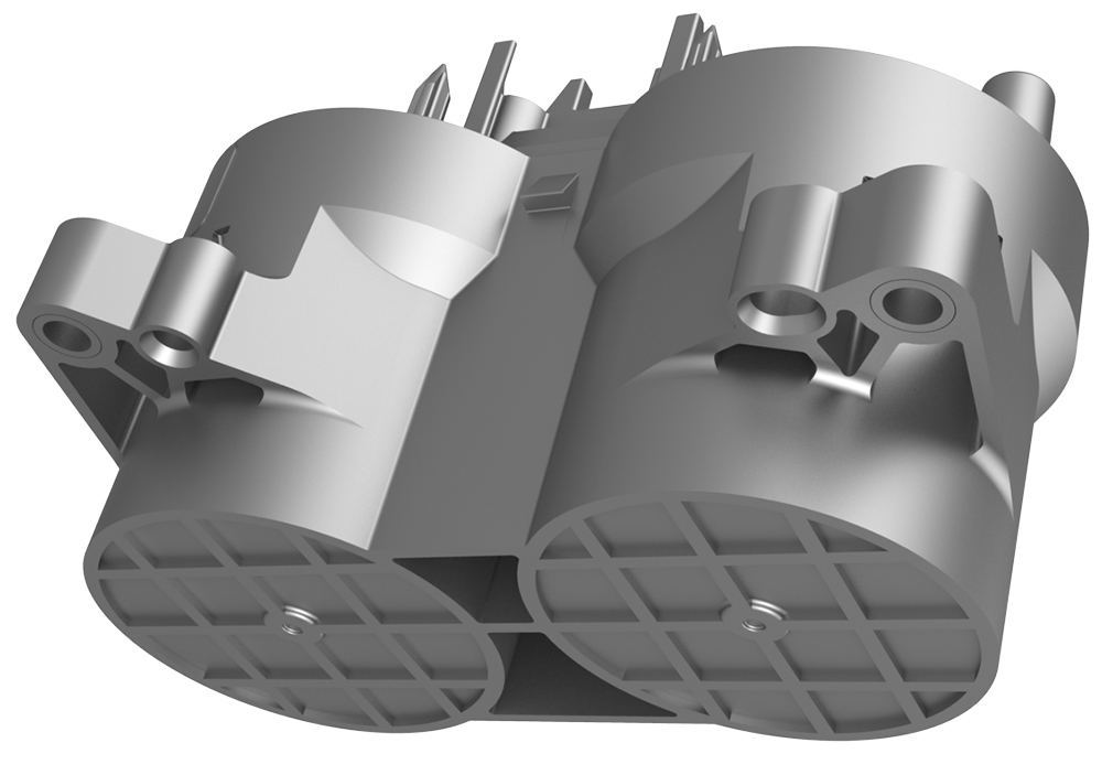
| 2 | Install the HV battery fast charge contactor to the insulator. Note: Align the 2 guides as the fast charge contactor is installed on the insulator.
| ||
| 3 | Install the bolts that attach the fast charge contactor to the insulator, and then mark the bolts with a paint pen after they are torqued. Torque 5.5 Nm | |
| 4 | Install the positive and negative inlet and DC link busbars to the fast charge contactor, install the new bolts (x4) that attach the busbars to the contactor, and then mark the bolts with a paint pen after they are torqued. Torque 9 Nm | |
Generic Measurement - Actual busbars and fasteners might appear different
| 5 | Use the Hioki resistance meter to measure the resistance between the positive (LH) HV joint bolt head of the fast charge contactor and the respective positive (LH) inlet busbar, and then the resistance between the positive (LH) HV joint bolt head of the fast charge contactor and the respective positive (LH) DC link busbar. Note: The maximum acceptable resistance is 0.030 mΩ (30 μΩ) per joint. If the resistance is above this value, escalate a Toolbox session, as appropriate.
| |
Generic Measurement - Actual busbars and fasteners might appear different
| 6 | Use the Hioki resistance meter to measure the resistance between the negative (RH) HV joint bolt head of the fast charge contactor and the respective negative (RH) inlet busbar, and then the resistance between the negative (RH) HV joint bolt head of the fast charge contactor and the respective negative (RH) DC link busbar. Note: The maximum acceptable resistance is 0.040 mΩ (40 μΩ) per joint. If the resistance is above this value, escalate a Toolbox session, as appropriate.
| |
| 7 | Install a new HV battery AC inlet harness to the fast charge contactor. See Harness - AC Inlet - HV Battery (Remove and Replace). Note: The AC inlet harness is a one time use.
| |
| 8 | Install the bolts and nut that attach the fast charge assembly to the penthouse, and then mark the bolts and nut with a paint pen after they are torqued. Torque 5.5 Nm Torque 8 Nm | |
| 9 | Install the clips that attach the HV battery penthouse harness to HV battery fast charge contactor cover. | |
| 10 | Install the DC input assembly to the penthouse, install the bolts (x4) that attach the DC input assembly to the penthouse, and then mark the bolts with a paint pen after they are torqued.. Torque 6 Nm | |
| 11 | Connect the electrical harness to the DC input assembly connector. | |
| 12 | Install new bolts (x4) to attach the negative and positive busbars to the DC links and DC input, and then mark the bolts with a paint pen after they are torqued. Torque 9 Nm | |
Generic Measurement - Actual busbars and fasteners might appear different
| 13 | Use the Hioki resistance meter to measure the resistance at the HV joint between the positive DC input busbar and the positive (LH) fast charge contactor busbar. Note: The maximum acceptable resistance is 0.060 mΩ (60 μΩ). If the resistance is above this value, escalate a Toolbox session, as appropriate.
| |
Generic Measurement - Actual busbars and fasteners might appear different
| 14 | Use the Hioki resistance meter to measure the resistance at the HV joint between the positive (LH) DC link busbar and the positive (LH) fast charge contactor busbar. Note: The maximum acceptable resistance is 0.040 mΩ (40 μΩ). If the resistance is above this value, escalate a Toolbox session, as appropriate.
| |
Generic Measurement - Actual busbars and fasteners might appear different
| 15 | Use the Hioki resistance meter to measure the resistance at the HV joint between the negative DC input busbar and the negative (RH) fast charge contactor busbar. Note: The maximum acceptable resistance is 0.060 mΩ (60 μΩ). If the resistance is above this value, escalate a Toolbox session, as appropriate.
| |
Generic Measurement - Actual busbars and fasteners might appear different
| 16 | Use the Hioki resistance meter to measure the resistance at the HV joint between the negative (RH) DC link busbar and the negative (RH) fast charge contactor busbar. Note: The maximum acceptable resistance is 0.060 mΩ (60 μΩ). If the resistance is above this value, escalate a Toolbox session, as appropriate.
| |
| 17 | Install the insulator for the DC input assembly. | |
| 18 | Fasten the clips that attach the HV battery AC inlet harness cover to the power conversion system. | |
| 19 | Connect the HV battery AC inlet harness to the power conversion system connector. | |
| 20 | Connect the electrical harness to the HV battery fast charge contactor connector. | |
| 21 | Install the HV battery probing guide into the penthouse, and then fasten the clips that attach the guide to the HV battery. | |
| 22 | Install the clip that attaches the HV battery penthouse harness to the HV battery fast charge contactor. | |
| 23 | Install the power conversion system coolant output tube. See Tube - Output - Coolant - Power Conversion System (Remove and Replace). Caution: Make sure that the coolant output tube is securely connected by firmly pressing down on the fittings, verify that both clips have fully engaged the barb on the power conversion system and battery flange, and then pull up on the fittings to check retention.
| ||
| 24 | Perform a penthouse coolant leak test. See Penthouse Coolant Leak Test. | ||
| 25 | Connect the 12V auxiliary battery negative terminal only. Torque 6 Nm Caution: Do not follow the procedure to connect 12V power at this time.
| ||
| 26 | Connect a 12V charger to the 12V auxiliary battery terminals. | ||
| 27 | Refill the coolant. See Penthouse Coolant (Drain and Refill). | ||
| 28 | On the touchscreen, touch . | ||
| 29 | Disconnect the 12V charger from the 12V auxiliary battery terminals. | ||
| 30 | Disconnect the 12V auxiliary battery negative terminal. | ||
| 31 | Install the HV battery negative contactor. See Contactor - Negative - HV Battery (Remove and Replace). |