Powertrain Coolant (Drain and Refill)
Correction code 4020200040202000
- 1053600-00-C Drive Unit Pressure Test Fixture
- 1132185-00-B Kit, Coolant Leak Test Adapters, Model 3
- 1133843-00-AKit, Coolant Drain & Fill Adapters, M3
- 1135762-00-AKit, Svc Plug, Cooling Hose, Model 3
- GSN-TL-000564Kit, Battery Coolant Drain and Fill
SPECIAL TOOLS
Drive Unit Pressure Test Fixture (1053600-00-C) |
Kit, Coolant Leak Test Adapters, Model 3 (1132185-00-B) |
Kit, Coolant Drain & Fill Adapters, M3 (1133843-00-A) |
Kit, Svc Plug, Cooling Hose, Model 3 (1135762-00-A) |
Kit, Battery Coolant Drain and Fill (GSN-TL-000564) |
Drain
-
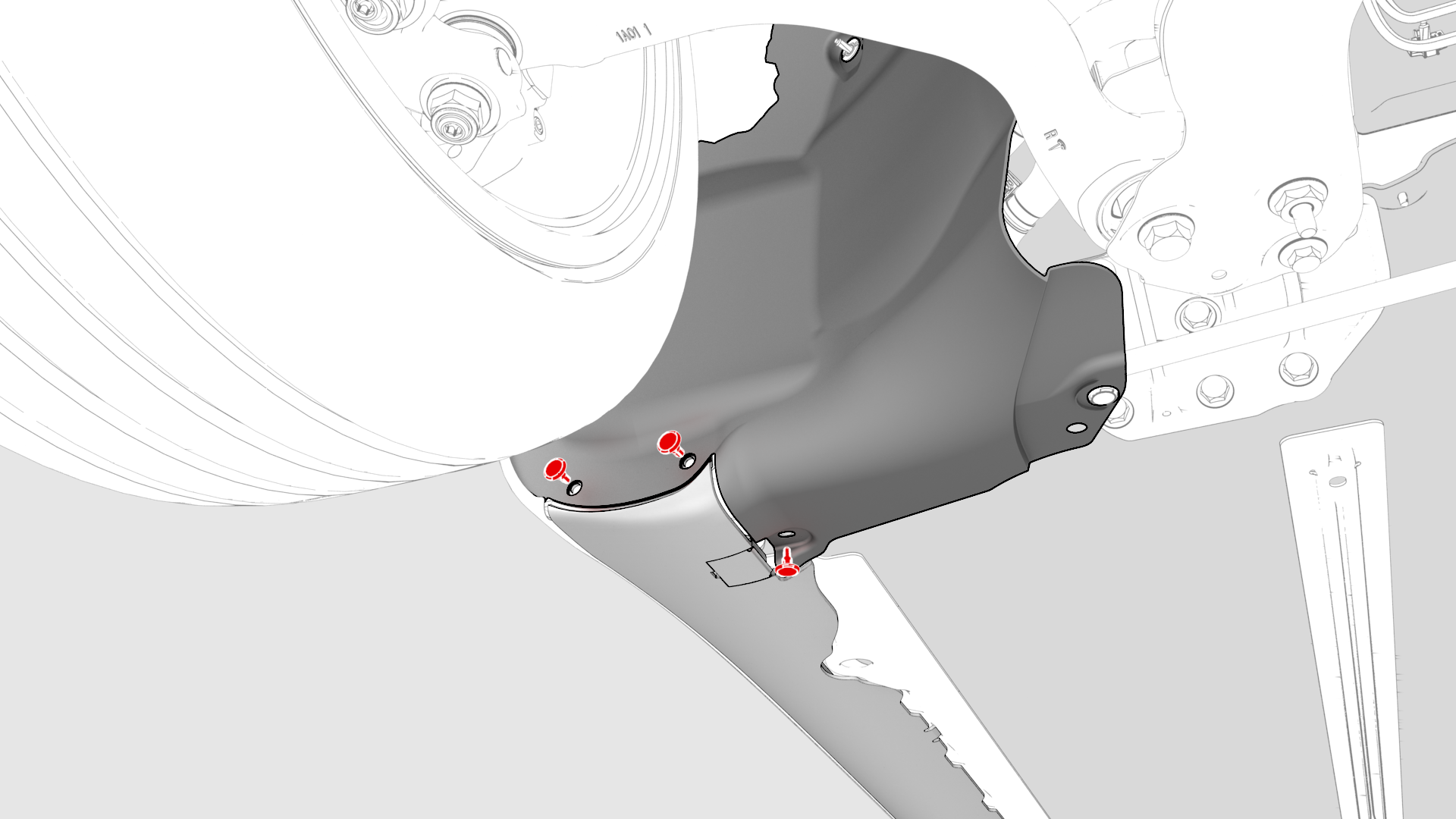
Remove the lower clips (x3) that attach the lower rear edge of the RH wheel arch liner to the body, to allow access to the coolant hose.
-
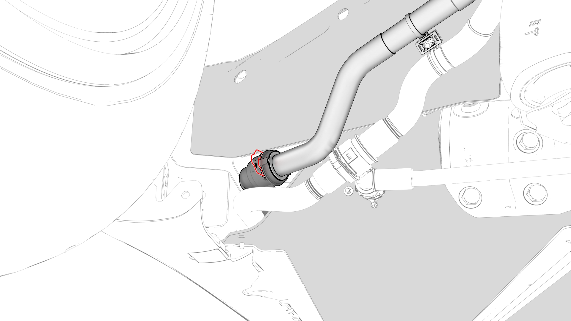
Disconnect the rear powertrain supply hose at the RH side of the vehicle, plug the male fitting, and allow the female fitting to drain.
-
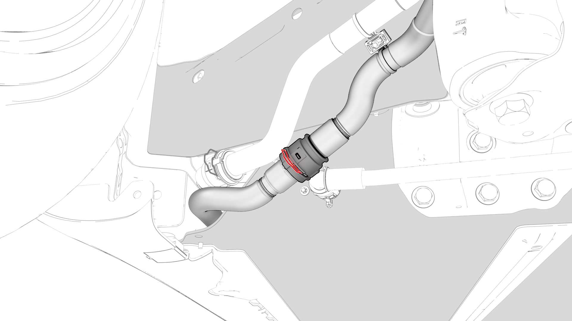
Disconnect the powertrain return hose at the RH side of the vehicle, plug the female fitting, and allow the male fitting to drain.
| 1 | Disconnect 12V power. See 12V Power (Disconnect and Connect). | ||
| 2 | Remove the front HV battery skid plate. See Skid Plate - HV Battery - Front (Remove and Replace). | ||
| 3 | Remove the lower clips (x3) that attach the lower rear edge of the RH wheel arch liner to the body, to allow access to the coolant hose. | |
| 4 | Position a coolant drain under the front RH corner of the HV battery. | ||
| 5 | Disconnect the rear powertrain supply hose at the RH side of the vehicle, plug the male fitting, and allow the female fitting to drain. | |
| 6 | Connect the coolant pressure test adapter to the female fitting. | ||
| 7 | Connect the drive unit pressure test fixture to the coolant pressure test adapter. | ||
| 8 | Close both valves P1 (inlet) and P2 (outlet) on the test fixture, and connect a compressed air supply line. | ||
| 9 | Fully close the regulator, and then open P1 (inlet valve). | ||
| 10 | Set the pressure regulator of the test fixture to 26 psi. | ||
| 11 | Disconnect the powertrain return hose at the RH side of the vehicle, plug the female fitting, and allow the male fitting to drain. | |
| 12 | Connect the coolant drain adapter to the male connector, and direct the tube to the coolant drain. | ||
| 13 | Slowly open P2 (outlet valve) to speed the drain. | ||
| 14 | Wait at least 5 minutes for the coolant to fully drain. | ||
| 15 | Close P2 (outlet valve) when no more coolant is expelled. | ||
| 16 | Disconnect the air supply from the test fixture. | ||
| 17 | Remove the coolant pressure test adapter and coolant drain adapter from the hoses | ||
| 18 | Perform the service procedures that required the powertrain coolant to be drained. | ||
| 19 | After the components have been replaced, refill the coolant. See Refill. |
Refill
-
Connect the powertrain supply hose to the male fitting.
 Caution:Perform a push-pull test to verify that the hose is fully seated.
 -
Connect the powertrain return hose to the female fitting.
Caution:Perform a push-pull test to verify that the hose is fully seated.
-
Install the lower clips (x3) that attach the lower rear edge of the RH wheel arch liner to the body.
| 1 | Remove the plugs from the hoses. | ||
| 2 | Connect the powertrain supply hose to the male fitting. Caution: Perform a push-pull test to verify that the hose is fully seated.
| |
| 3 | Connect the powertrain return hose to the female fitting. Caution: Perform a push-pull test to verify that the hose is fully seated.
| |
| 4 | Install the lower clips (x3) that attach the lower rear edge of the RH wheel arch liner to the body. | |
| 5 | Install the front HV battery skid plate. See Skid Plate - HV Battery - Front (Remove and Replace). | ||
| 6 | Remove the coolant drain from under the vehicle. | ||
| 7 | Install the mid aero shield panel. See Panel - Aero Shield - Mid (Remove and Replace). | ||
| 8 | Connect 12V power. See 12V Power (Disconnect and Connect). | ||
| 9 | Perform a vacuum refill of the cooling system. See Cooling System (Vacuum Refill). |