Connectivity Board - Car Computer (Remove and Replace)
Correction code 2115280221152802
from-rc
Note:
This procedure was formulated using a release candidate or production model. Follow safety requirements and use extreme caution when working on or near high-voltage systems and components.
Provide corrections and feedback to servicemanualfeedback@tesla.com.
Remove
-
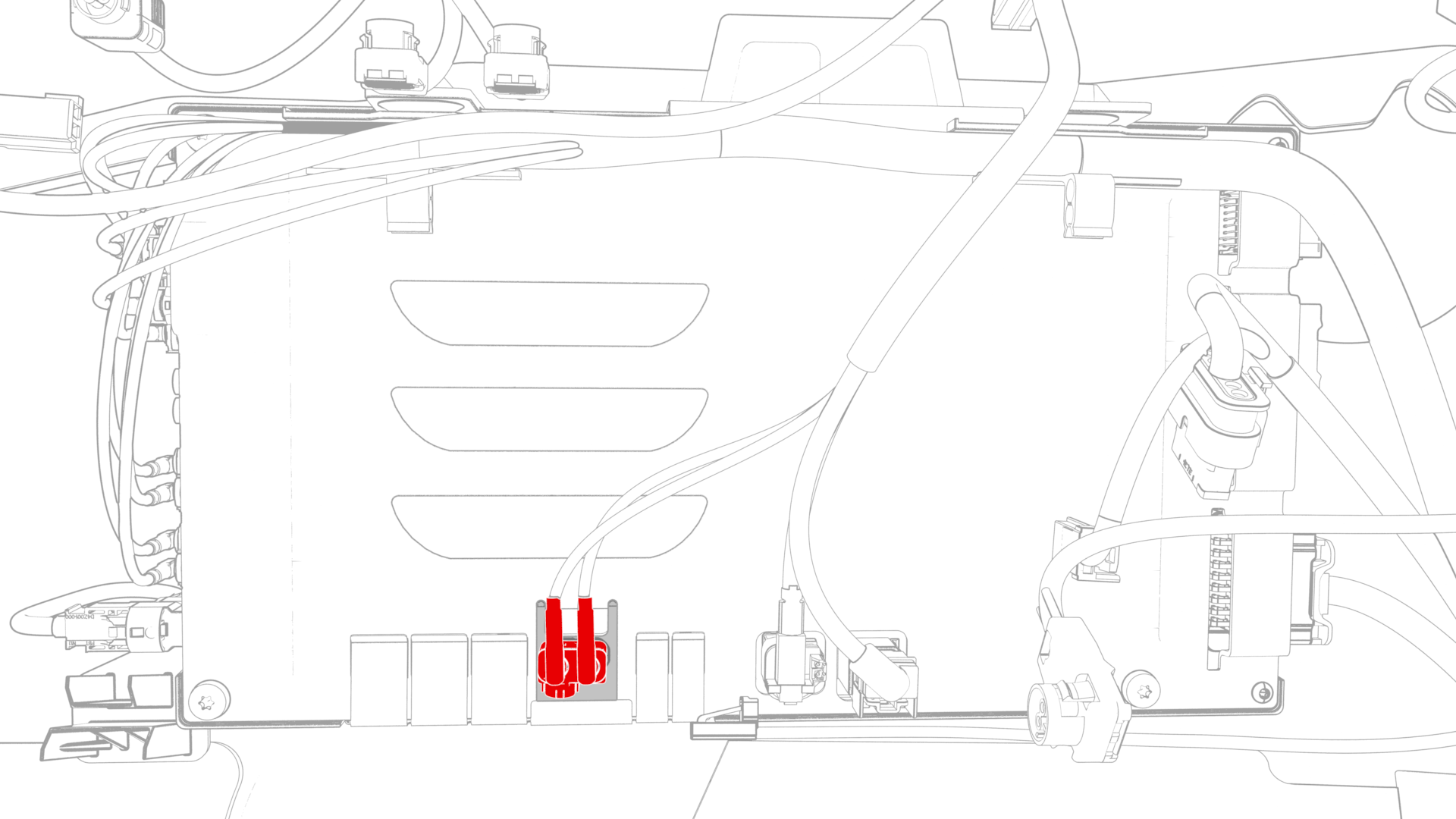
Disconnect the electrical connector from the connectivity board.
-
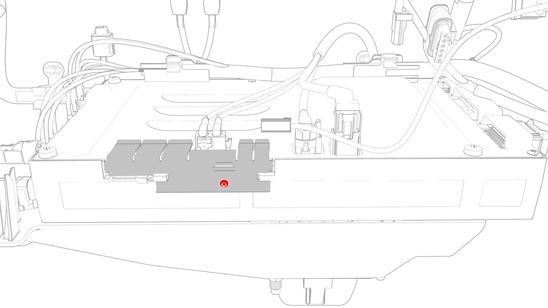
Remove the bolt that attaches the connectivity board to the car computer.
-
Carefully slide the connectivity board downwards, and then remove the board from the car computer.
 Caution:Do not pull on the double Fakra electrical connector. Push on the outer tabs to release the board from the car computer.
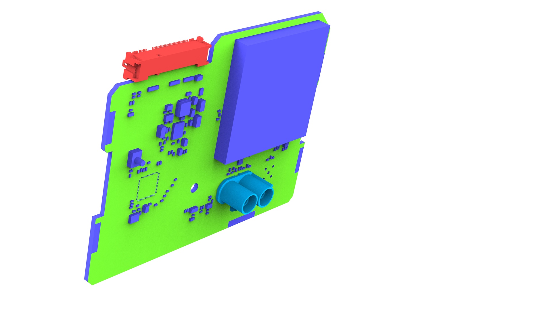
| 1 | Remove the front passenger knee airbag. See Airbag - Knee - Front Passenger (Remove and Replace). | ||
| 2 | Disconnect the electrical connector from the connectivity board. | |
| 3 | Remove the bolt that attaches the connectivity board to the car computer. | |
| 4 | Carefully slide the connectivity board downwards, and then remove the board from the car computer. Caution: Do not pull on the double Fakra electrical connector. Push on the outer tabs to release the board from the car computer.
|
Install
-
Install the bolt that atttches the connectivity board to the car computer.
 Torque 1 Nm
| 1 | Locate the connectivity board into the car computer aperture. Note: Use the top cover and car computer frame for initial guidance.
|
| 2 | Carefully press the front face of the connectivity board into the car computer. |
| 3 | Confirm that the connectivity board is fully inserted; slide the connectivity board about 80% inward, and then slightly press the double Fakra connector until the connectivity board is fully seated. Note: The LTE cassette must be sub-flush of the car computer frame before continuing to the next step.
|
| 4 | Install the bolt that atttches the connectivity board to the car computer. Torque 1 Nm |
| 5 | Connect the electrical connector to the connectivity board. |
| 6 | Install the front passenger knee airbag. See Airbag - Knee - Front Passenger (Remove and Replace). |
| 7 | Use Toolbox to update the vehicle firmware. |
| 8 | Perform a functional check of the LTE service. |