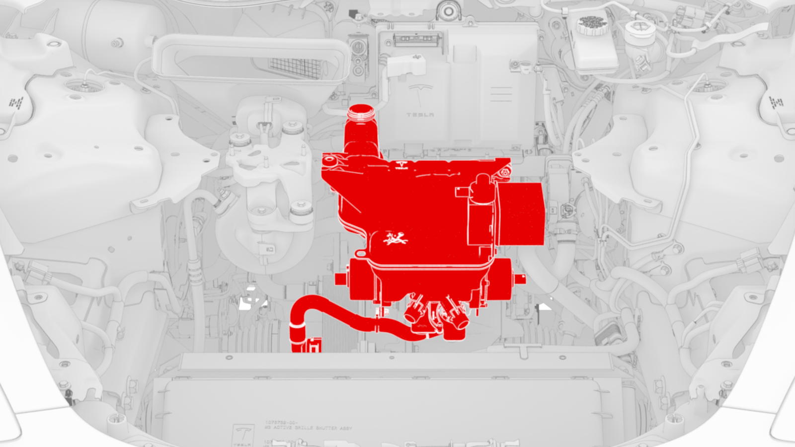
Superbottle (Dual Motor) (Remove and Replace)
Correction code 1830151218301512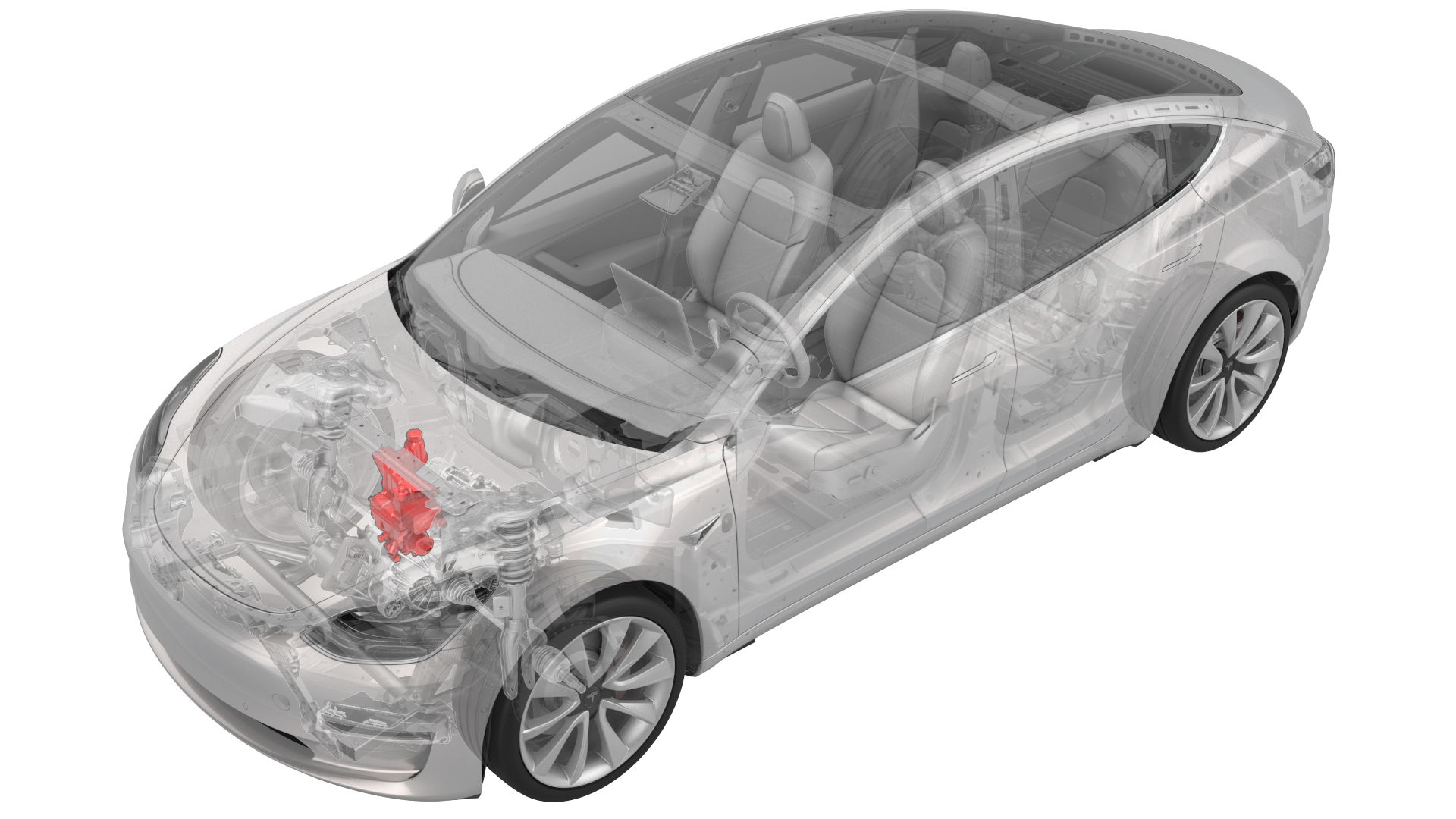
- 1135762-00-AKit, Svc Plug, Cooling Hose, Model 3
SPECIAL TOOLS
Kit, Svc Plug, Cooling Hose, Model 3 (1135762-00-A) |
Remove
-
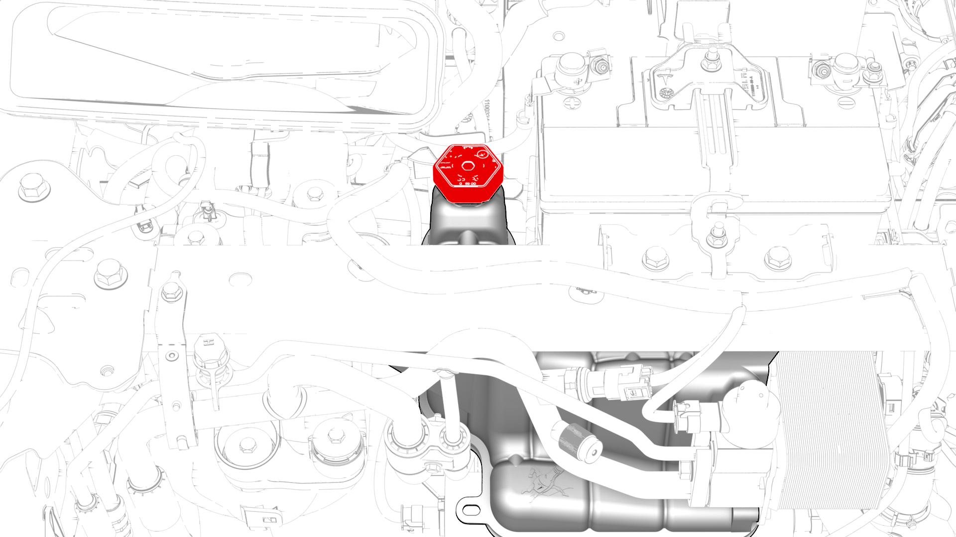
Remove the superbottle cap.
-
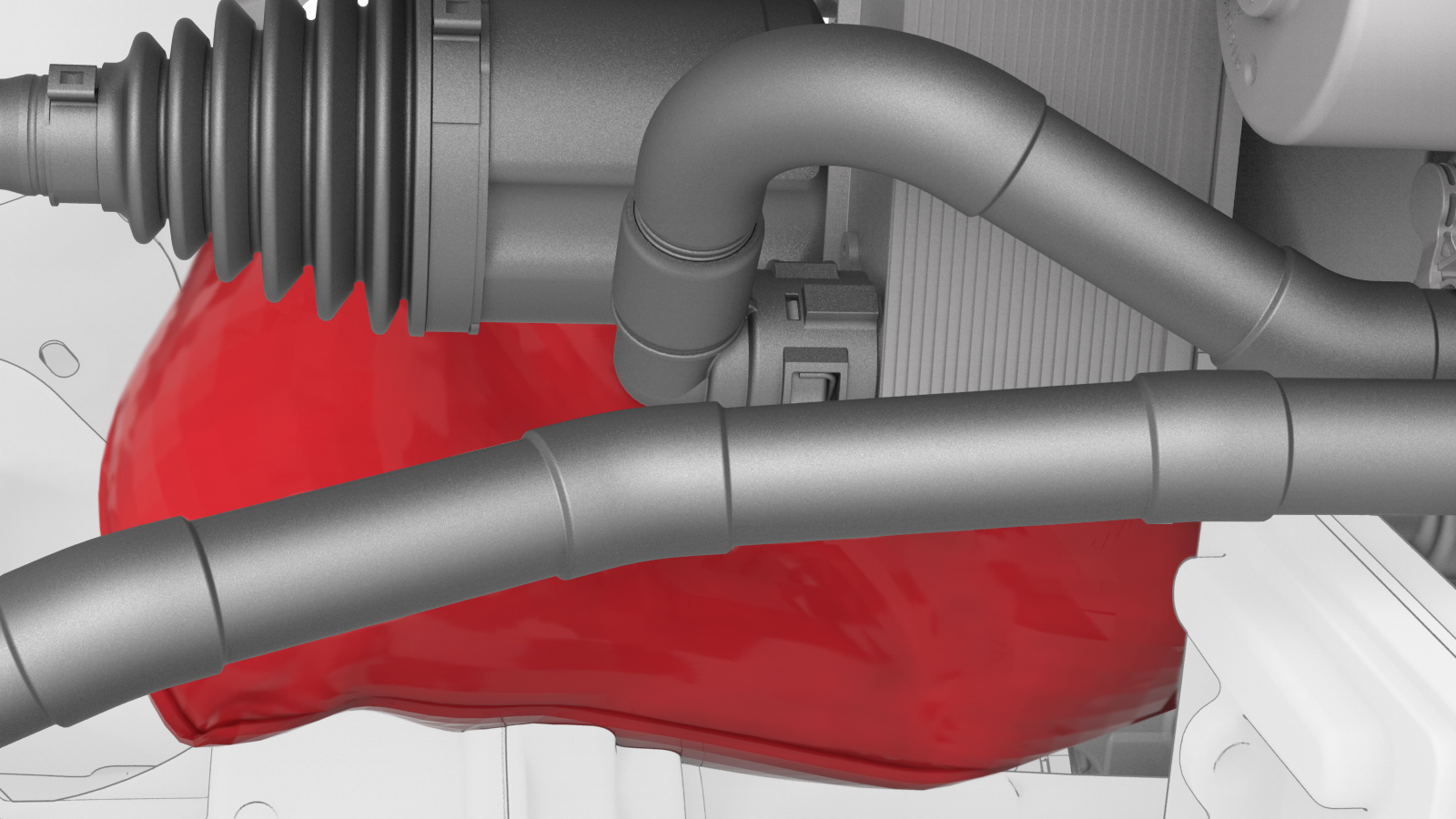
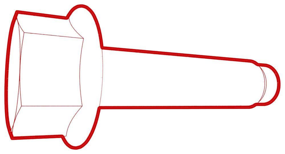
Install a foldable funnel underneath the heat exchanger, as shown.
Note: Make sure the foldable funnel covers the front drive unit 12V connector, steering rack, and is positioned to catch fluid from the heat exchanger coolant outlet.
-
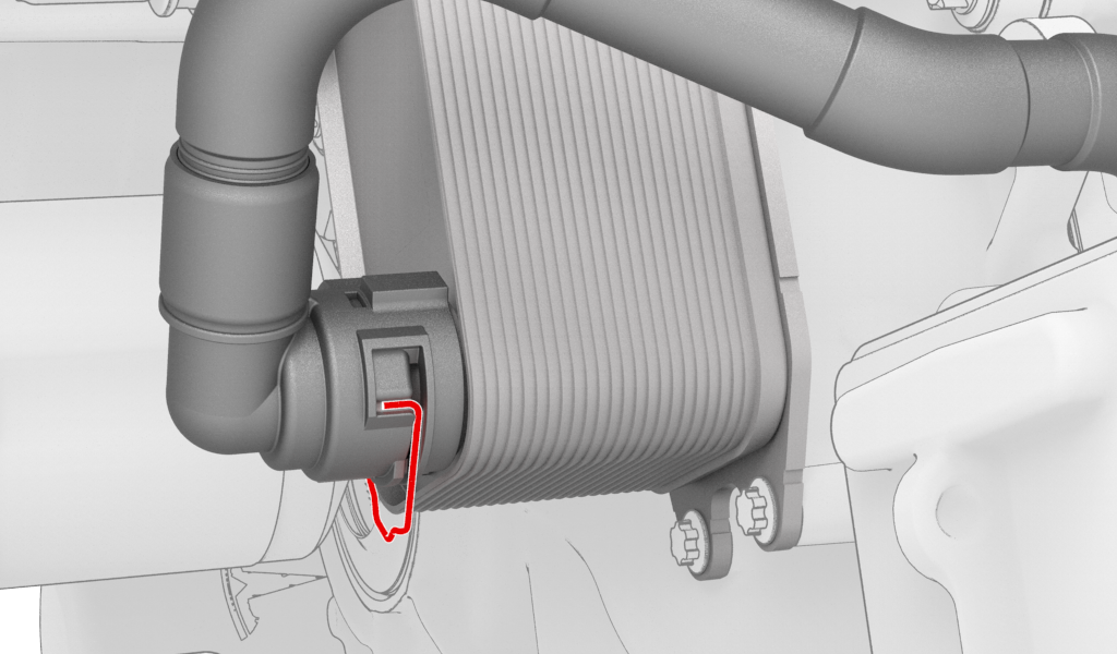
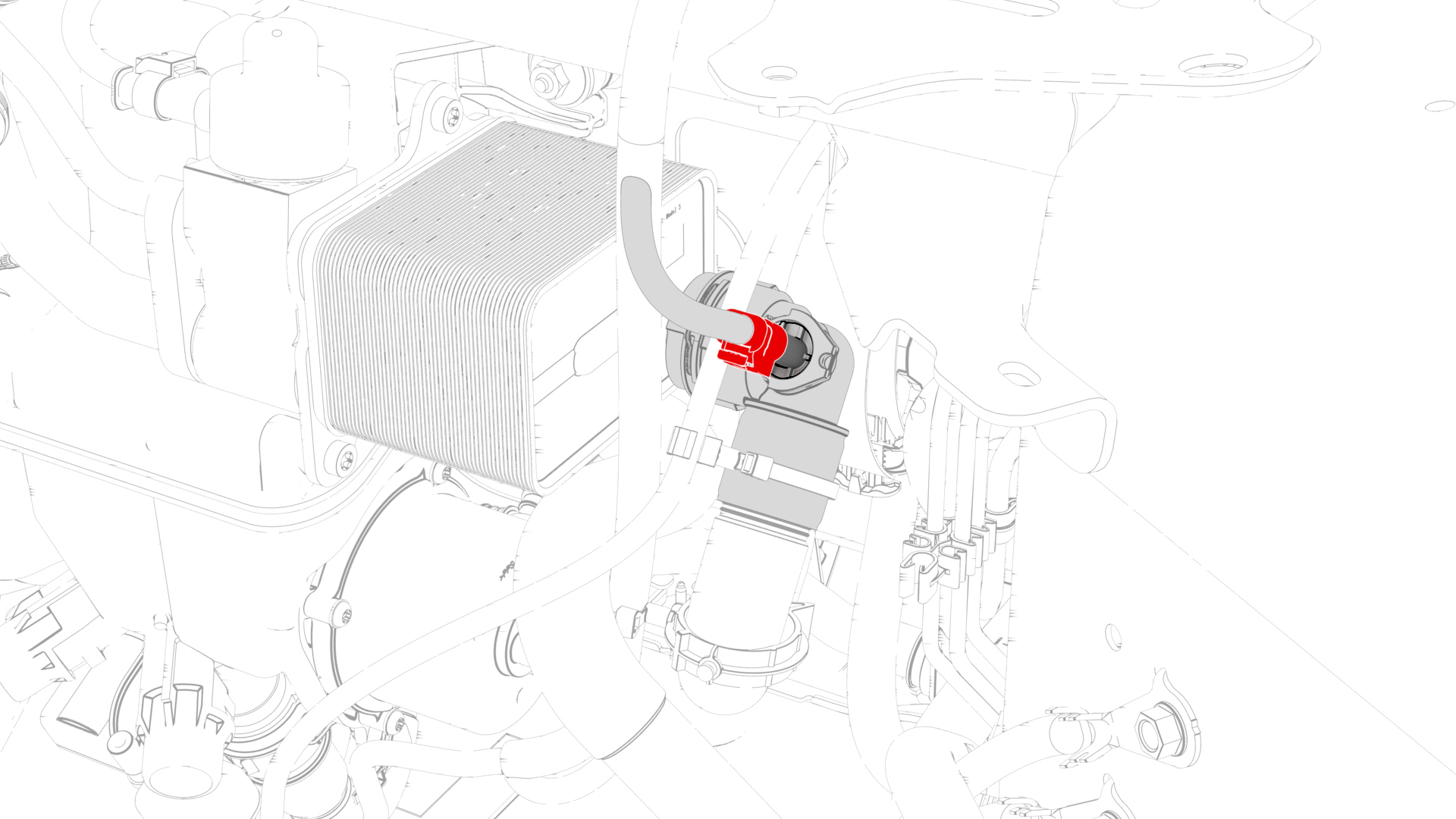
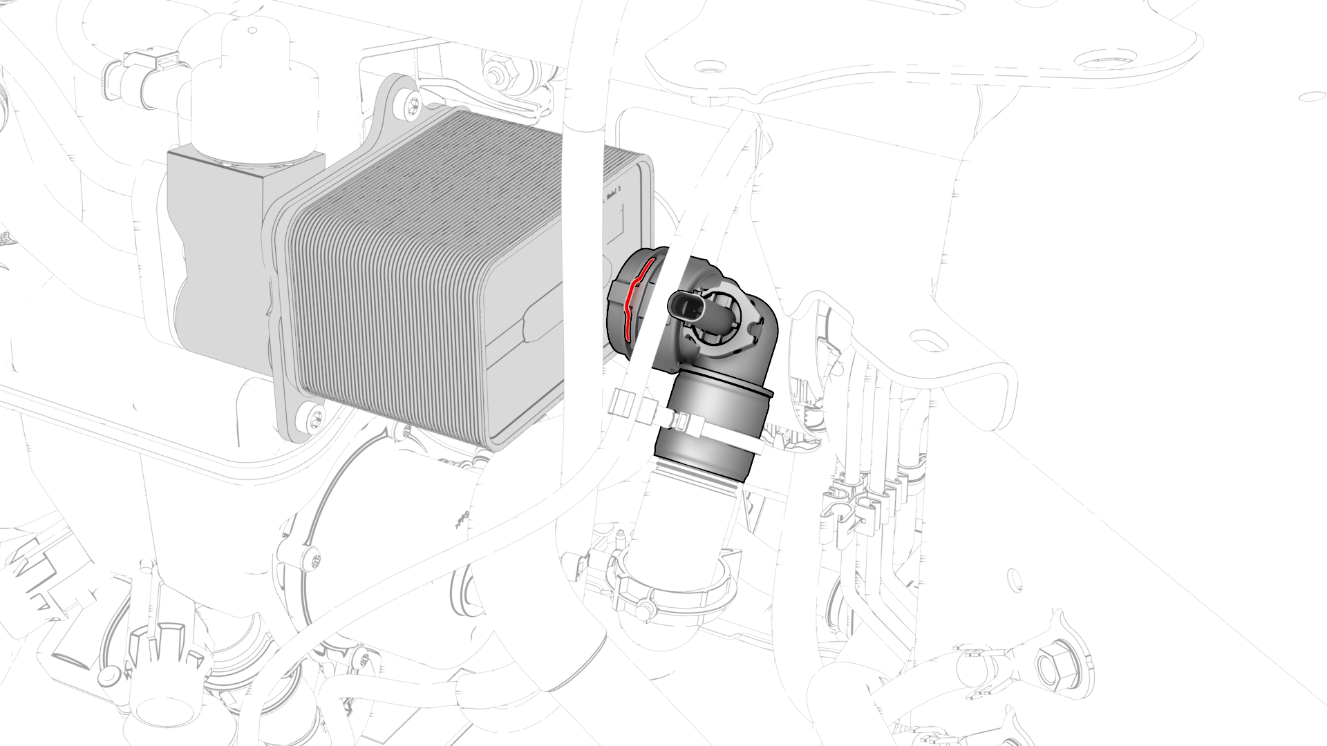
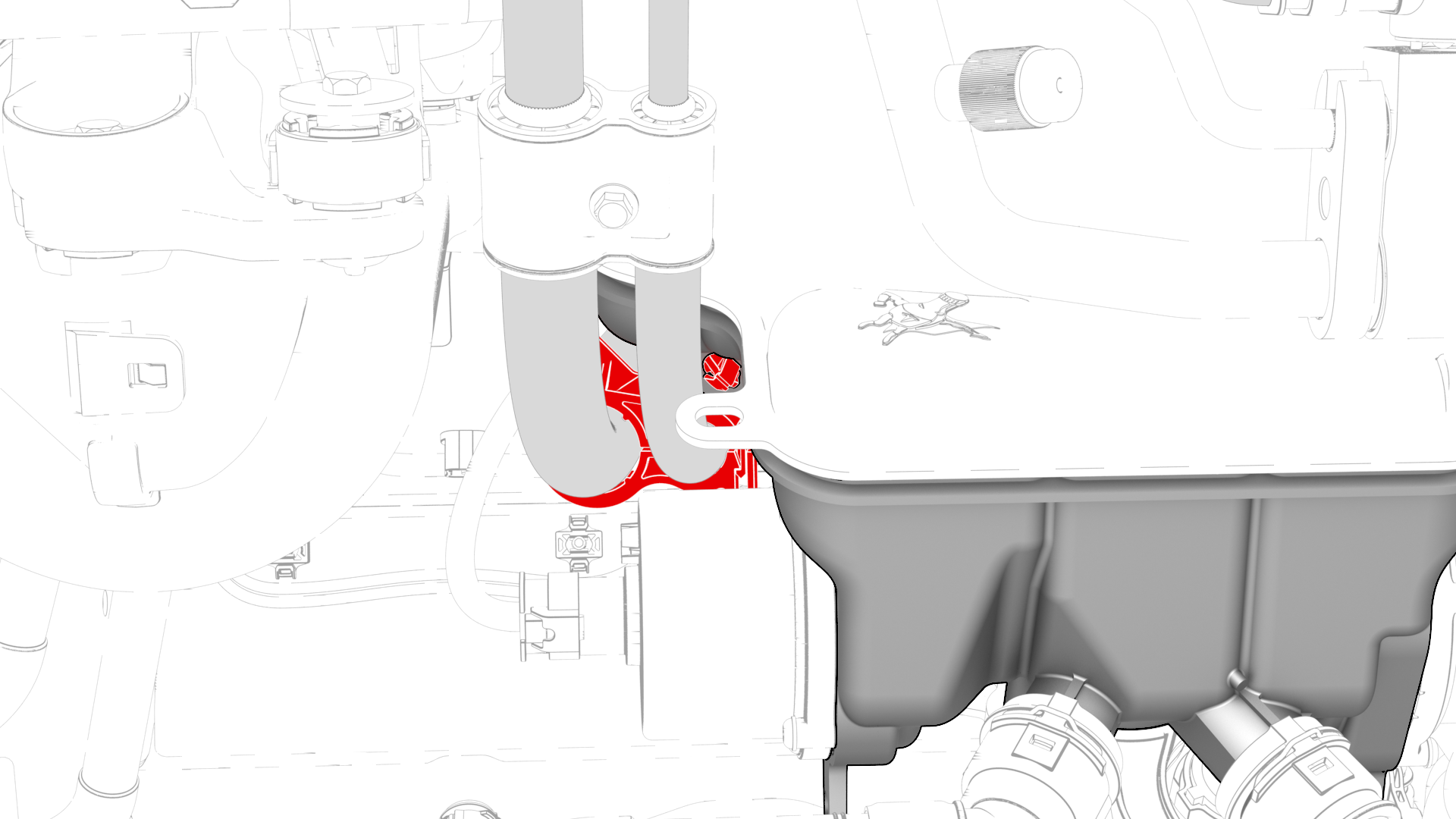
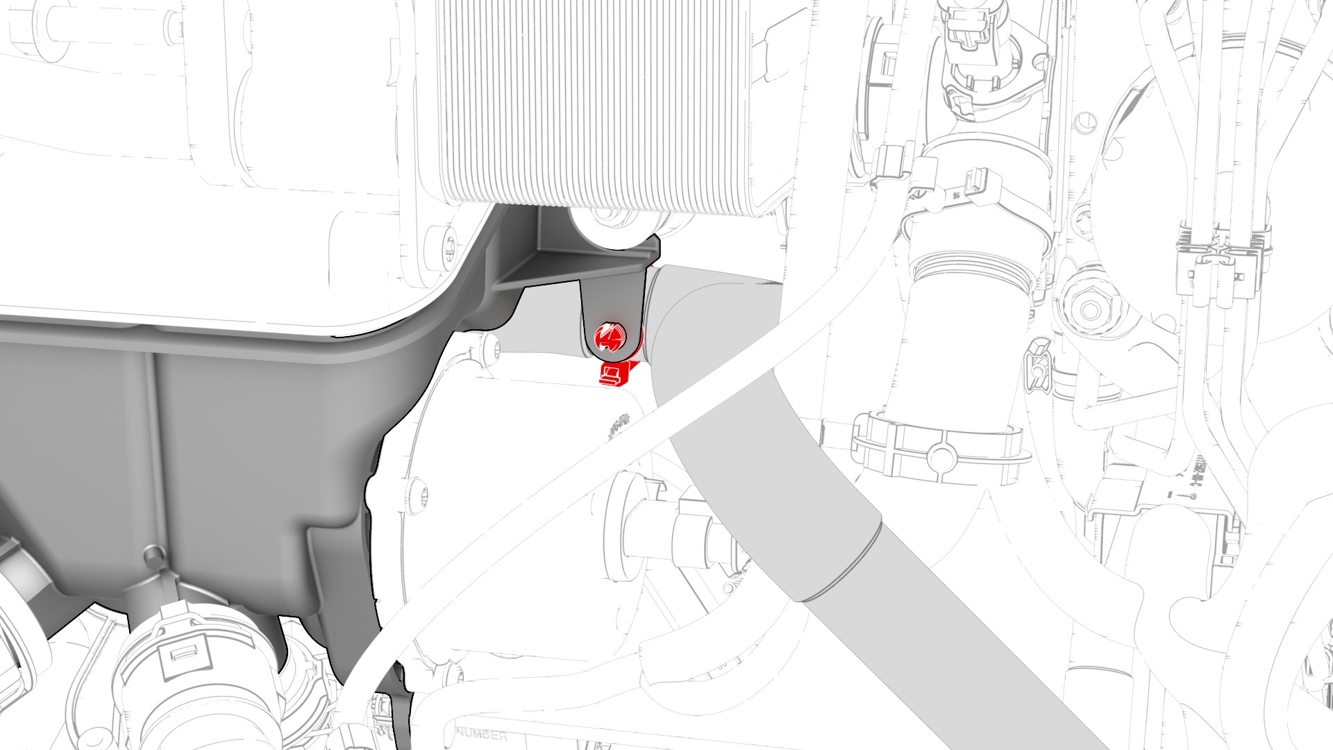
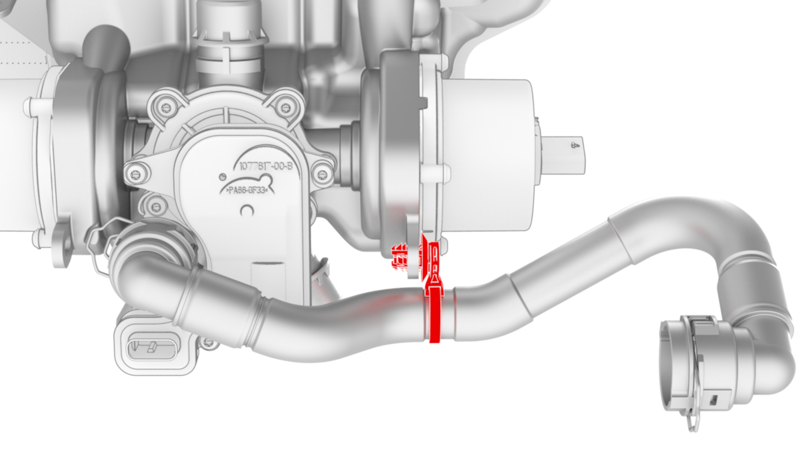
Release the clip that connects the front drive unit heat exchanger-superbottle hose to the heat exchanger coolant outlet, and then drain the coolant into the coolant drain container.
-
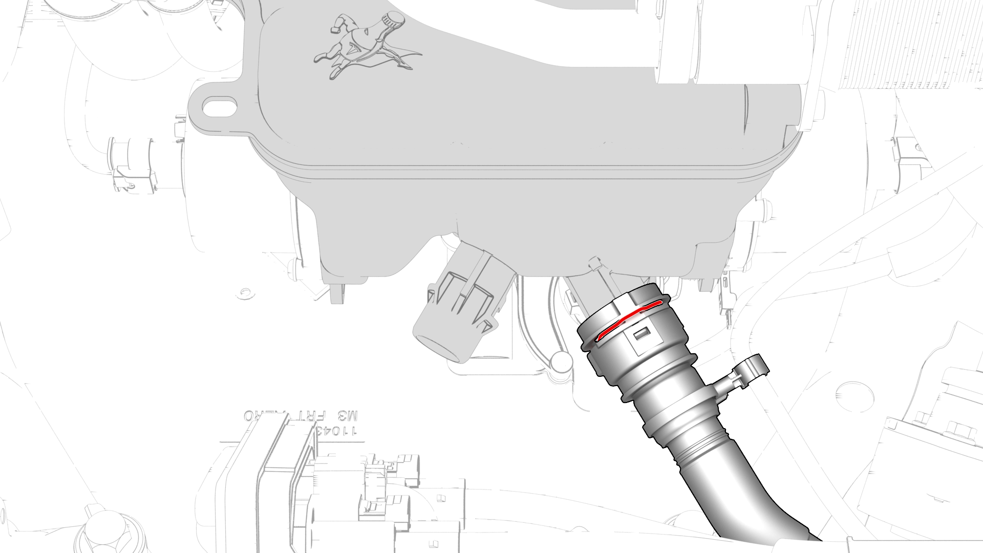
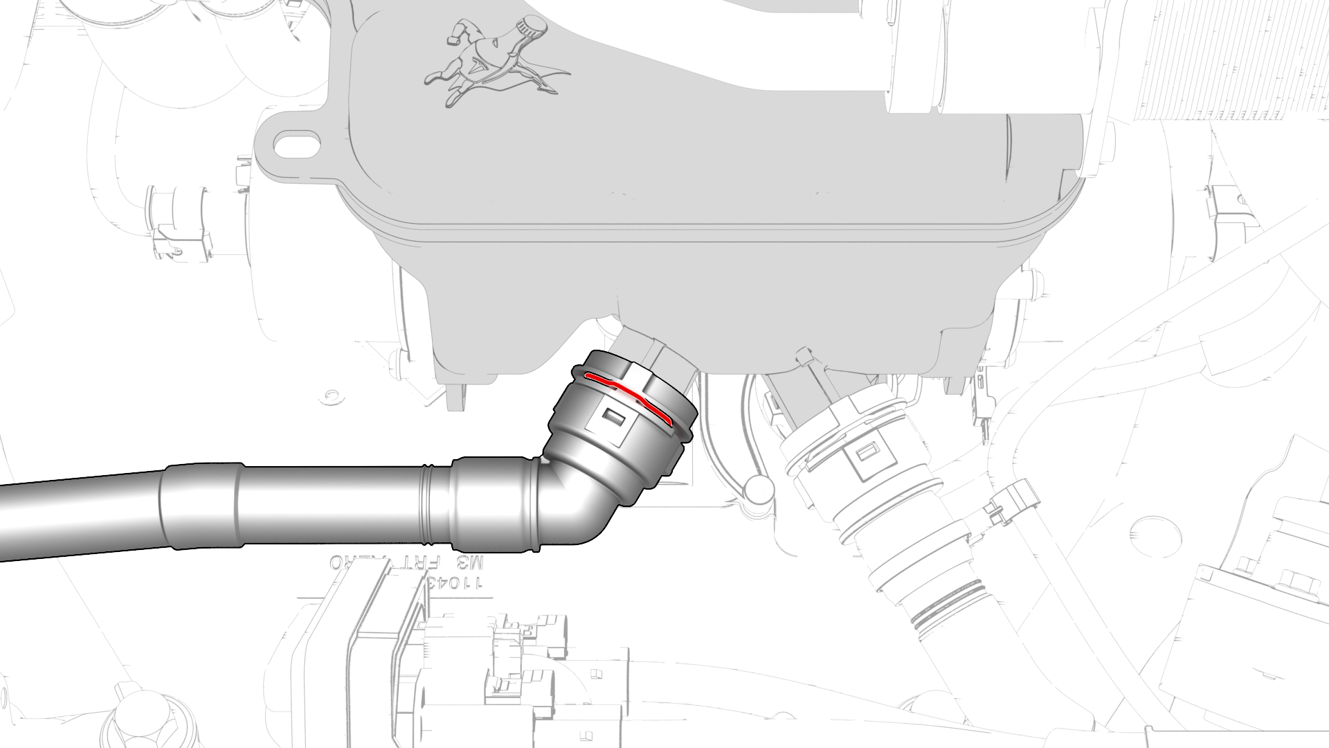
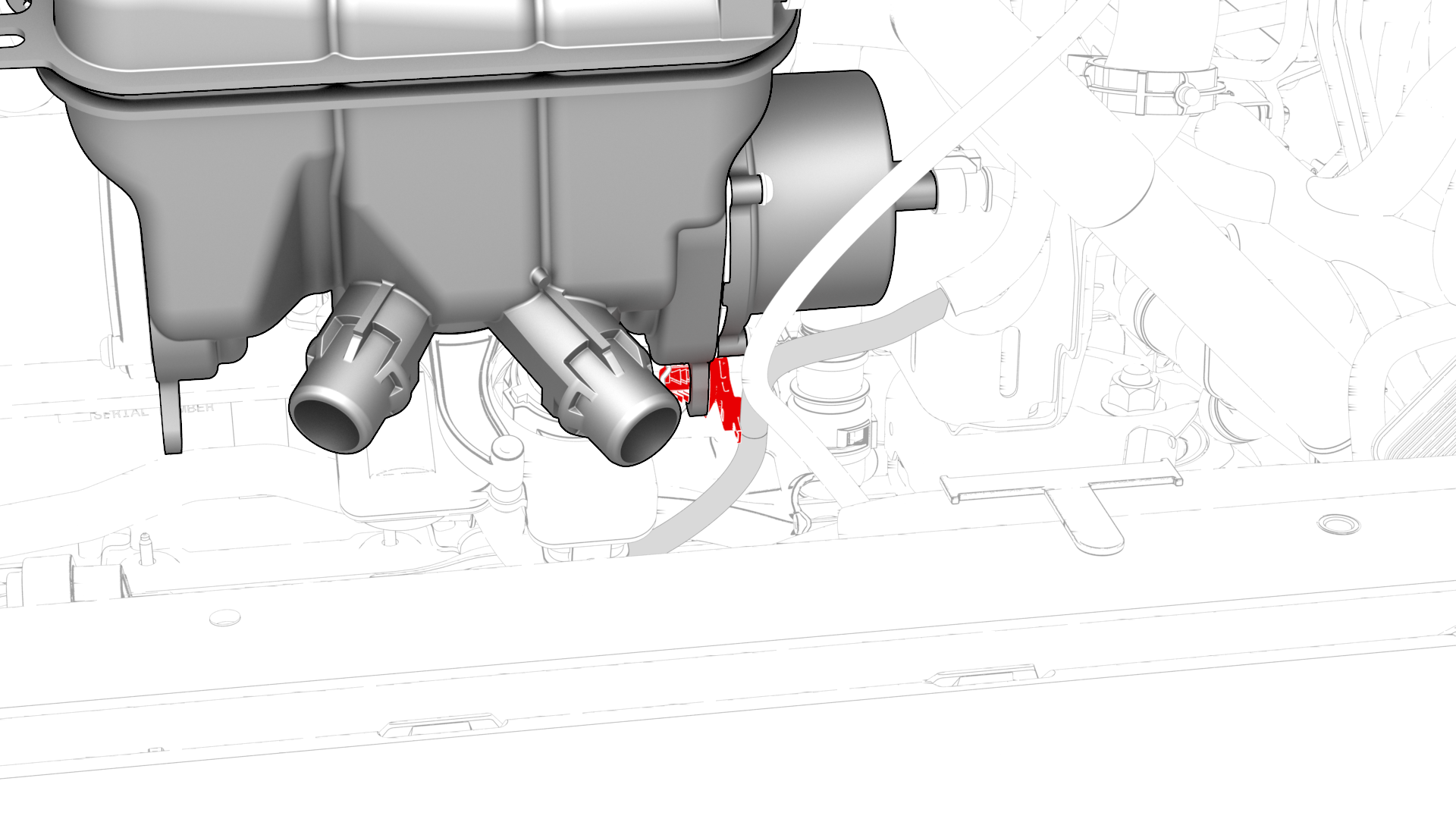
Release the clip and disconnect the radiator inlet hose from the front left of the superbottle.
-
Release the clip and disconnect the radiator outlet hose from the front right of the superbottle.
-
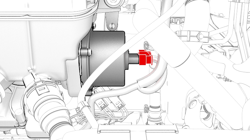
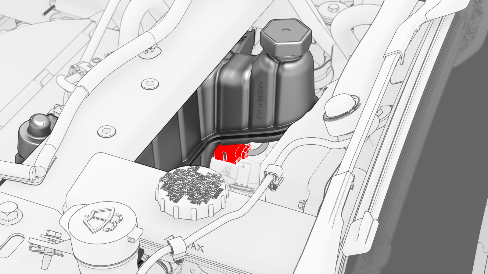
Disconnect the electrical harness from the chiller and EXV assembly hose coolant temperature sensor connector.
-
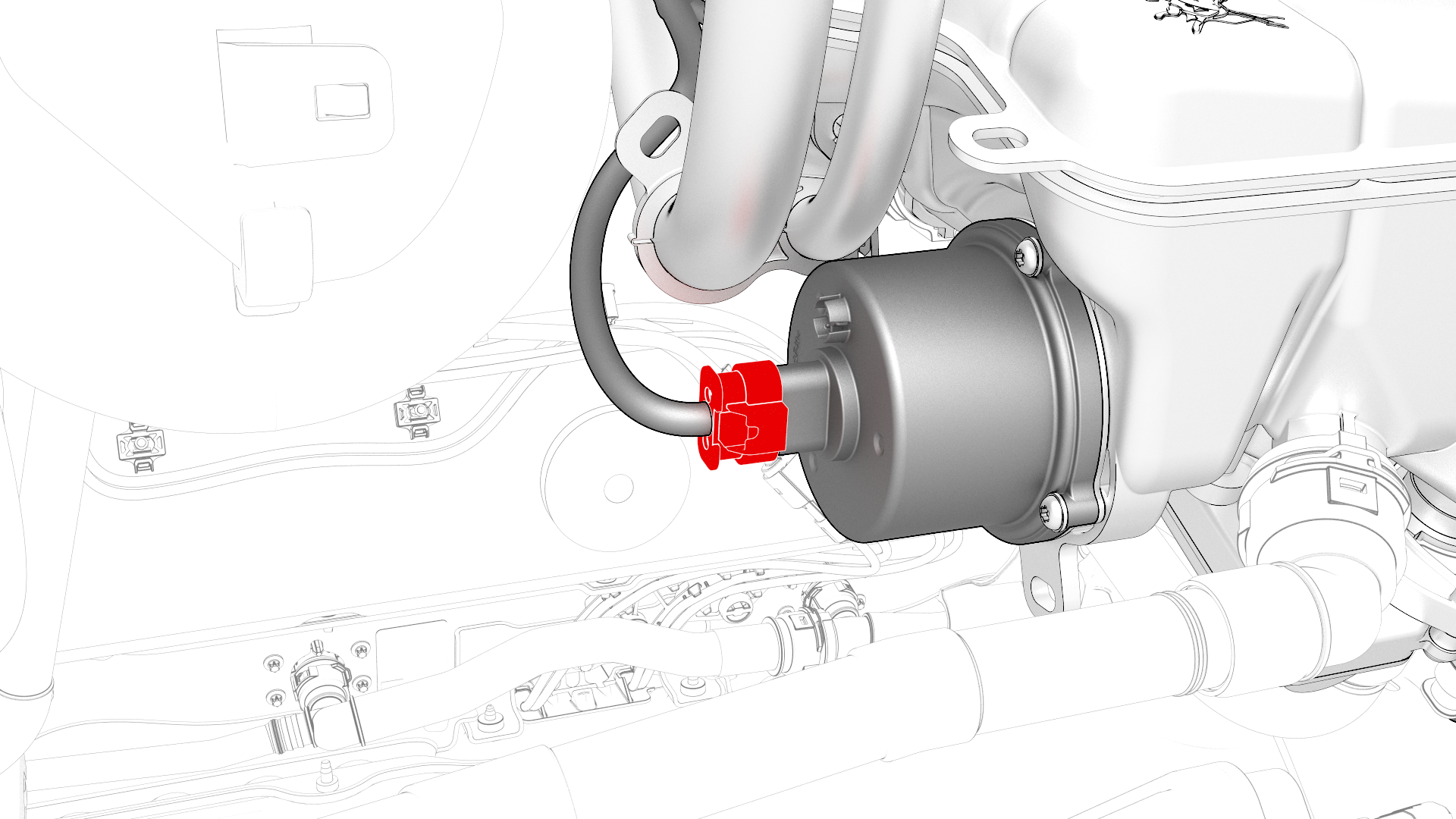
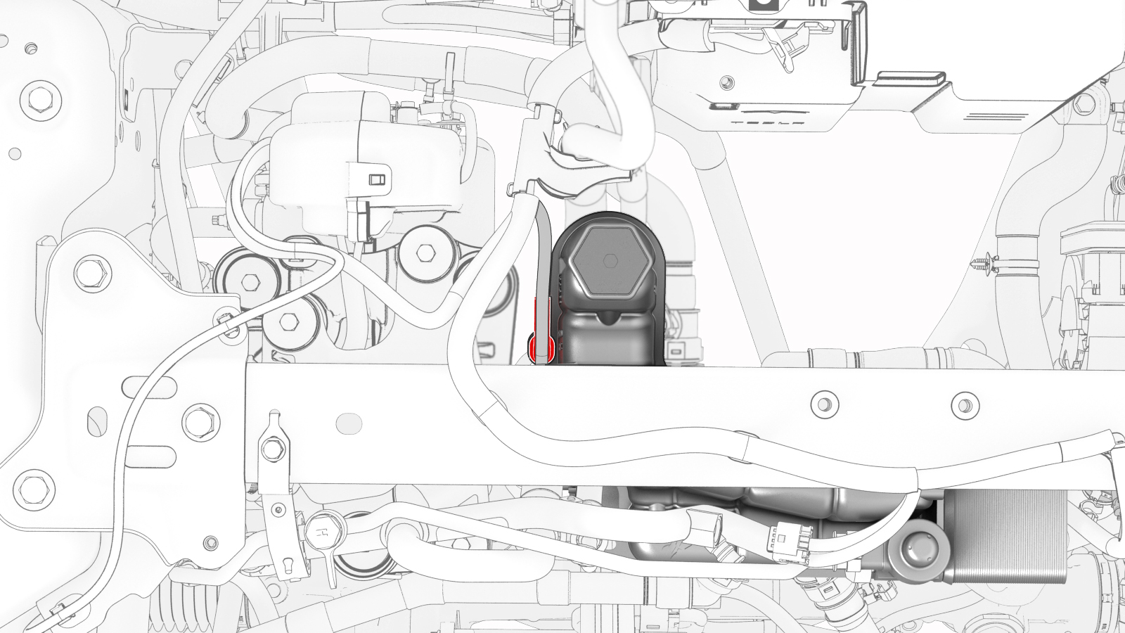
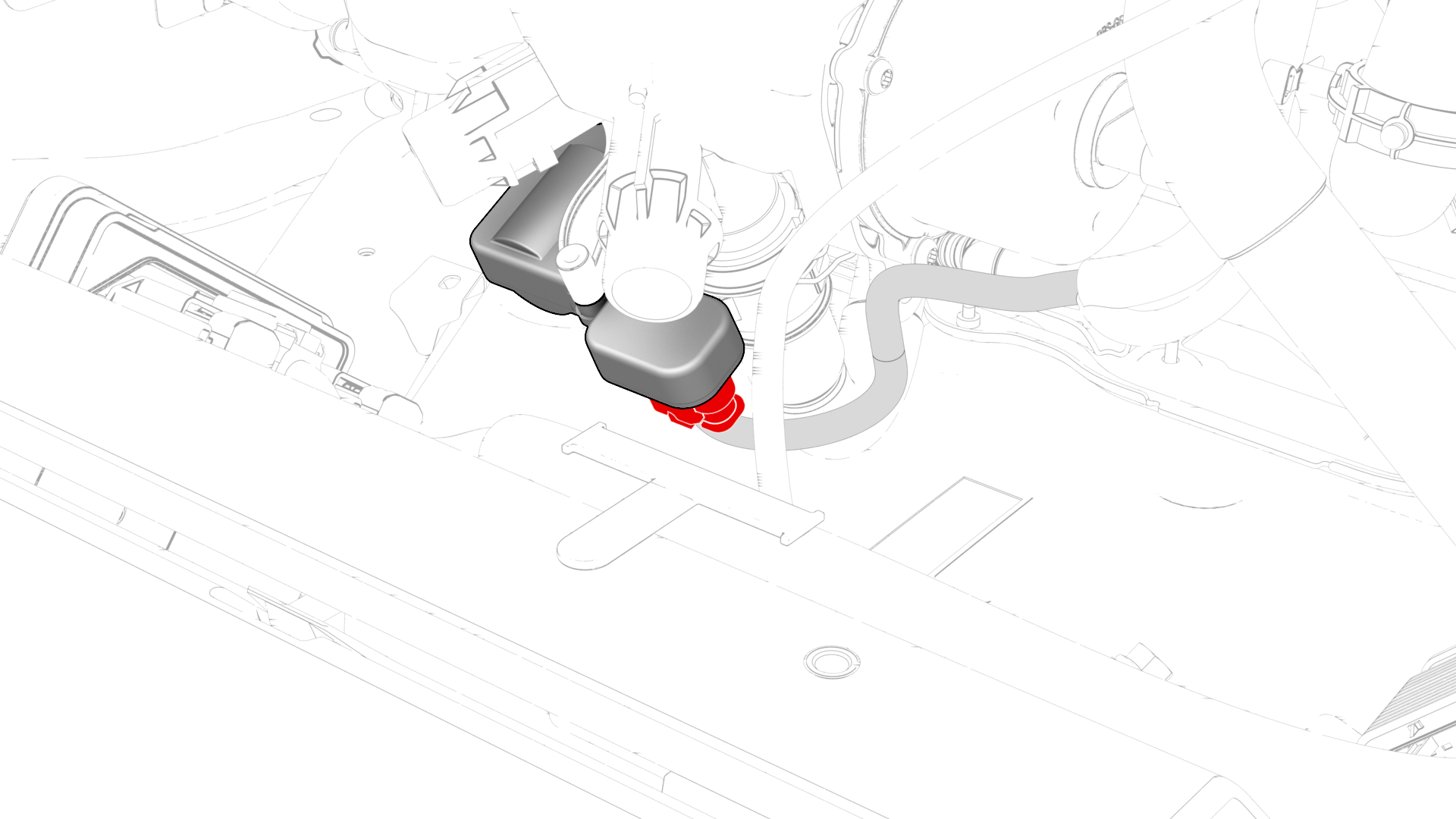
Release the clip and disconnect the coolant hose from the chiller and EXV assembly.
-
Disconnect the electrical harness from the HV battery coolant pump connector.
-
Disconnect the electrical harness from the powertrain coolant pump connector.
-
Disconnect the electrical harness from the powertrain pump to sill hose coolant temperature sensor connector.
 Tip: Tilt the superbottle toward the front of the vehicle for better access.
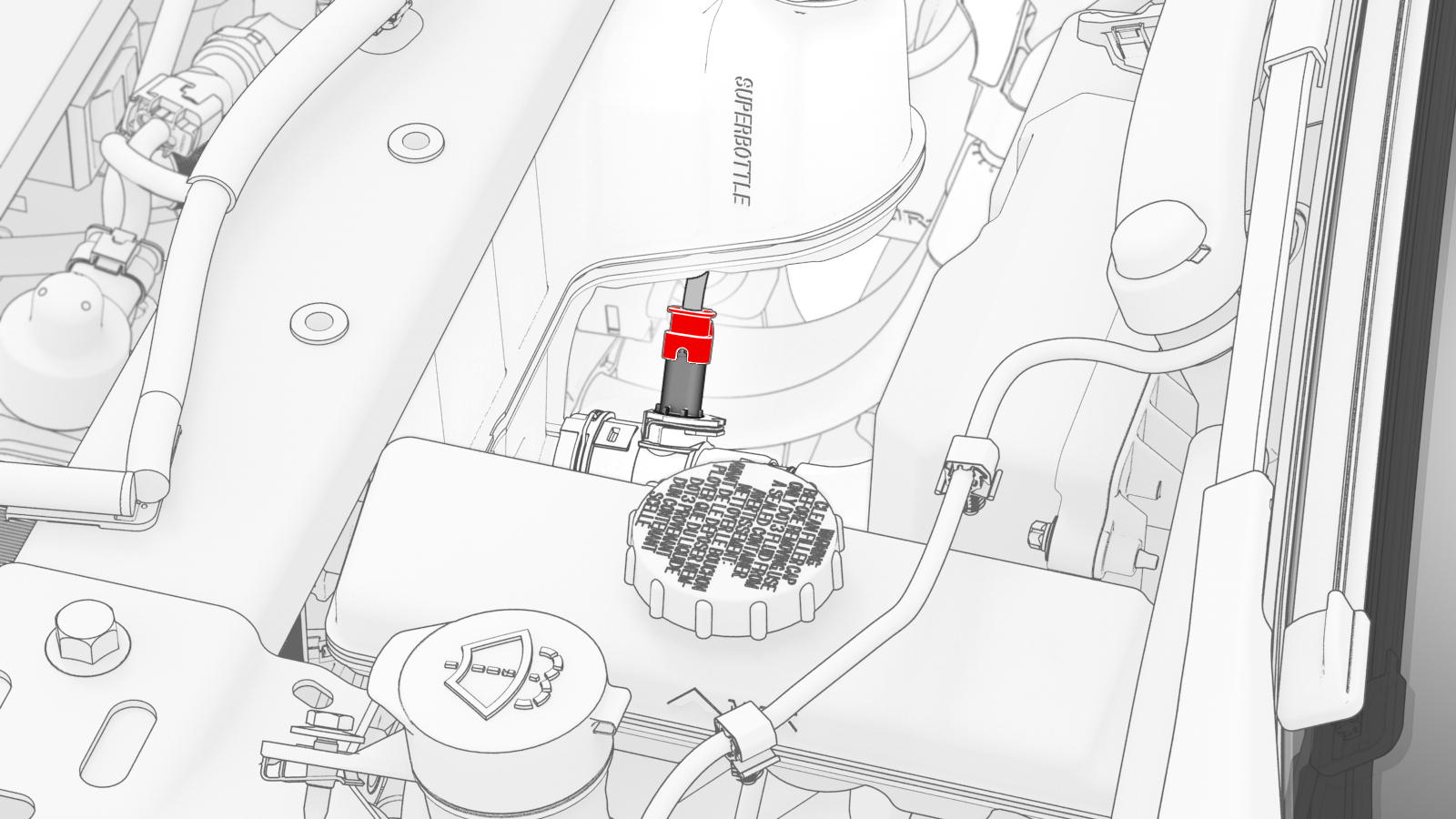
-
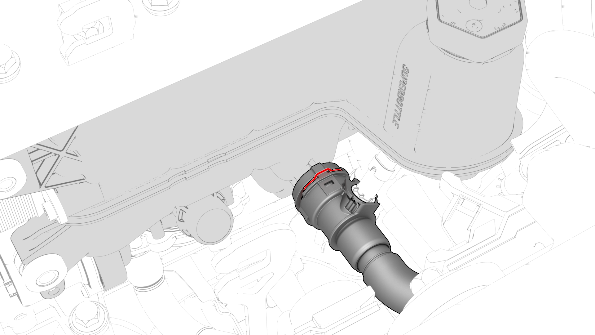
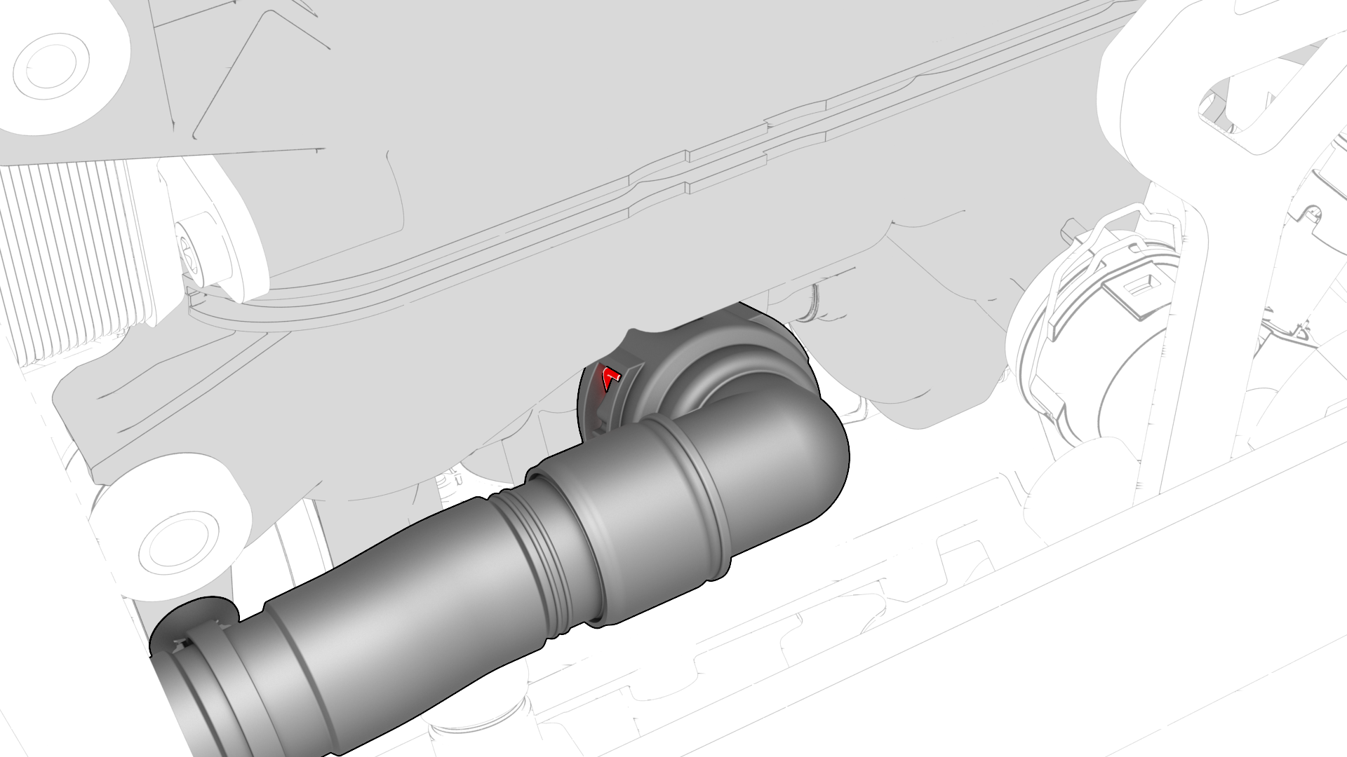
Release the clip and disconnect the powertrain pump-sill connector hose from the rear right of the superbottle.
-
Release the clip that attaches the suction/liquid lines to the superbottle.
-
Release the clip that attaches the electrical harness to the RH side of the superbottle.
-
Disconnect the electrical harness from the superbottle level sensor connector.
-
Release the clip and disconnect the battery return hose from the rear left of the superbottle.
Tip: Tilt the superbottle toward the front of the vehicle for better access.
-
Release the clip that attaches the battery return hose to the superbottle.
-
Release the clip that attaches the electrical harness to the lower LH side of the superbottle.
Tip: Lift the superbottle for better access.
-
Disconnect the electrical harness from the 5-way valve actuator connector.
Tip: Lift the superbottle for better access.
 Warning: Make sure that the refrigerant has fully recovered before continuing this procedure.
 -
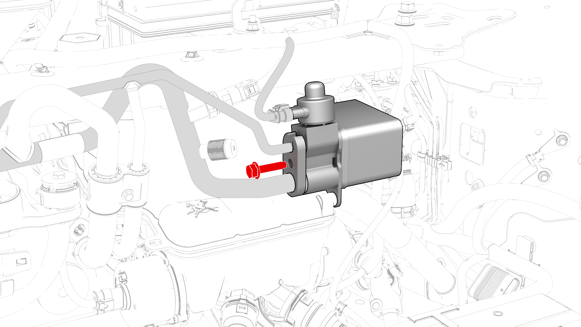
Remove the bolt that attaches the suction/liquid line to the chiller and EXV assembly, and then remove the line from the chiller and EXV assembly.
-
Remove the superbottle from the vehicle.
-
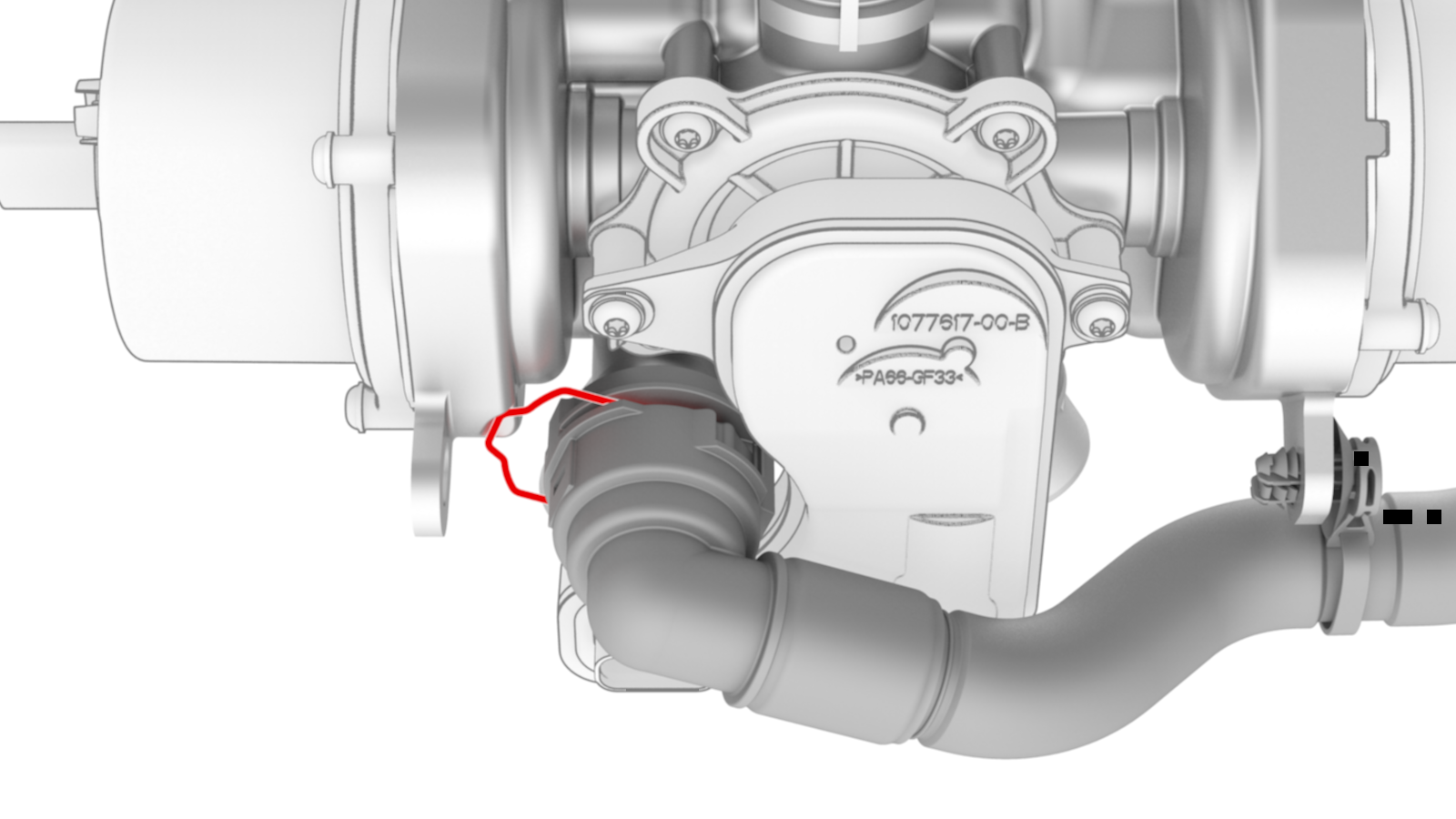
Release the clip that attaches the front drive unit heat exchanger-superbottle hose to the superbottle.
-
Release the clip and disconnect the front drive unit heat exchanger-superbottle hose from the superbottle.
| 1 | Remove the 2nd row lower seat cushion. See Seat Cushion - Lower - 2nd Row (Remove and Replace). | ||
| 2 | Remove the rear underhood apron. See Underhood Apron - Rear (Remove and Replace). | ||
| 3 | Remove the cabin intake duct. See Duct - Cabin Intake (Remove and Replace). | ||
| 4 | Remove the underhood storage unit. See Underhood Storage Unit (Remove and Replace). | ||
| 5 | Recover the A/C refrigerant. See A/C Refrigerant (Recovery and Recharge). Note: Recover the refrigerant while continuing this procedure.
| ||
| 6 | Remove the superbottle cap. | |
| 7 | Disconnect 12V power. See 12V Power (Disconnect and Connect). | ||
| 8 | Remove the 12V auxiliary battery. See Battery - 12V (Remove and Replace). | ||
| 9 | Remove the shock tower brace. See Brace - Shock Tower (Remove and Replace). Note: Do not separate the compressor body bracket from the strut tower brace.
| ||
| 10 | Remove the front aero shield. See Panel - Aero Shield - Front (Remove and Replace). | ||
| 11 | Partially lower the vehicle, and then position a coolant drain container underneath the RH front side of the vehicle. | ||
| 12 | Install a foldable funnel underneath the heat exchanger, as shown. Note: Make sure the foldable funnel covers the front drive unit 12V connector, steering rack, and is positioned to catch fluid from the heat exchanger coolant outlet.
| |
| 13 | Release the clip that connects the front drive unit heat exchanger-superbottle hose to the heat exchanger coolant outlet, and then drain the coolant into the coolant drain container. | |
| 14 | Plug the front drive unit heat exchanger-superbottle hose and the heat exchanger coolant outlet. | ||
| 15 | Release the clip and disconnect the radiator inlet hose from the front left of the superbottle. | |
| 16 | Release the clip and disconnect the radiator outlet hose from the front right of the superbottle. | |
| 17 | Disconnect the electrical harness from the chiller and EXV assembly hose coolant temperature sensor connector. | |
| 18 | Release the clip and disconnect the coolant hose from the chiller and EXV assembly. | |
| 19 | Disconnect the electrical harness from the HV battery coolant pump connector. | |
| 20 | Disconnect the electrical harness from the powertrain coolant pump connector. | |
| 21 | Disconnect the electrical harness from the powertrain pump to sill hose coolant temperature sensor connector.Tip: Tilt the superbottle toward the front of the vehicle for better access. | |
| 22 | Release the clip and disconnect the powertrain pump-sill connector hose from the rear right of the superbottle. | |
| 23 | Release the clip that attaches the suction/liquid lines to the superbottle. | |
| 24 | Release the clip that attaches the electrical harness to the RH side of the superbottle. | |
| 25 | Disconnect the electrical harness from the superbottle level sensor connector. | |
| 26 | Release the clip and disconnect the battery return hose from the rear left of the superbottle.Tip: Tilt the superbottle toward the front of the vehicle for better access. | |
| 27 | Release the clip that attaches the battery return hose to the superbottle. | |
| 28 | Release the clip that attaches the electrical harness to the lower LH side of the superbottle.Tip: Lift the superbottle for better access. | |
| 29 | Disconnect the electrical harness from the 5-way valve actuator connector.Tip: Lift the superbottle for better access.Warning: Make sure that the refrigerant has fully recovered before continuing this procedure. | |
| 30 | Remove the bolt that attaches the suction/liquid line to the chiller and EXV assembly, and then remove the line from the chiller and EXV assembly. | |
| 31 | Remove and discard the o-rings from the suction/liquid line fitting. | ||
| 32 | Remove the superbottle from the vehicle. | |
| 33 | Release the clip that attaches the front drive unit heat exchanger-superbottle hose to the superbottle. | |
| 34 | Release the clip and disconnect the front drive unit heat exchanger-superbottle hose from the superbottle. |
Install
-
Connect the front drive unit heat exchanger-superbottle hose to the superbottle, and then install the clip.
-
Install the clip that attaches the front drive unit heat exchanger-superbottle hose to the superbottle.
-
Position the superbottle in the vehicle.
-
Connect the electrical harness to the 5-way valve actuator connector.
-
Install the clip that attaches the electrical harness to the lower LH side of the superbottle.
-
Install the clip that attaches the battery return hose to the superbottle.
-
Connect the battery return hose to the superbottle, and then install the clip.
-
Connect the electrical harness to the superbottle level sensor connector.
-
Install the clip that attaches the electrical harness to the RH side of the superbottle.
-
Install the clip that attaches the suction/liquid lines to the superbottle.
-
Connect the powertrain pump-sill connector hose to the superbottle, and then install the clip.
-
Connect the electrical harness to the powertrain pump-sill connector hose coolant temperature sensor.
-
Connect the electrical harness to the powertrain coolant pump connector.
-
Connect the electrical harness to the HV battery coolant pump connector.
-
Connect the coolant hose to the chiller and EXV assembly, and then install the clip.
Note: Perform a push-pull test on the hose to verify that the hose is fully attached.
-
Connect the electrical harness to the chiller and EXV assembly hose coolant temperature sensor.
-
Connect the radiator outlet hose to the front right of the superbottle, and then install the clip.
-
Connect the radiator inlet hose to the front left of the superbottle, and then install the clip.
-
Connect the front drive unit heat exchanger-superbottle hose to the heat exchanger, and then install the clip.
-
Install new o-rings onto the suction/liquid line fitting, install the suction/liquid line fitting into the chiller and EXV assembly, and then install the bolt that attaches the suction/liquid line to the chiller and EXV assembly.
 Torque 5.5 Nm
| 1 | Connect the front drive unit heat exchanger-superbottle hose to the superbottle, and then install the clip. | |
| 2 | Install the clip that attaches the front drive unit heat exchanger-superbottle hose to the superbottle. | |
| 3 | Position the superbottle in the vehicle. | |
| 4 | Connect the electrical harness to the 5-way valve actuator connector. | |
| 5 | Install the clip that attaches the electrical harness to the lower LH side of the superbottle. | |
| 6 | Install the clip that attaches the battery return hose to the superbottle. | |
| 7 | Connect the battery return hose to the superbottle, and then install the clip. | |
| 8 | Connect the electrical harness to the superbottle level sensor connector. | |
| 9 | Install the clip that attaches the electrical harness to the RH side of the superbottle. | |
| 10 | Install the clip that attaches the suction/liquid lines to the superbottle. | |
| 11 | Connect the powertrain pump-sill connector hose to the superbottle, and then install the clip. | |
| 12 | Connect the electrical harness to the powertrain pump-sill connector hose coolant temperature sensor. | |
| 13 | Connect the electrical harness to the powertrain coolant pump connector. | |
| 14 | Connect the electrical harness to the HV battery coolant pump connector. | |
| 15 | Connect the coolant hose to the chiller and EXV assembly, and then install the clip. Note: Perform a push-pull test on the hose to verify that the hose is fully attached.
| |
| 16 | Connect the electrical harness to the chiller and EXV assembly hose coolant temperature sensor. | |
| 17 | Connect the radiator outlet hose to the front right of the superbottle, and then install the clip. | |
| 18 | Connect the radiator inlet hose to the front left of the superbottle, and then install the clip. | |
| 19 | Remove the plugs from the front drive unit heat exchanger-superbottle hose and coolant port. | ||
| 20 | Connect the front drive unit heat exchanger-superbottle hose to the heat exchanger, and then install the clip. | |
| 21 | Remove the coolant drain container from underneath the vehicle, and then install the front aero shield panel. See Panel - Aero Shield - Front (Remove and Replace). | ||
| 22 | Install new o-rings onto the suction/liquid line fitting, install the suction/liquid line fitting into the chiller and EXV assembly, and then install the bolt that attaches the suction/liquid line to the chiller and EXV assembly. Torque 5.5 Nm | |
| 23 | Install the shock tower brace. See Brace - Shock Tower (Remove and Replace). | ||
| 24 | Connect the A/C lines to the vehicle, and then initiate an A/C vacuum and leak test. | ||
| 25 | Install the 12V battery. See Battery - 12V (Remove and Replace). | ||
| 26 | When the A/C vacuum and leak test is complete, recharge the refrigerant. See A/C Refrigerant (Recovery and Recharge). | ||
| 27 | Connect 12V power. See 12V Power (Disconnect and Connect). | ||
| 28 | Perform a cooling system vacuum refill. See Cooling System (Vacuum Refill). | ||
| 29 | Connect a charge cable to the vehicle. | ||
| 30 | Connect a laptop with Toolbox to the vehicle. | ||
| 31 | Using Toolbox, run the 5-way valve actuator self-test, "TEST-SELF_VCFRONT_X_FIVE-WAY-VALVE." Note: This Toolbox routine tests and calibrates the 5-way valve actuator.
| ||
| 32 | In Toolbox, click the play button next to "TEST-SELF_VCFRONT_X_THERMAL-PERFORMANCE", and then select Run. | ||
| 33 | When the thermal performance test is complete, disconnect the charge cable from the vehicle. | ||
| 34 | Disconnect the laptop from the vehicle. | ||
| 35 | Install the underhood storage unit. See Underhood Storage Unit (Remove and Replace). | ||
| 36 | Install the cabin intake duct. See Duct - Cabin Intake (Remove and Replace). | ||
| 37 | Install the rear underhood apron. See Underhood Apron - Rear (Remove and Replace). | ||
| 38 | Install the 2nd row lower seat cushion. See Seat Cushion - Lower - 2nd Row (Remove and Replace). |