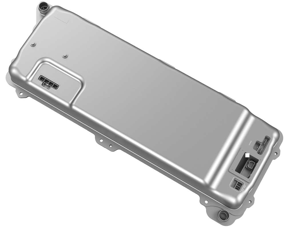
Power Conversion System (Remove and Replace)
Correction code 1630100216301002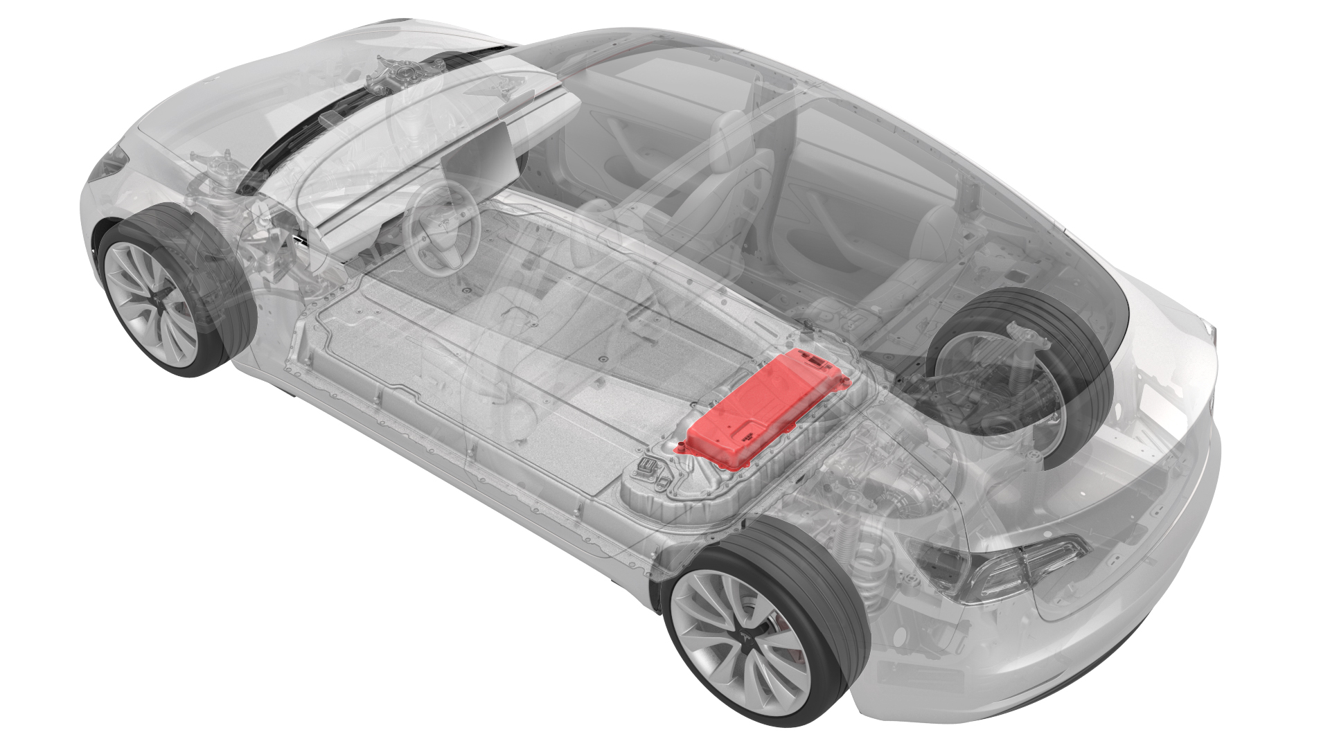
- 1111868-00-B Connector Removal, Coolant, PCS, M3
- 1135762-00-AKit, Svc Plug, Cooling Hose, Model 3
- 1114917-00-ATool, Vacuum Cup, 3" x 6" (Qty 2)
- 1076927-00-A Resistance meter, microohm, Hioki RM 3548
SPECIAL TOOLS
Connector Removal, Coolant, PCS, M3 (1111868-00-B) |
Kit, Svc Plug, Cooling Hose, Model 3 (1135762-00-A) |
Tool, Vacuum Cup, 3" x 6" (Qty 2) (1114917-00-A) |
Resistance meter, microohm, Hioki RM 3548 (1076927-00-A) |
 Warning:
Only technicians who have been trained in High Voltage Awareness are permitted to perform this procedure. Proper personal protective equipment (PPE) and insulating HV gloves with a minimum rating of class 0 (1000V) must be worn at all times a high voltage cable, busbar, or fitting is handled. Refer to Tech Note TN-15-92-003, "High Voltage Awareness Care Points" for additional safety information.
Remove
-
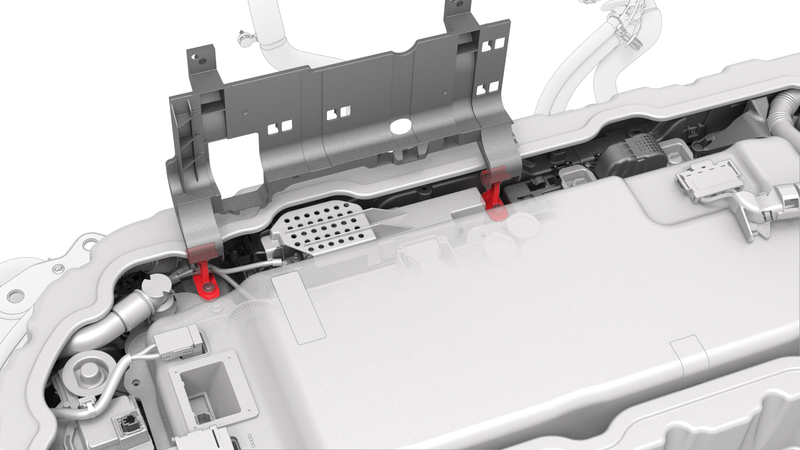
Release the clips (x5) that attach the electrical harness to the hinge tray.
-
Raise the hinge tray vertically, pull up on the tray at each hinge, and then remove the tray from the vehicle.
-
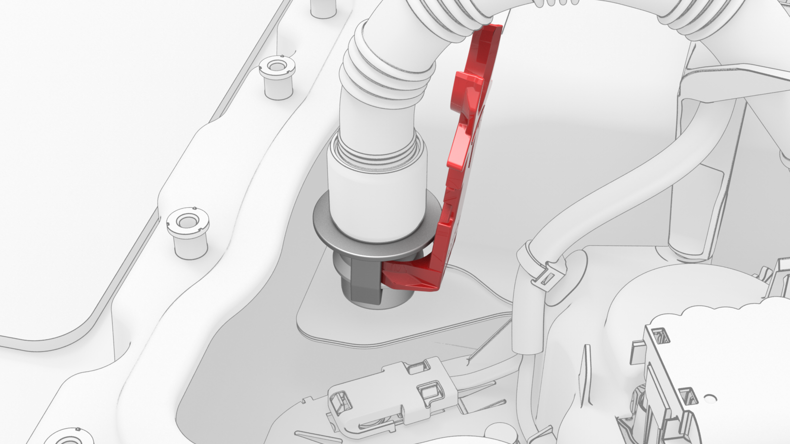
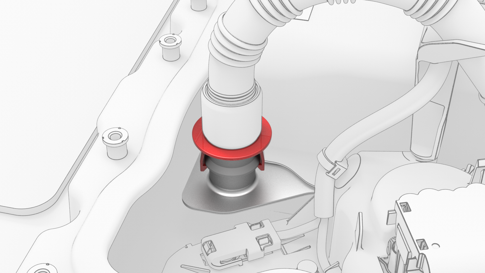
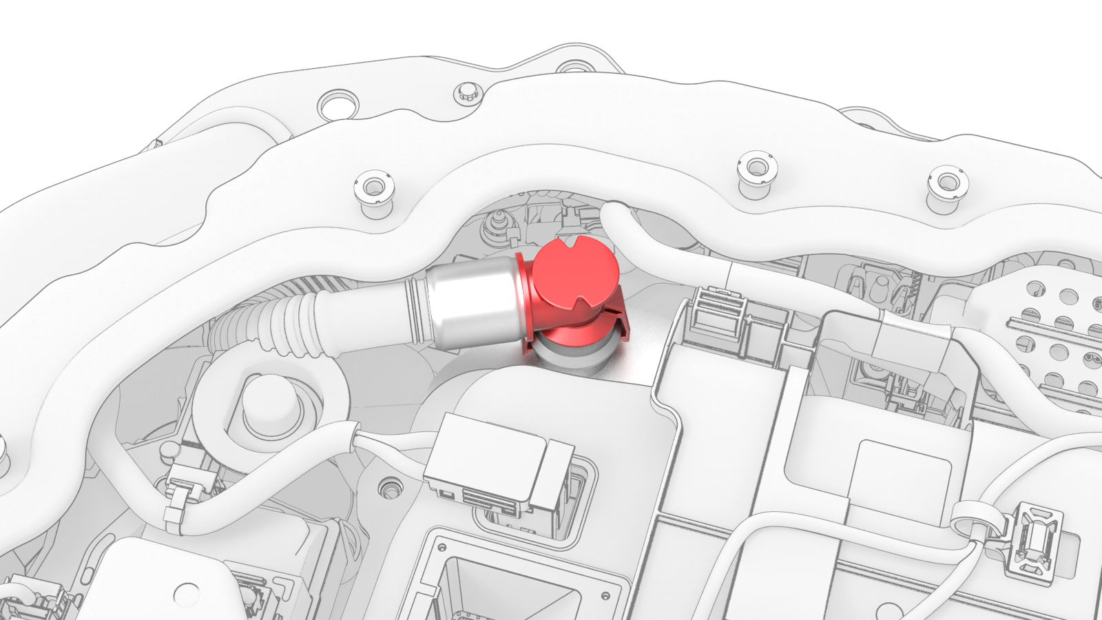
Use the coolant connector removal tool to release the clips that attach the coolant input tube to the power conversion system, and remove the tube from the power conversion system. See Tube - Input - Coolant - Power Conversion System (Remove and Replace).
-
Use the coolant connector removal tool to release the clips that attach the coolant output tube to the power conversion system, and remove the tube from the power conversion system. See Tube - Output - Coolant - Power Conversion System (Remove and Replace).
-
Wipe around the power conversion system coolant ports, wipe the ends of the coolant tubes, and wipe up any spilled coolant.
 Caution:Spilled coolant can create an electrical path.
 -
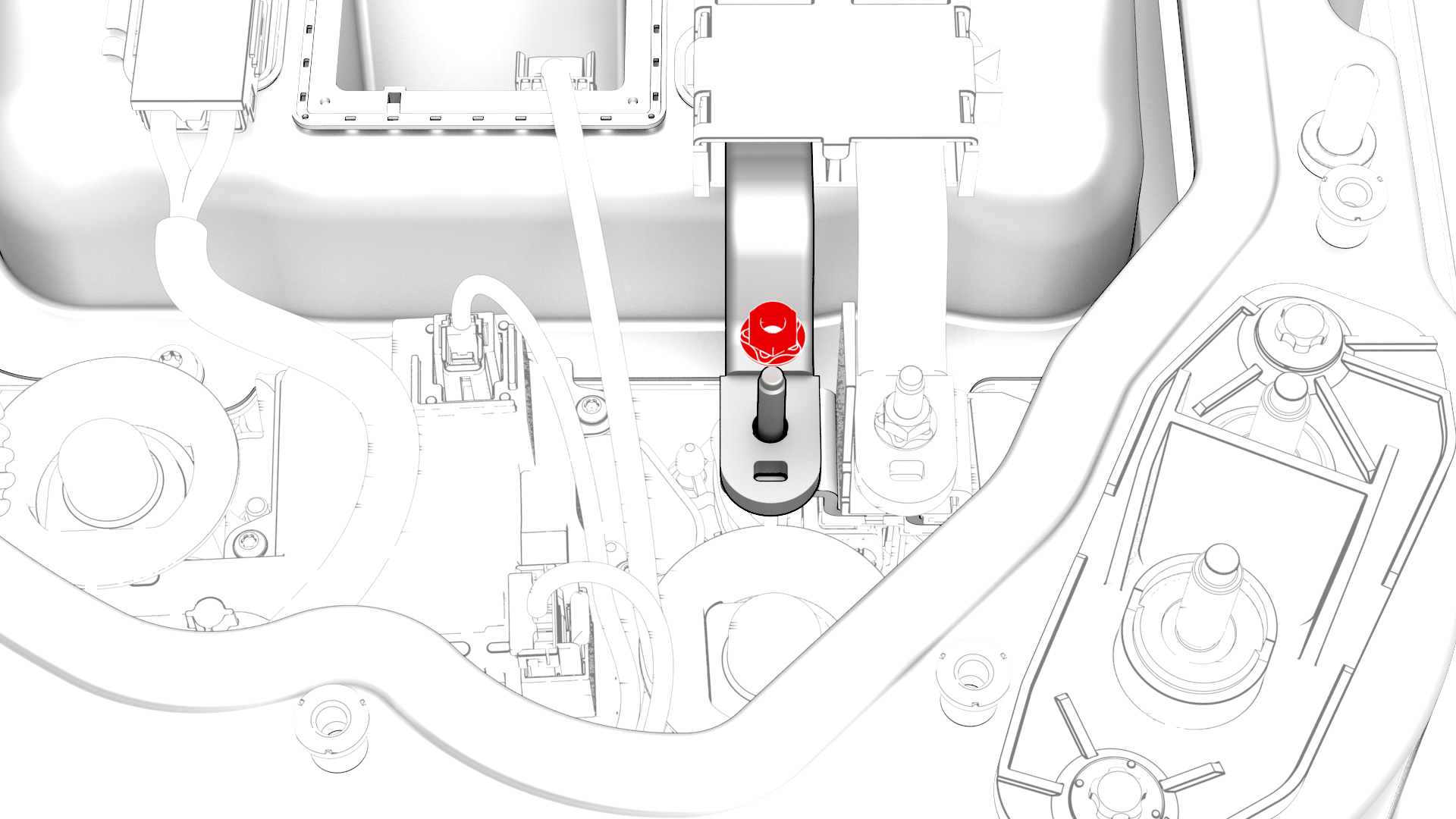
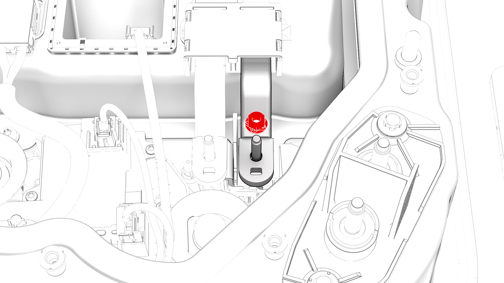
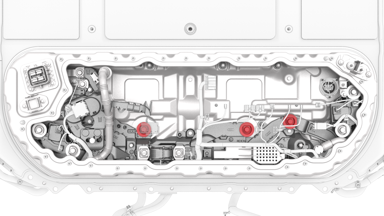
Remove the nut that attaches the positive terminal of the DCDC harness to the positive DCDC passthrough busbar.
-
Remove the nut that attaches the negative terminal of the DCDC harness to the negative DCDC passthrough busbar.
-
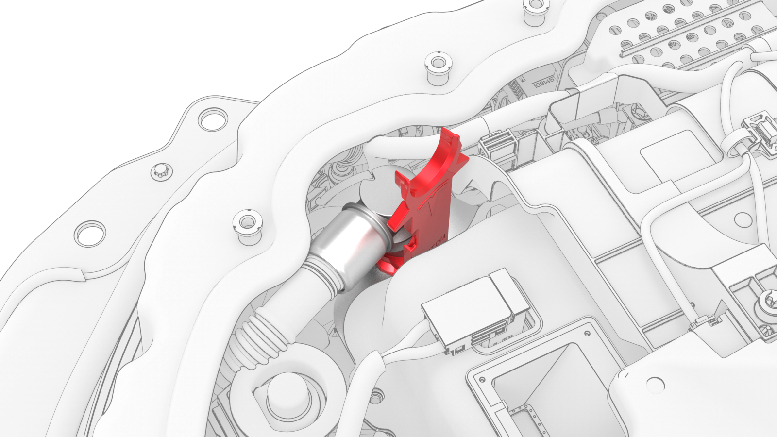
Release the clip and disconnect the DCDC harness from the power conversion system.
-
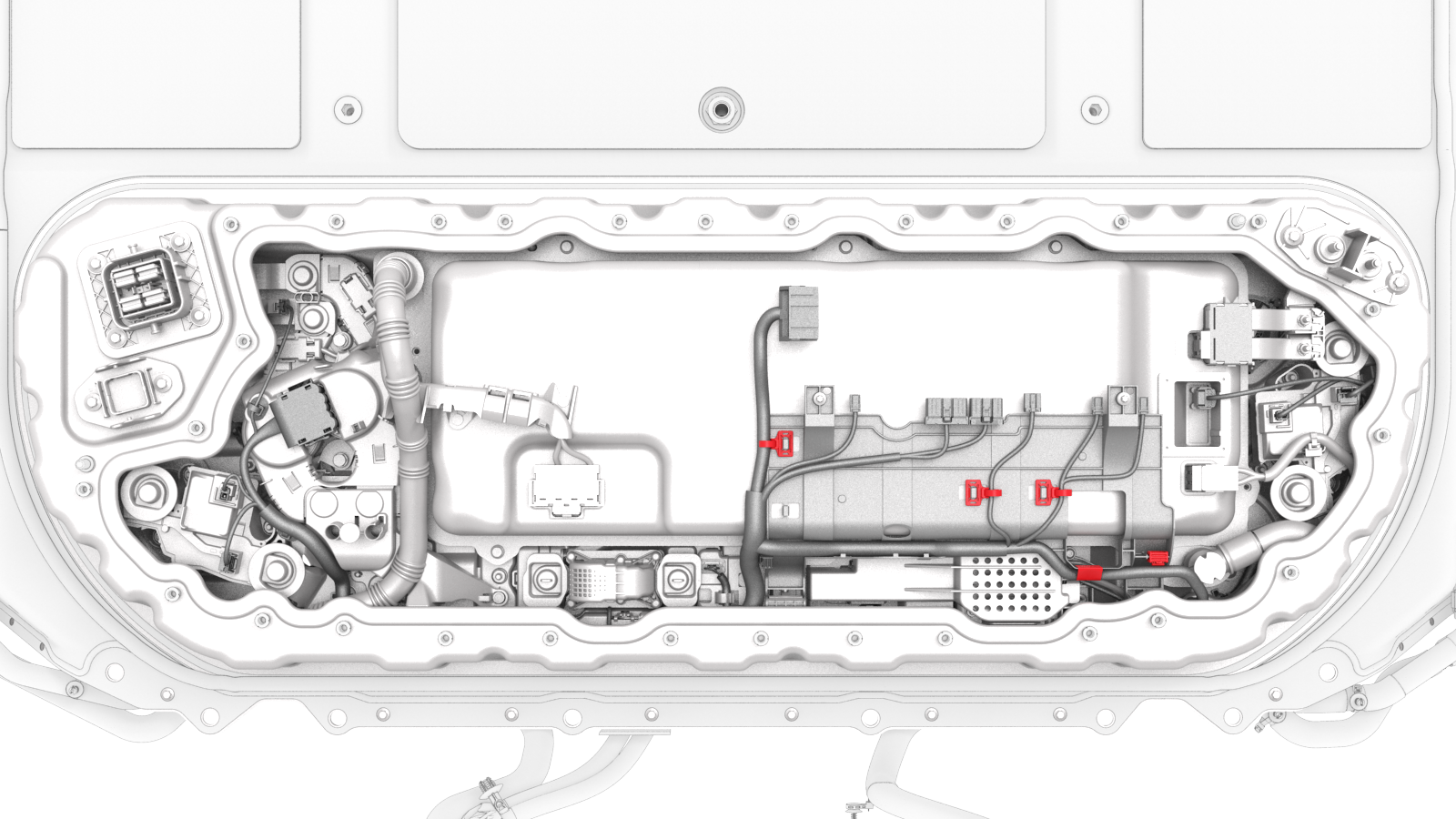
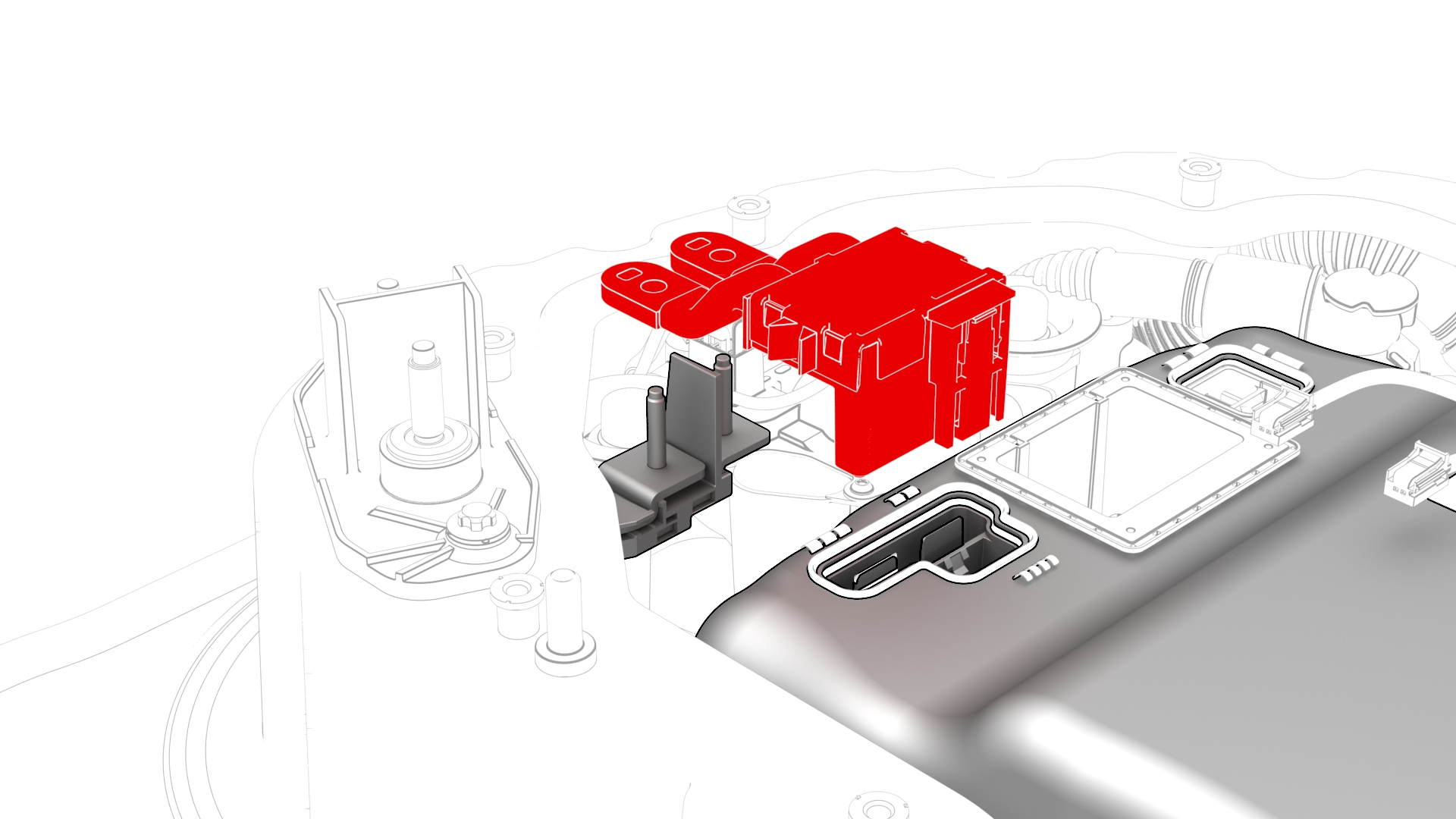
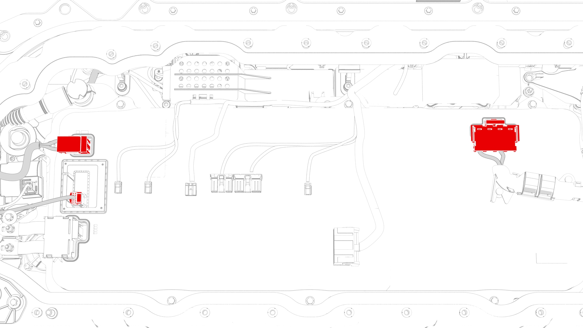
Disconnect the LV connector, the DC bus HV connector, and the HV battery AC inlet harness connector from the power conversion system.
-
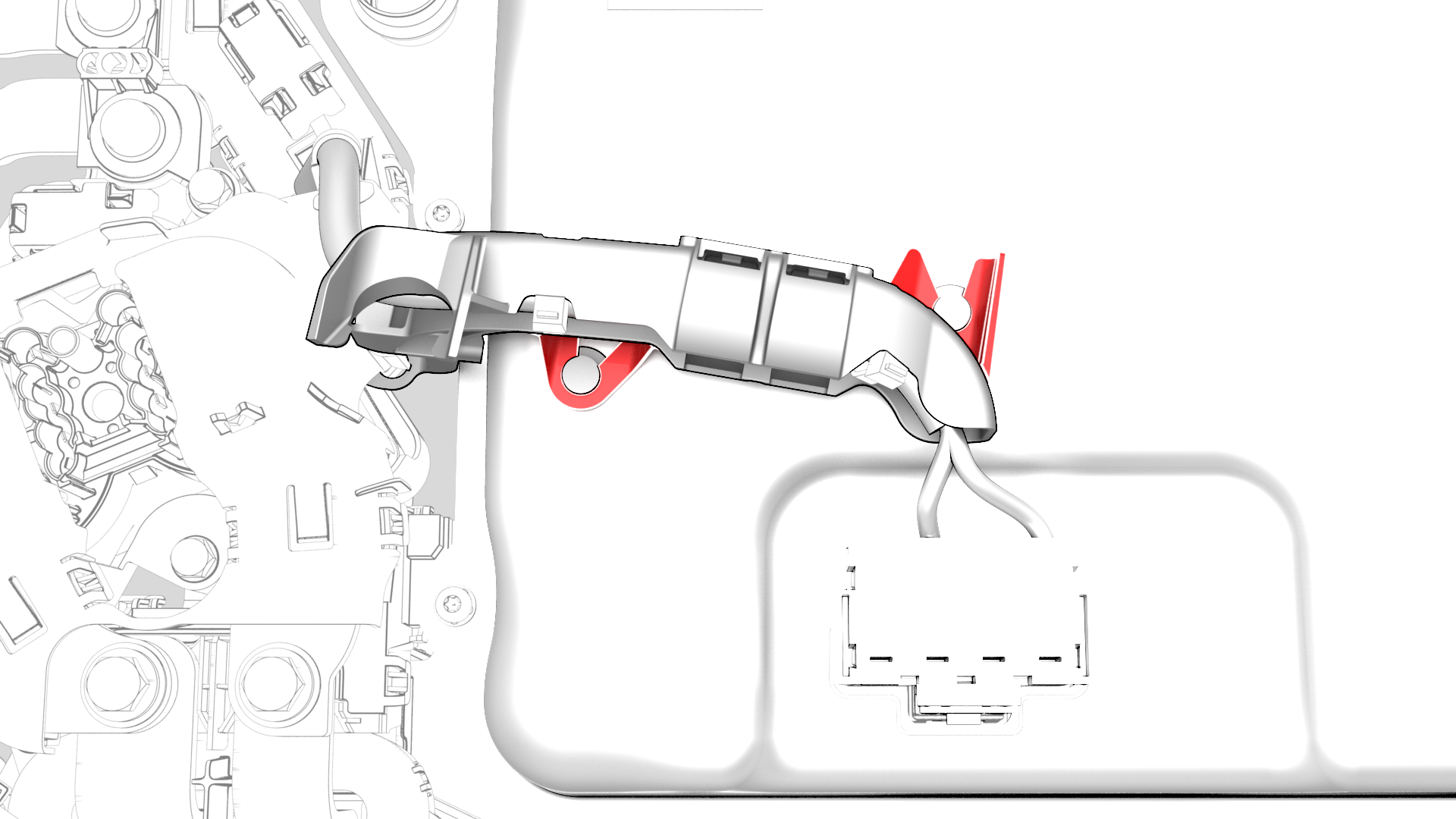
Release the clips that attach the HV battery AC inlet harness to the power conversion system, and move the harness aside.
-
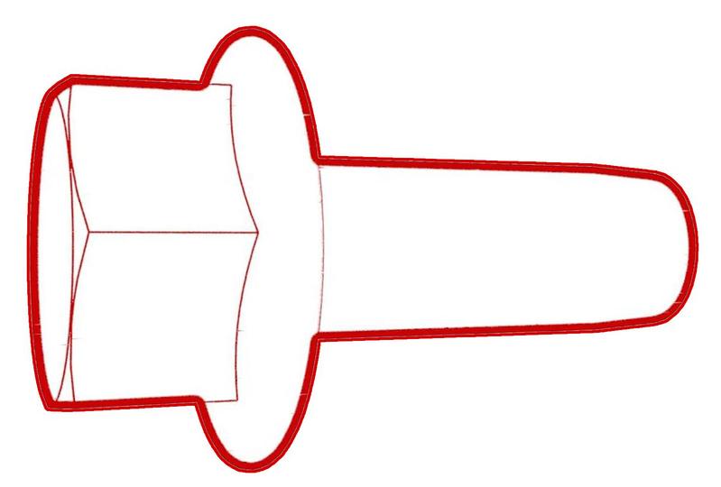
Remove the hex head bolts that attach the power conversion system to the HV battery.
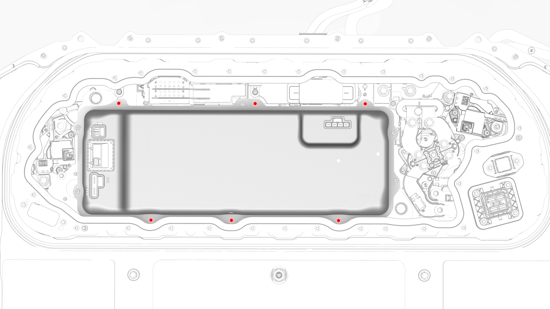 Vehicles Made Before 9/11/18 - 6-Bolts
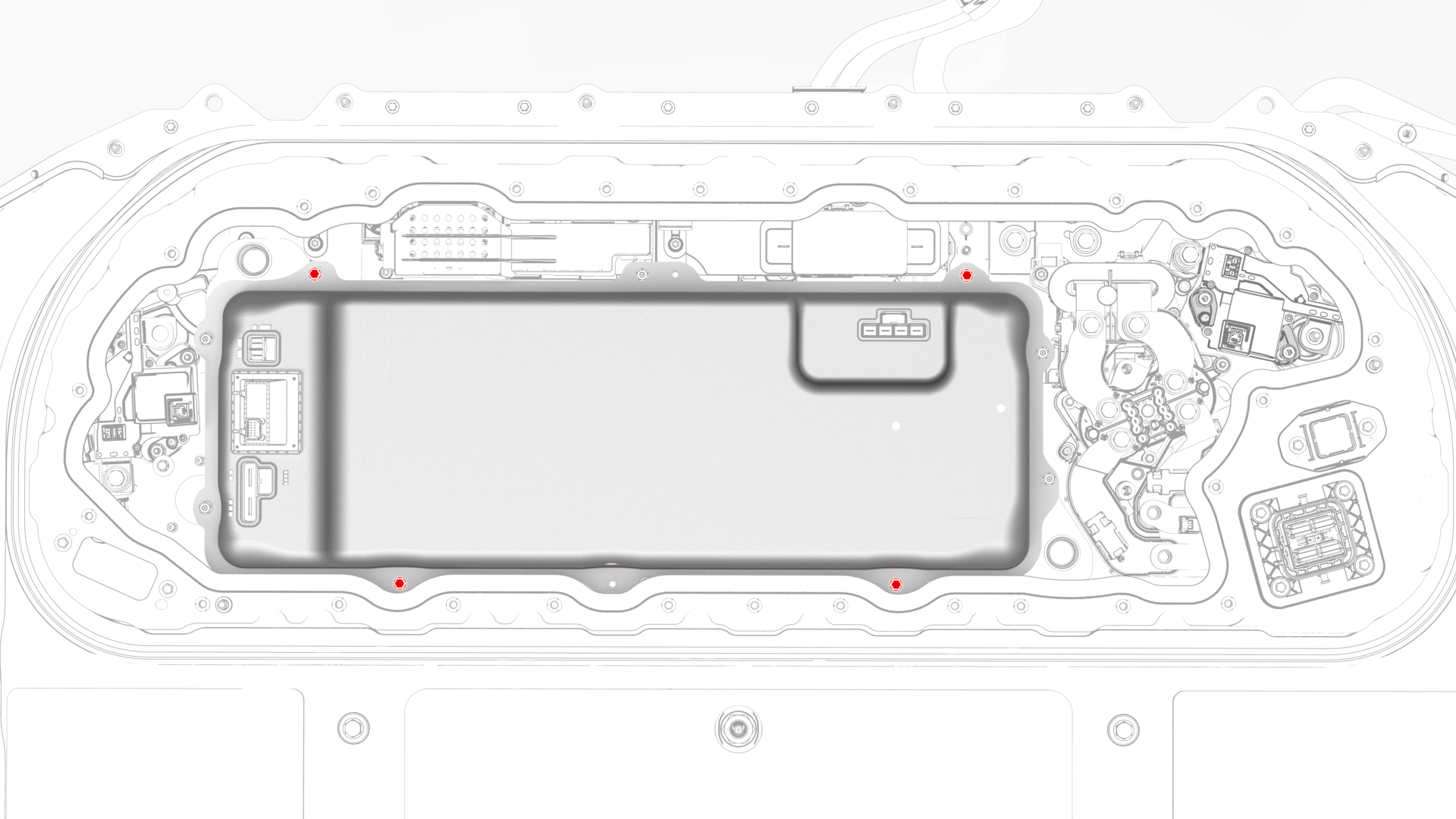 Vehicles Made On 9/11/18 And Thereafter - 4-Bolts
 -
With assistance, use suction cups to lift the power conversion system out of the penthouse.
Caution:Keep the power conversion system level as you lift it, to prevent spilling coolant.
-
Visually inspect the area from which the power conversion system was removed.
- If any of the insulators (x3) are missing from the busbar bolt heads, install the insulators now.
- If all of the insulators are installed, continue to the next step.
| 1 | Drain the coolant from the power conversion system. See Penthouse Coolant (Drain and Refill). | ||
| 2 | Remove the pyrotechnic battery disconnect from the penthouse. See Pyrotechnic Battery Disconnect (Remove and Replace). | ||
| 3 | Remove the high voltage controller. See Controller - High Voltage (Remove and Replace). | ||
| 4 | Release the clips (x5) that attach the electrical harness to the hinge tray. | |
| 5 | Raise the hinge tray vertically, pull up on the tray at each hinge, and then remove the tray from the vehicle. | |
| 6 | Cut a slit halfway through 2 absorbent pads and surround each power conversion system coolant tube fitting with a pad. | ||
| 7 | Use the coolant connector removal tool to release the clips that attach the coolant input tube to the power conversion system, and remove the tube from the power conversion system. See Tube - Input - Coolant - Power Conversion System (Remove and Replace). | |
| 8 | Install plugs into the coolant input port of the power conversion system and the open end of the coolant input tube. | ||
| 9 | Use the coolant connector removal tool to release the clips that attach the coolant output tube to the power conversion system, and remove the tube from the power conversion system. See Tube - Output - Coolant - Power Conversion System (Remove and Replace). | |
| 10 | Install plugs into the coolant output port of the power conversion system and the open end of the coolant output tube. | ||
| 11 | Wipe around the power conversion system coolant ports, wipe the ends of the coolant tubes, and wipe up any spilled coolant. Caution: Spilled coolant can create an electrical path.
| ||
| 12 | Remove the nut that attaches the positive terminal of the DCDC harness to the positive DCDC passthrough busbar. | |
| 13 | Remove the nut that attaches the negative terminal of the DCDC harness to the negative DCDC passthrough busbar. | |
| 14 | Release the clip and disconnect the DCDC harness from the power conversion system. | |
| 15 | Disconnect the LV connector, the DC bus HV connector, and the HV battery AC inlet harness connector from the power conversion system. | |
| 16 | Release the clips that attach the HV battery AC inlet harness to the power conversion system, and move the harness aside. | |
Vehicles Made Before 9/11/18 - 6-Bolts
Vehicles Made On 9/11/18 And Thereafter - 4-Bolts
| 17 | Remove the hex head bolts that attach the power conversion system to the HV battery. | |
| 18 | With assistance, use suction cups to lift the power conversion system out of the penthouse. Caution: Keep the power conversion system level as you lift it, to prevent spilling coolant.
| ||
| 19 | Visually inspect the area from which the power conversion system was removed.
| |
| 20 | Remove the plugs from the power conversion system, drain the coolant into a coolant drain, and then replace the plugs. | ||
| 21 | Remove the absorbent pads from around the power conversion system coolant ports. |
Install
-
Inspect the area of the penthouse where the power conversion system will install, and wipe up any spilled coolant.
Caution:Spilled coolant can create an electrical path.
-
Install the hex head bolts that attach the power conversion system to the HV battery, and then mark the bolts with a paint pen after they are torqued.
 Torque 6-Bolt Power Conversion System to 6 Nm
- Torque 4-Bolt Power Conversion System to 18 Nm
Vehicles Made Before 9/11/18 - 6-Bolts
Vehicles Made On 9/11/18 And Thereafter - 4-Bolts -
Fasten the clips that attach the HV battery AC inlet harness to the power conversion system.
-
Connect the HV battery AC inlet harness connector, the DC bus HV connector, and the LV connector to the power conversion system.
-
Connect the DCDC harness to the power conversion system, and then fasten the clip that attaches the DCDC harness to the power conversion system.
-
Install the nut that attaches the negative terminal of the DCDC harness to the negative DCDC passthrough busbar, and then mark the nut with a paint pen after it is torqued.
 Torque 4.5 Nm
 -
Install the nut that attaches the positive terminal of the DCDC harness to the positive DCDC passthrough busbar, and then mark the nut with a paint pen after it is torqued.Torque 4.5 Nm
-
Use the Hioki resistance meter to measure the resistance between the positive joint of the DCDC harness and the positive terminal of the 12V DCDC passthrough.
Note: The maximum acceptable resistance is 0.100 mΩ (100 μΩ). If the resistance is above this value, escalate a Toolbox session, as appropriate.
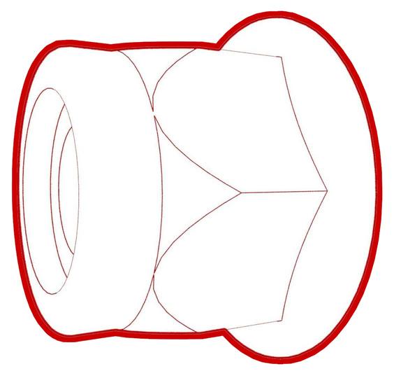
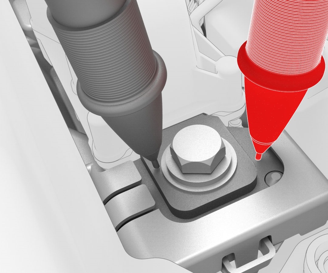 Generic Measurement - Actual busbars and fasteners might appear different
 -
Use the Hioki resistance meter to measure the resistance between the negative joint of the DCDC harness and the negative terminal of the 12V DCDC passthrough.
Note: The maximum acceptable resistance is 0.100 mΩ (100 μΩ). If the resistance is above this value, escalate a Toolbox session, as appropriate.
Generic Measurement - Actual busbars and fasteners might appear different
-
Connect the coolant output tube to the power conversion system. See Tube - Output - Coolant - Power Conversion System (Remove and Replace).
Caution:Make sure that the coolant output tube is securely connected by firmly pressing down on it, verify that both clips have fully engaged the barb on the power conversion system, and then pull up on the fitting to check retention.
-
Wipe up any spilled coolant.
Caution:Spilled coolant can create an electrical path.
-
Connect the coolant input tube to the power conversion system. See Tube - Input - Coolant - Power Conversion System (Remove and Replace).
Caution:Make sure that the coolant input tube is securely connected by firmly pressing down on it, verify that both clips have fully engaged the barb on the power conversion system, and then pull up on the fitting to check retention.
-
Wipe up any spilled coolant.
Caution:Spilled coolant can create an electrical path.
-
Connect the 12V auxiliary battery negative terminal only.
 Torque 6 NmCaution:Do not follow the procedure to connect 12V power at this time.
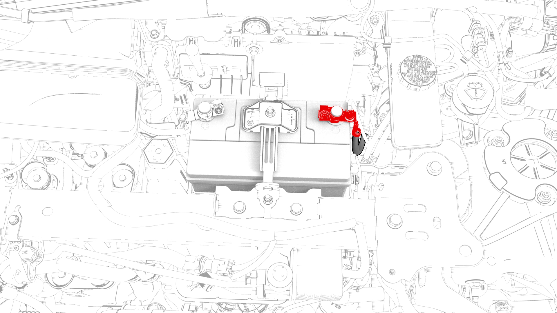
-
Disconnect the 12V auxiliary battery negative terminal.
-
Install the hinge tray vertically onto the hinges, press down on the tray at each hinge so that the tray attaches into the hinges, and then lower the tray.
-
Fasten the clips that attach the harness to the hinge tray.
| 1 | Consider your first step.
| ||
| 2 | Remove the shipping plugs from the replacement power conversion system. | ||
| 3 | Tilt the power conversion system and drain the shipping water into a coolant drain. | ||
| 4 | Replace the shipping plugs. Note: Do not remove the plugs again until instructed.
| ||
| 5 | Wipe the power conversion system dry. | ||
| 6 | Inspect the area of the penthouse where the power conversion system will install, and wipe up any spilled coolant. Caution: Spilled coolant can create an electrical path.
| ||
| 7 | With assistance, use suction cups to lift the power conversion system into the penthouse. | ||
Vehicles Made Before 9/11/18 - 6-Bolts
Vehicles Made On 9/11/18 And Thereafter - 4-Bolts
| 8 | Install the hex head bolts that attach the power conversion system to the HV battery, and then mark the bolts with a paint pen after they are torqued.
| |
| 9 | Fasten the clips that attach the HV battery AC inlet harness to the power conversion system. | |
| 10 | Connect the HV battery AC inlet harness connector, the DC bus HV connector, and the LV connector to the power conversion system. | |
| 11 | Connect the DCDC harness to the power conversion system, and then fasten the clip that attaches the DCDC harness to the power conversion system. | |
| 12 | Install the nut that attaches the negative terminal of the DCDC harness to the negative DCDC passthrough busbar, and then mark the nut with a paint pen after it is torqued. Torque 4.5 Nm | |
| 13 | Install the nut that attaches the positive terminal of the DCDC harness to the positive DCDC passthrough busbar, and then mark the nut with a paint pen after it is torqued. Torque 4.5 Nm | |
Generic Measurement - Actual busbars and fasteners might appear different
| 14 | Use the Hioki resistance meter to measure the resistance between the positive joint of the DCDC harness and the positive terminal of the 12V DCDC passthrough. Note: The maximum acceptable resistance is 0.100 mΩ (100 μΩ). If the resistance is above this value, escalate a Toolbox session, as appropriate.
| |
Generic Measurement - Actual busbars and fasteners might appear different
| 15 | Use the Hioki resistance meter to measure the resistance between the negative joint of the DCDC harness and the negative terminal of the 12V DCDC passthrough. Note: The maximum acceptable resistance is 0.100 mΩ (100 μΩ). If the resistance is above this value, escalate a Toolbox session, as appropriate.
| |
| 16 | Cut a slit halfway through 2 absorbent pads and surround each power conversion system coolant tube fitting with a pad. | ||
| 17 | Lubricate the coolant output tube and coolant input tube o-rings with Silaramic lubricant. | ||
| 18 | Remove the plugs from the coolant output port of the power conversion system and coolant output tube. | ||
| 19 | Connect the coolant output tube to the power conversion system. See Tube - Output - Coolant - Power Conversion System (Remove and Replace). Caution: Make sure that the coolant output tube is securely connected by firmly pressing down on it, verify that both clips have fully engaged the barb on the power conversion system, and then pull up on the fitting to check retention.
| |
| 20 | Wipe up any spilled coolant. Caution: Spilled coolant can create an electrical path.
| ||
| 21 | Remove the plugs from the coolant input port of the power conversion system and the coolant input tube. | ||
| 22 | Connect the coolant input tube to the power conversion system. See Tube - Input - Coolant - Power Conversion System (Remove and Replace). Caution: Make sure that the coolant input tube is securely connected by firmly pressing down on it, verify that both clips have fully engaged the barb on the power conversion system, and then pull up on the fitting to check retention.
| |
| 23 | Wipe up any spilled coolant. Caution: Spilled coolant can create an electrical path.
| ||
| 24 | Perform a penthouse coolant leak test. See Penthouse Coolant Leak Test. | ||
| 25 | Connect the 12V auxiliary battery negative terminal only. Torque 6 Nm Caution: Do not follow the procedure to connect 12V power at this time.
| |
| 26 | Connect a 12V charger to the 12V auxiliary battery terminals. | ||
| 27 | Refill the coolant. See Penthouse Coolant (Drain and Refill). | ||
| 28 | On the touchscreen, touch . | ||
| 29 | Disconnect the 12V charger from the 12V auxiliary battery terminals. | ||
| 30 | Disconnect the 12V auxiliary battery negative terminal. | |
| 31 | Install the hinge tray vertically onto the hinges, press down on the tray at each hinge so that the tray attaches into the hinges, and then lower the tray. | |
| 32 | Fasten the clips that attach the harness to the hinge tray. | |
| 33 | Install the high voltage controller. See Controller - High Voltage (Remove and Replace). | ||
| 34 | Install the pyrotechnic battery disconnect into the penthouse. See Pyrotechnic Battery Disconnect (Remove and Replace). | ||
| 35 | Flash the power conversion system with the latest firmware. |