Harness - AC Inlet - HV Battery (Remove and Replace)
Correction code 1630530216305302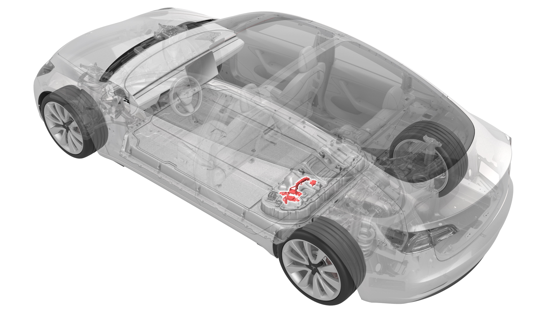
- 1076927-00-A Resistance meter, microohm, Hioki RM 3548
SPECIAL TOOLS
Resistance meter, microohm, Hioki RM 3548 (1076927-00-A) |
 Warning:
Only technicians who have been trained in High Voltage Awareness are permitted to perform this procedure. Proper personal protective equipment (PPE) and insulating HV gloves with a minimum rating of class 0 (1000V) must be worn at all times a high voltage cable, busbar, or fitting is handled. Refer to Tech Note TN-15-92-003, "High Voltage Awareness Care Points" for additional safety information.
Remove
-
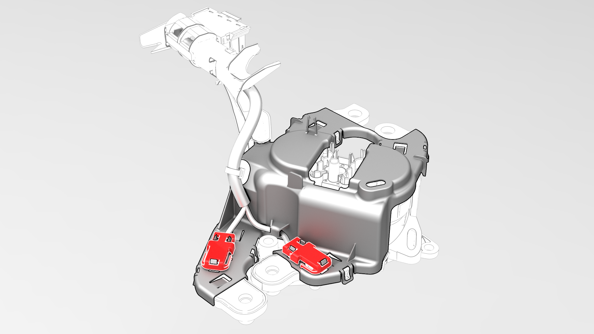
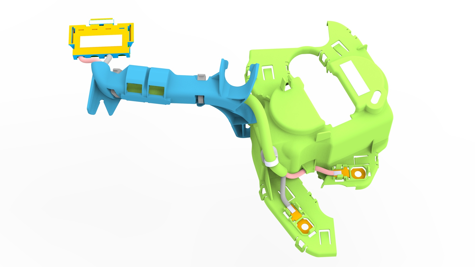
Release the clips that attach the AC inlet terminal covers over the negative and positive ring terminals, and then remove the covers.
-
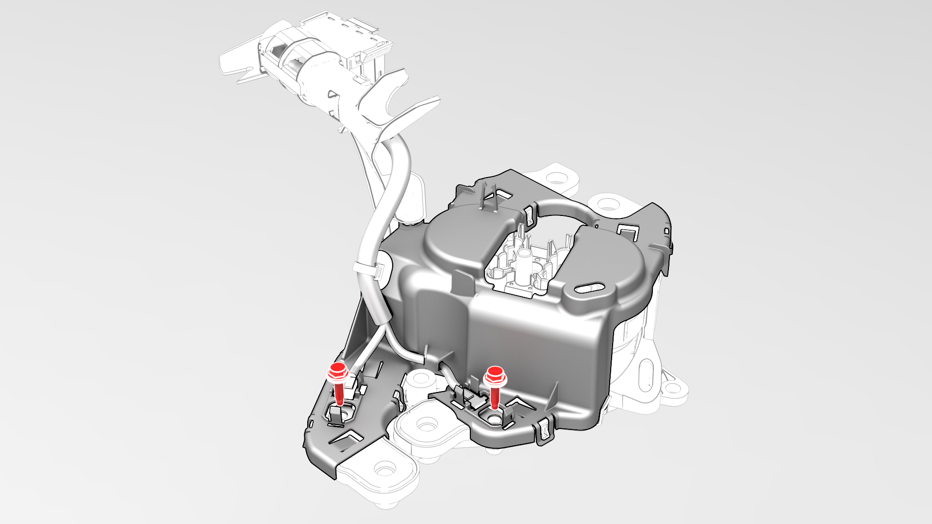
Remove and discard the bolts that attach the negative and positive ring terminals to the busbars.
i
-
Release the clips (x8) that attach the HV battery fast charge contactor cover to the HV battery fast charge contactor, and then remove the cover with the HV battery AC inlet harness from the contactor.
 Caution:The cover is a one-time use as the clips are fragile and break easily.
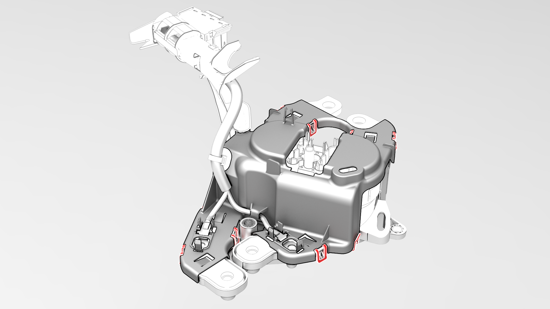
| 1 | Remove the HV battery fast charge contactor. See Contactor - Fast Charge - HV Battery (Remove and Replace). | ||
| 2 | Release the clips that attach the AC inlet terminal covers over the negative and positive ring terminals, and then remove the covers. | |
i | 3 | Remove and discard the bolts that attach the negative and positive ring terminals to the busbars. | |
| 4 | Release the clips (x8) that attach the HV battery fast charge contactor cover to the HV battery fast charge contactor, and then remove the cover with the HV battery AC inlet harness from the contactor. Caution: The cover is a one-time use as the clips are fragile and break easily.
|
Install
-
Install the HV battery fast charge contactor cover onto the HV battery fast charge contactor, and fasten the clips (x8) that attach the cover to the contactor.
-
Install new bolts to attach the positive and negative ring terminals to the busbars, and then mark the bolts with a paint pen after they are torqued.
 Torque 4.4 Nm
 -
Use the Hioki resistance meter to measure the resistance between the copper portion of the positive ring terminal and the busbar to which that terminal is secured.
Note: The maximum acceptable resistance is 0.150 mΩ (150 μΩ). If the resistance is above this value, escalate a Toolbox session, as appropriate.
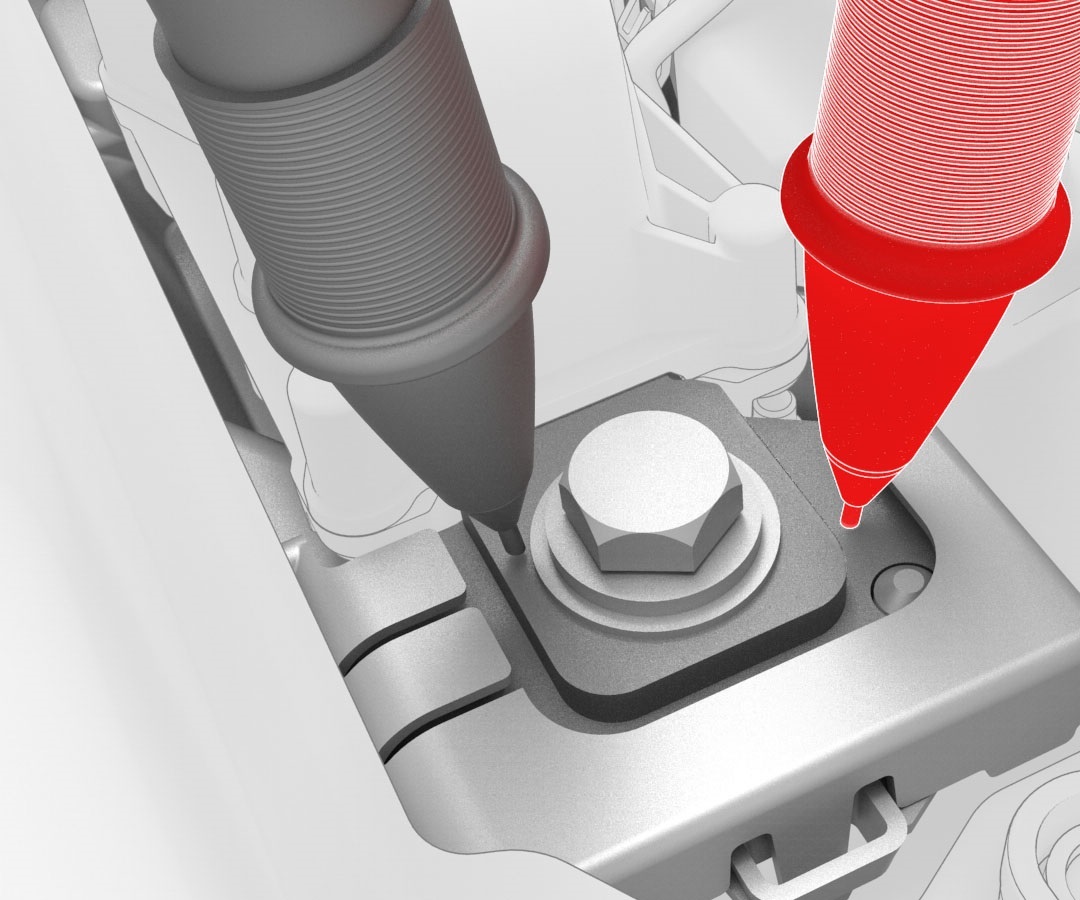 Generic Measurement - Actual busbars and fasteners might appear different
 -
Use the Hioki resistance meter to measure the resistance between the copper portion of the negative ring terminal and the busbar to which that terminal is secured.
Note: The maximum acceptable resistance is 0.150 mΩ (150 μΩ). If the resistance is above this value, escalate a Toolbox session, as appropriate.
Generic Measurement - Actual busbars and fasteners might appear different
-
Install the AC inlet terminal covers, and fasten the clips that attach the covers over the positive and negative ring terminals.
| 1 | Use an IPA wipe to clean the mating surfaces of the positive ring terminal to the positive busbar, and the negative ring terminal to the negative busbar. | ||
| 2 | Install the HV battery fast charge contactor cover onto the HV battery fast charge contactor, and fasten the clips (x8) that attach the cover to the contactor. | |
| 3 | Install new bolts to attach the positive and negative ring terminals to the busbars, and then mark the bolts with a paint pen after they are torqued. Torque 4.4 Nm | |
Generic Measurement - Actual busbars and fasteners might appear different
| 4 | Use the Hioki resistance meter to measure the resistance between the copper portion of the positive ring terminal and the busbar to which that terminal is secured. Note: The maximum acceptable resistance is 0.150 mΩ (150 μΩ). If the resistance is above this value, escalate a Toolbox session, as appropriate.
| |
Generic Measurement - Actual busbars and fasteners might appear different
| 5 | Use the Hioki resistance meter to measure the resistance between the copper portion of the negative ring terminal and the busbar to which that terminal is secured. Note: The maximum acceptable resistance is 0.150 mΩ (150 μΩ). If the resistance is above this value, escalate a Toolbox session, as appropriate.
| |
| 6 | Install the AC inlet terminal covers, and fasten the clips that attach the covers over the positive and negative ring terminals. | |
| 7 | Install the HV battery fast charge contactor. See Contactor - Fast Charge - HV Battery (Remove and Replace). |