Module - Body Controller - RH (Remove and Replace)
Correction code 1715220217152202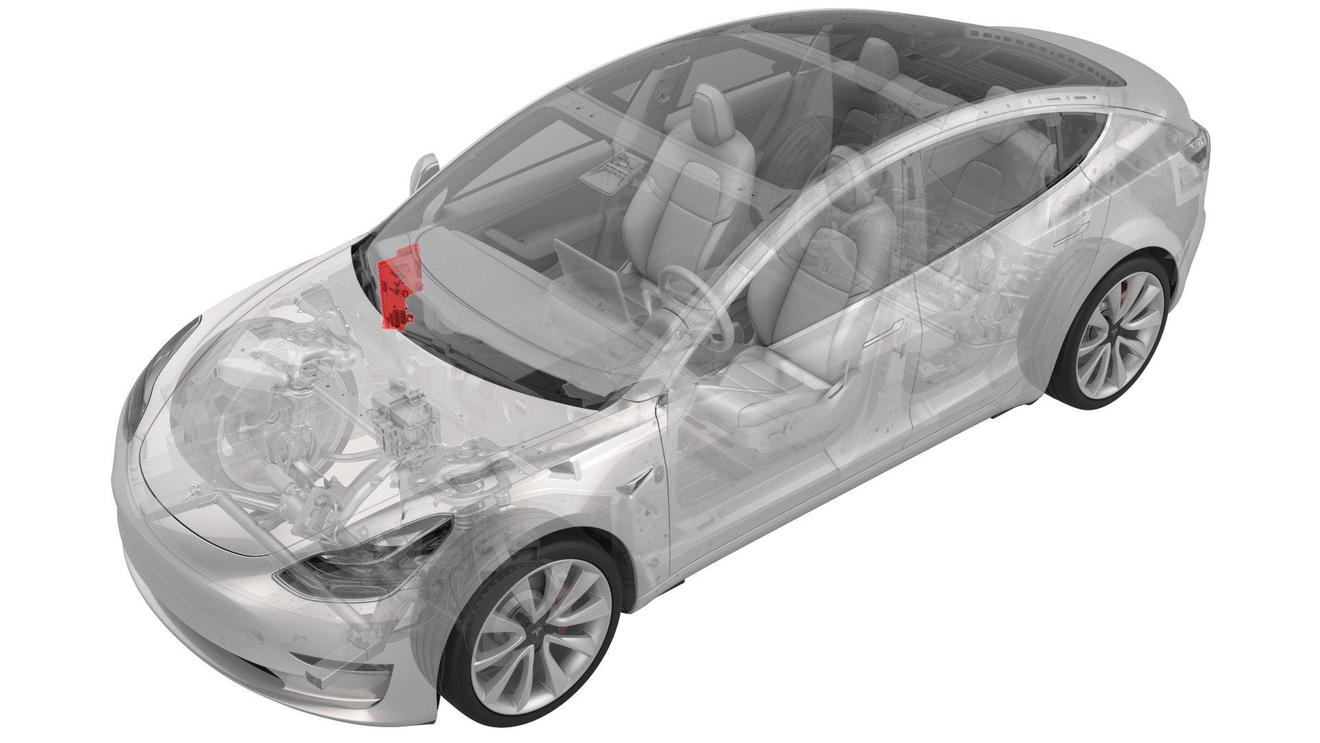
Remove
-
Remove the rear underhood apron. See Underhood Apron - Rear (Remove and Replace).
 Caution:Do not proceed until the climate control system has been powered off for at least 30 seconds. Do not disconnect 12V power while the climate control system is operational.
 -
Release the clips that attach the RH front carpet to the RH footwell.
-
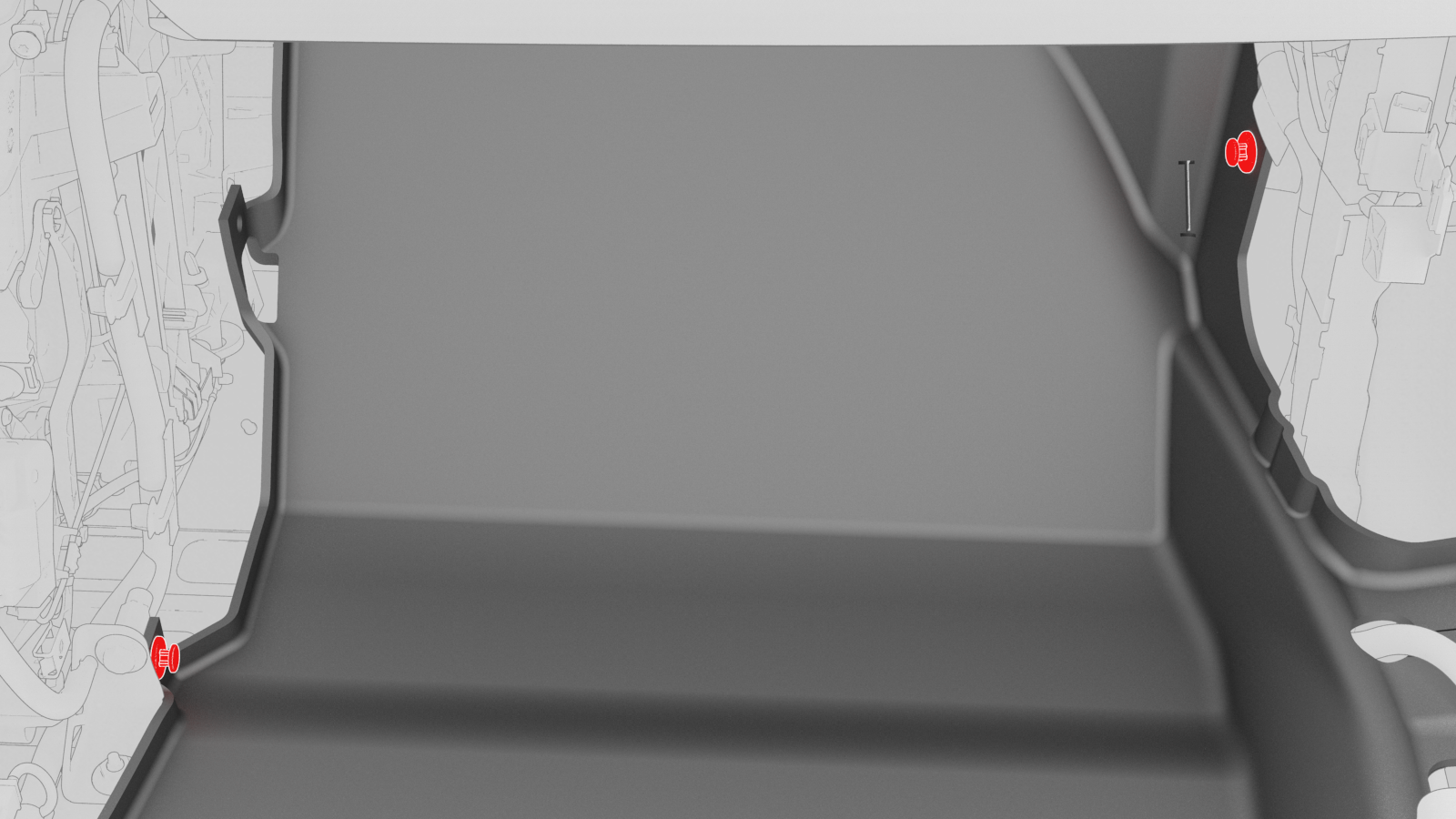
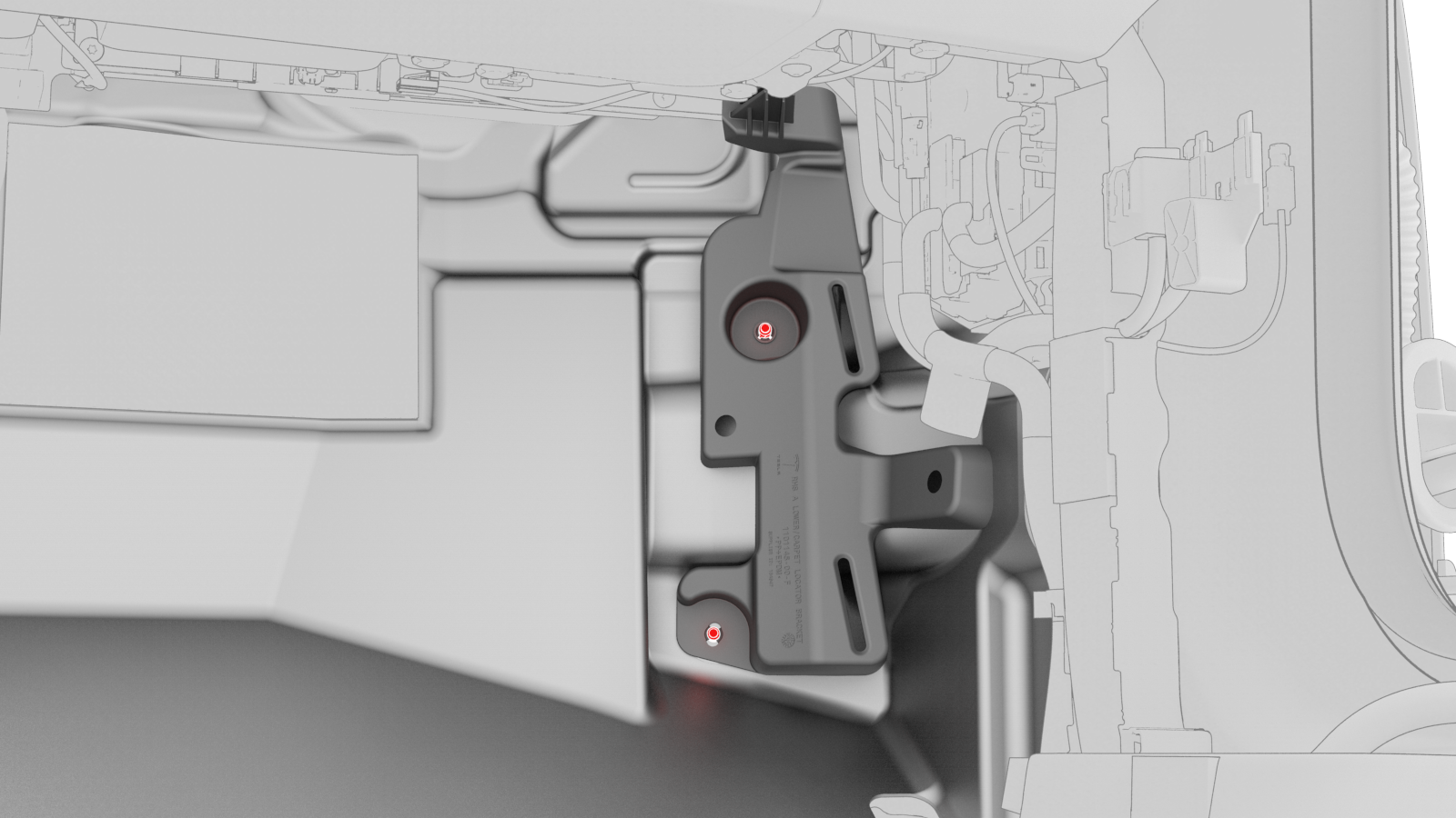
Remove the nuts that attach the RH side carpet locator bracket to the vehicle, and then remove the RH side carpet locator bracket from the vehicle.
-
Disconnect the electrical connectors from the RH body controller module.
-
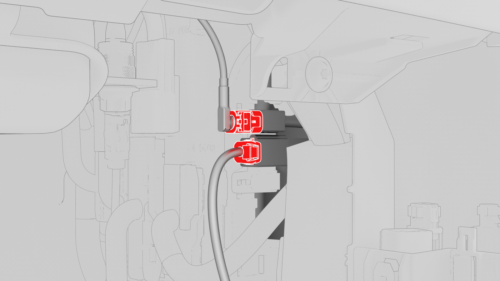
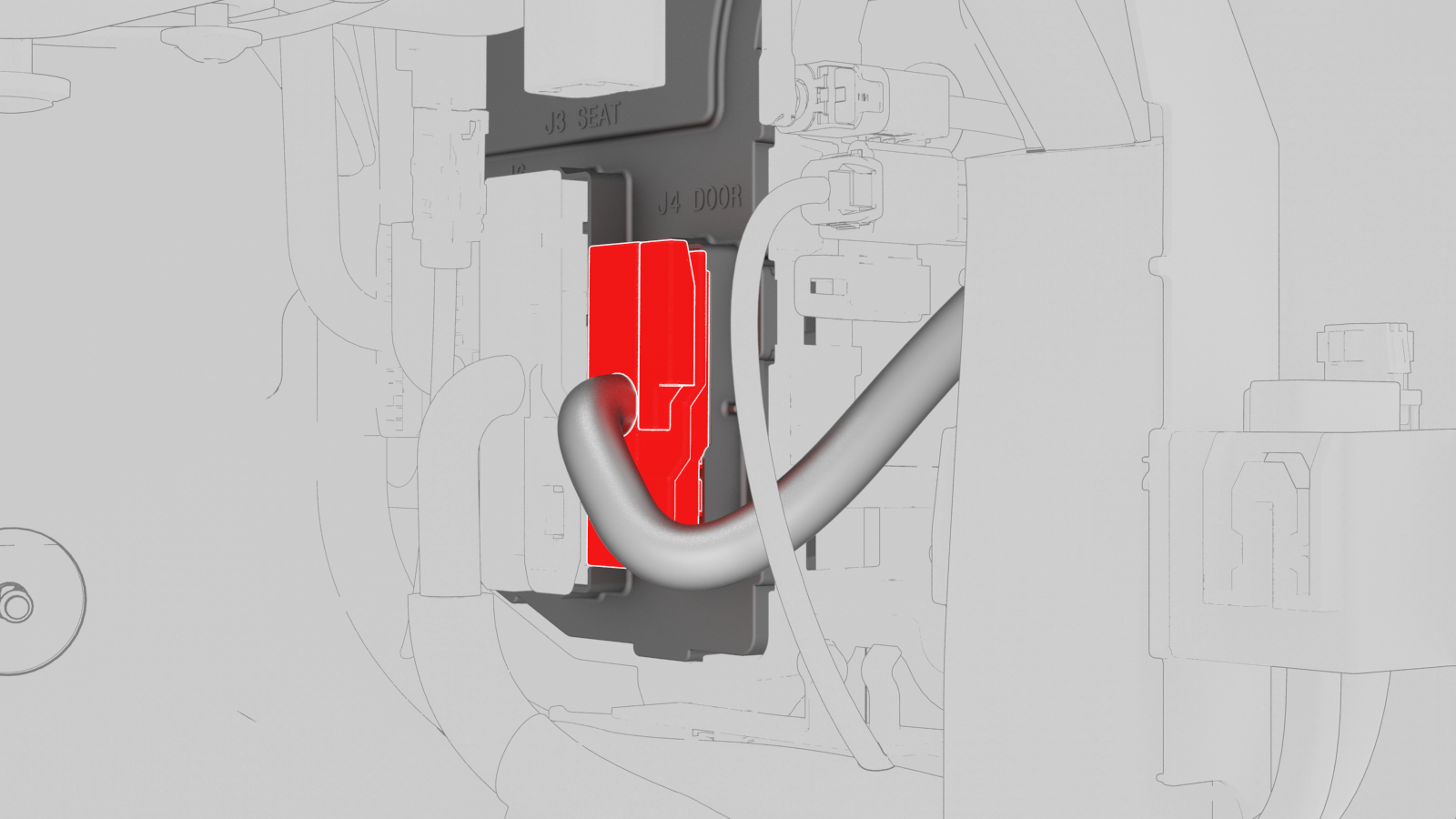
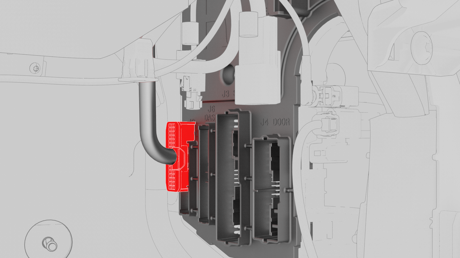
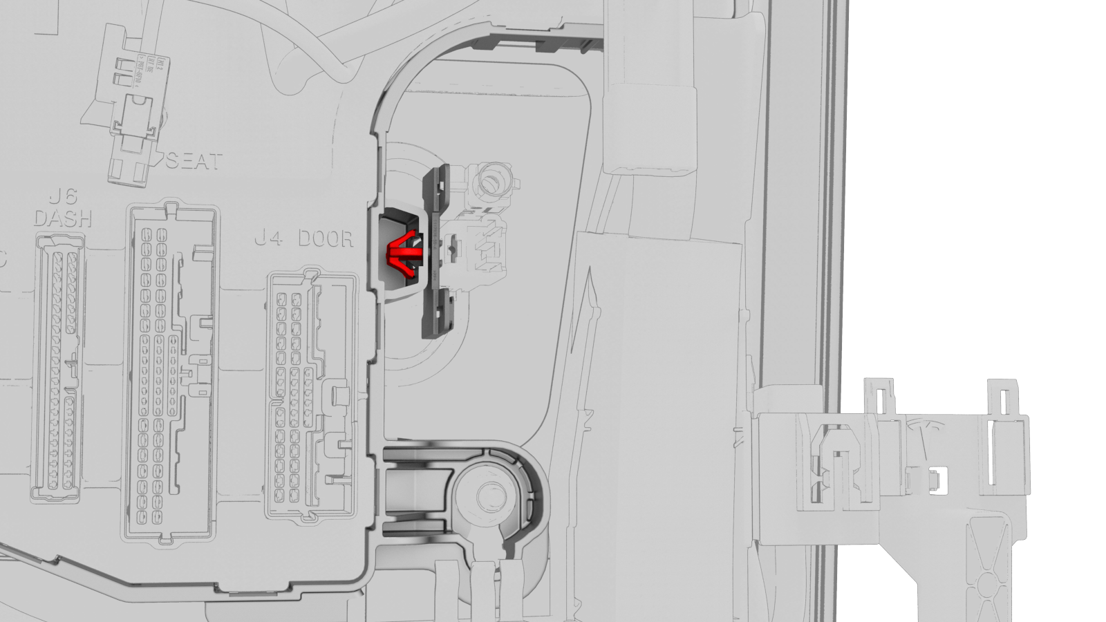
Release the lock, and then disconnect the RH front door electrical connector from the RH body controller module.
-
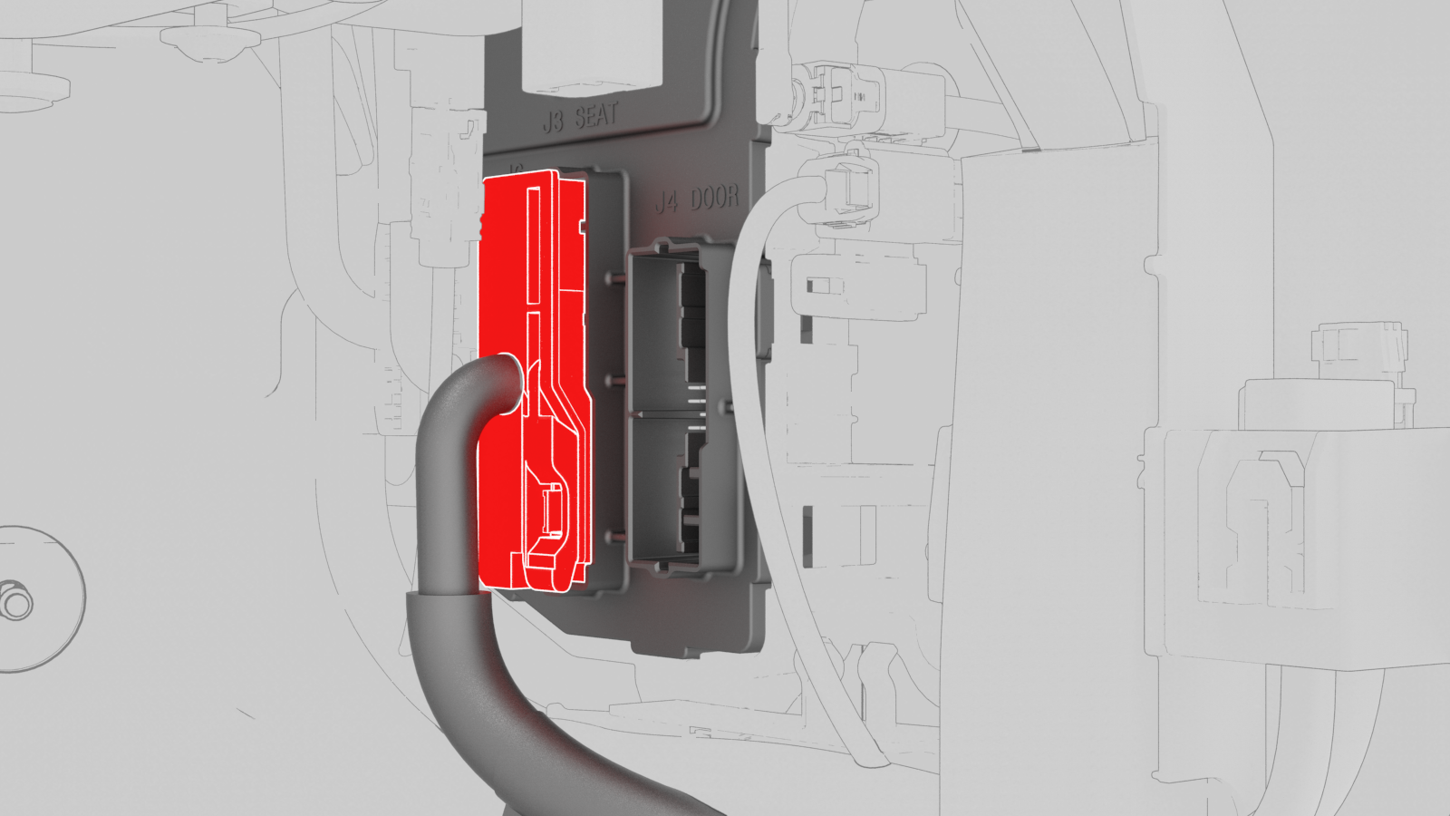
Release the lock, and then disconnect the front passenger seat electrical connector from the RH body controller module.
-
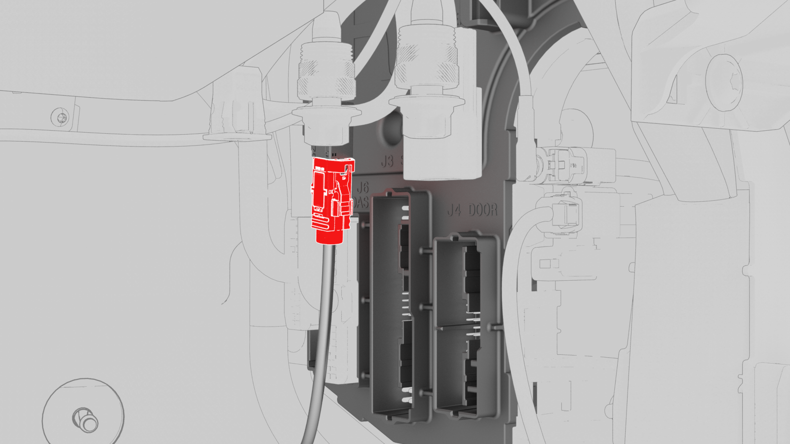
Disconnect the instrument panel harness coaxial cable from the RH body controller module.
-
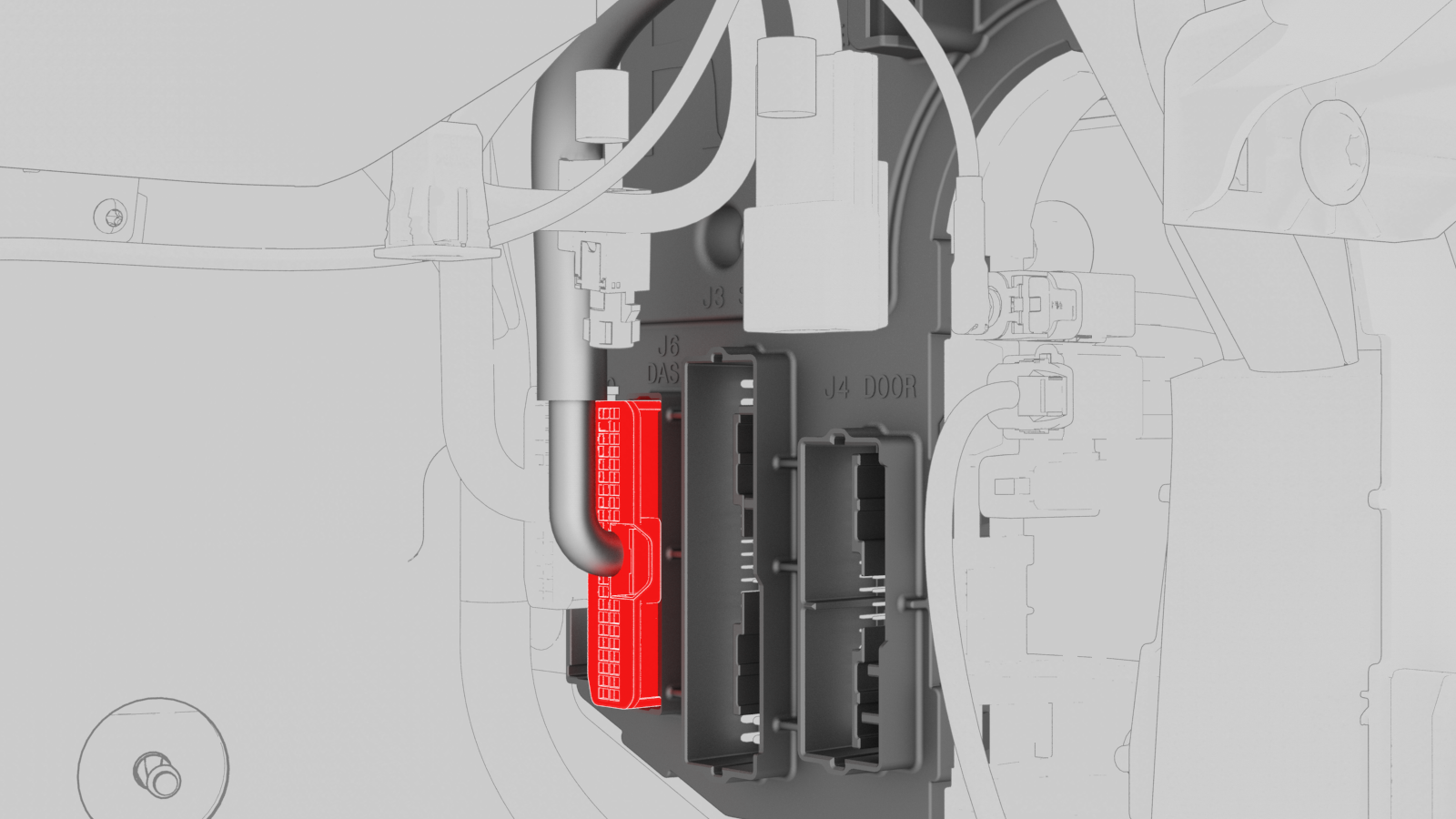
Disconnect the instrument panel electrical connector from the RH body controller module.
-
Disconnect the HVAC connector from the RH body controller module.
-
Disconnect the front harness connector from the RH body controller module.
-
Release the clip that attaches the inline electrical connector to the RH body controller module, and then disconnect the electrical connector.
-
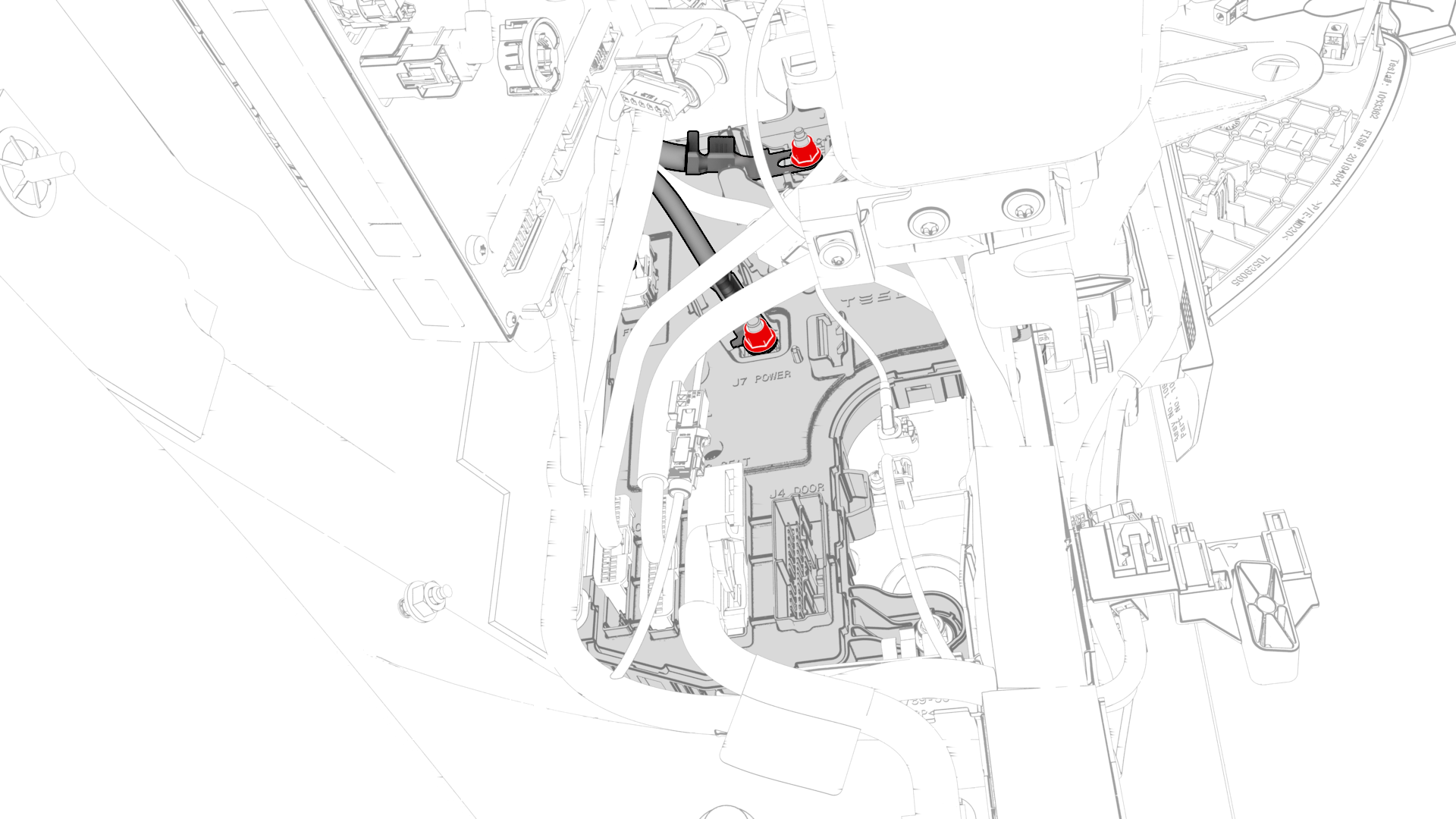
Remove and discard the nuts that attach the electrical wiring to the RH body controller module, and remove the electrical wiring from the RH body controller module.
-
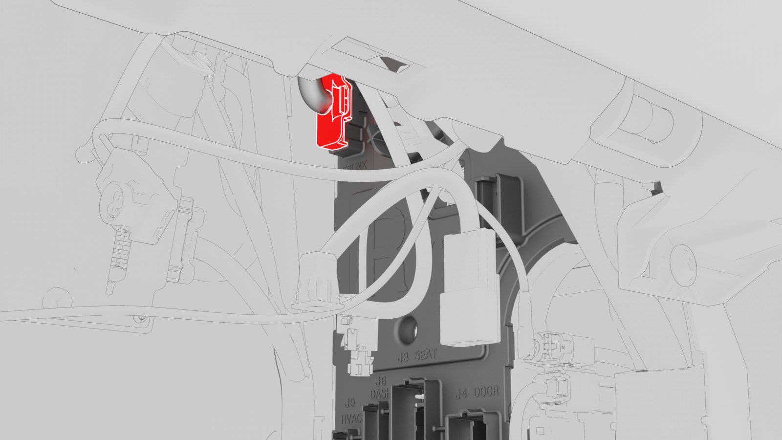
Release the lock, and then disconnect the body 1 electrical connector from the RH body controller module.
 Caution:To avoid damage, carefully remove the body 1 electrical connector because the lock may get hung up on the IP carrier.
 -
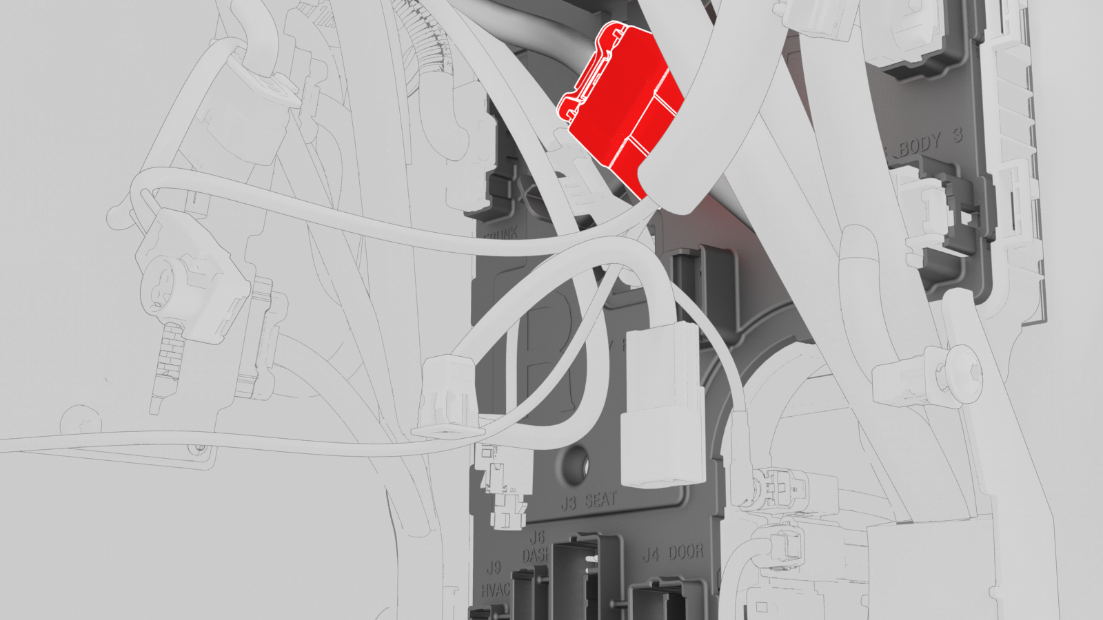
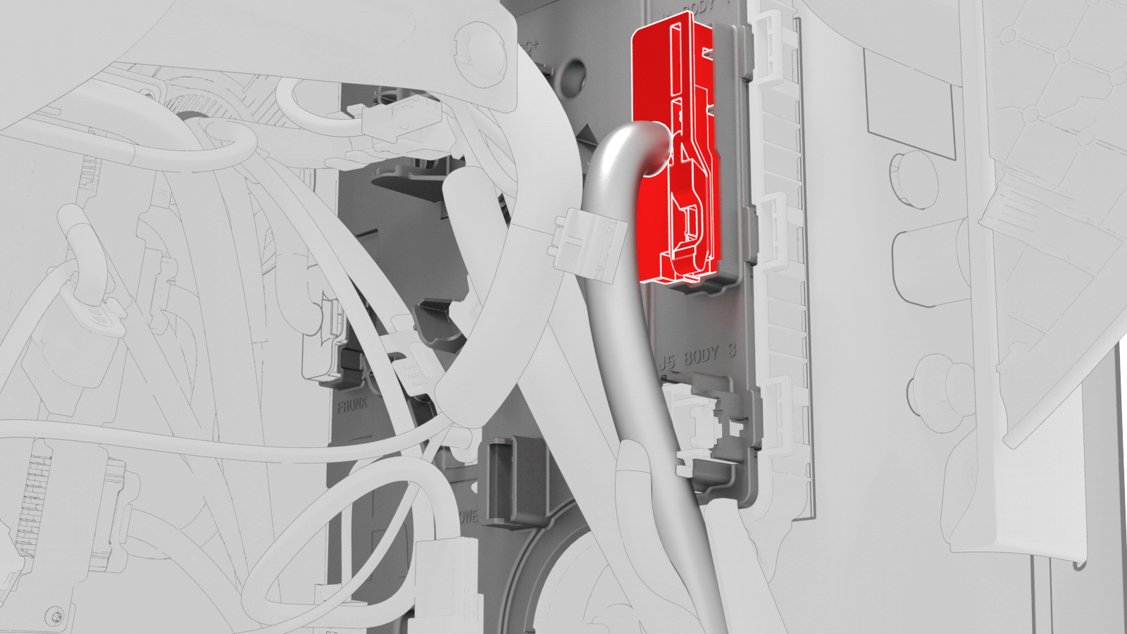
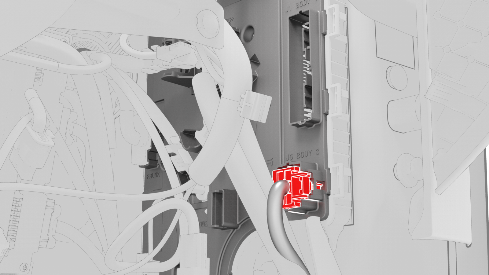
Release the lock, and then disconnect the body 3 electrical connector from the RH body controller module.
-
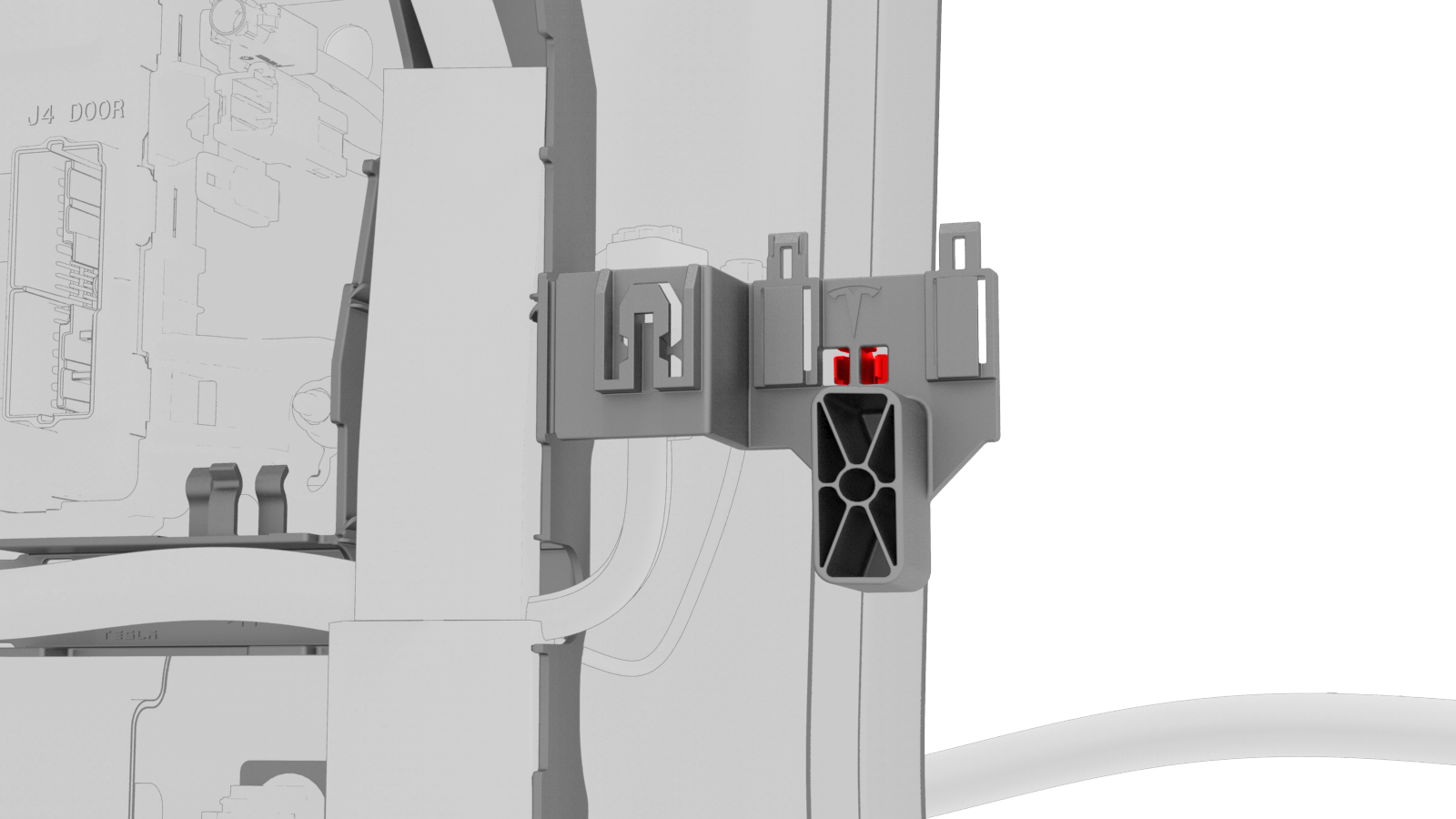
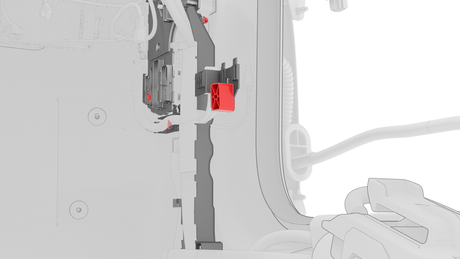
Release the clip that attaches the electrical harness to the RH lower A-pillar area.
-
Release the clips that attach the RH body electrical harness to the RH body controller module.
-
Release the clip that attaches the wiring harness to the RH body controller module.
-
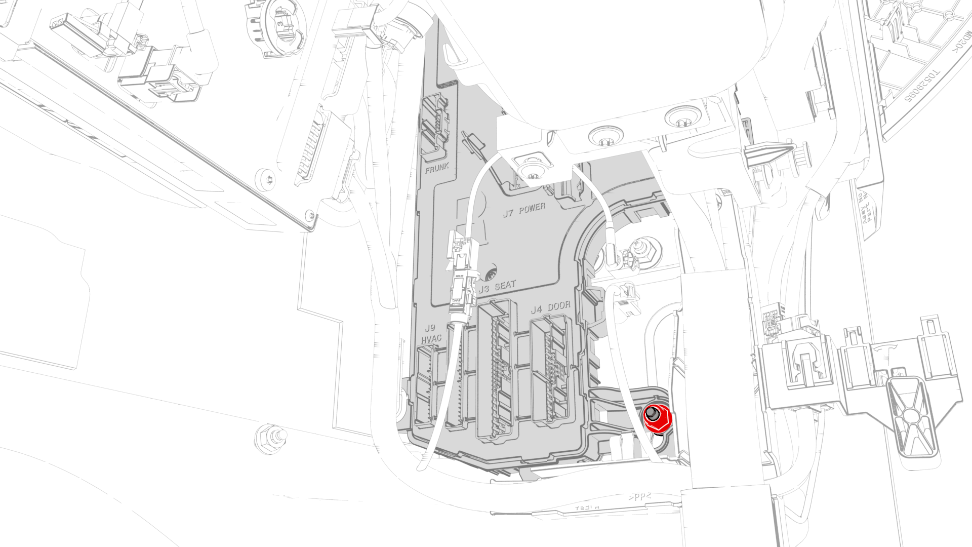
Remove and discard the nut that attaches the RH body controller module to the body.
-
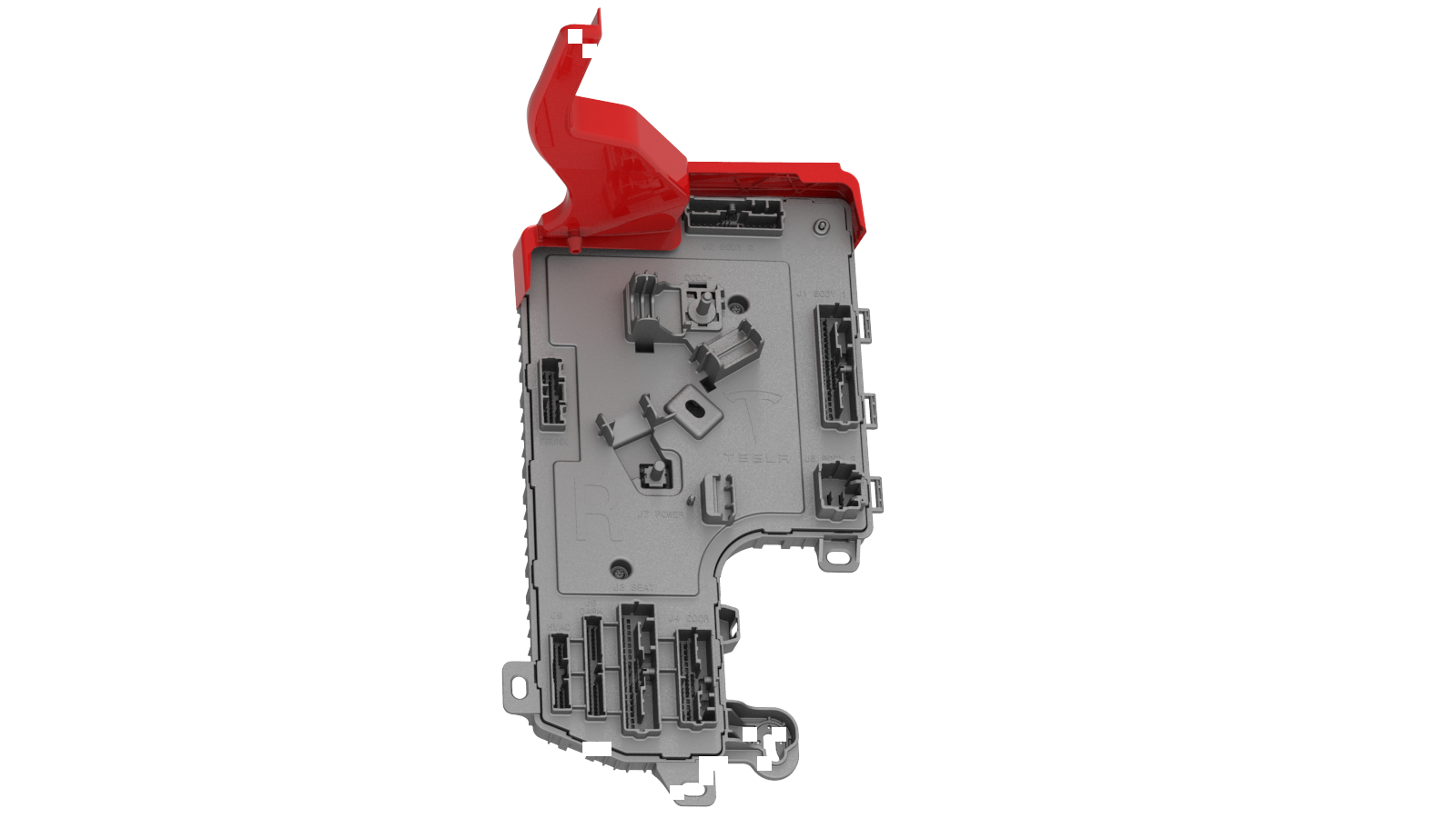
Slide the RH body controller upwards to release the W-clip, then move the RH body controller out from underneath the instrument panel, and then remove the RH body controller from the vehicle.
-
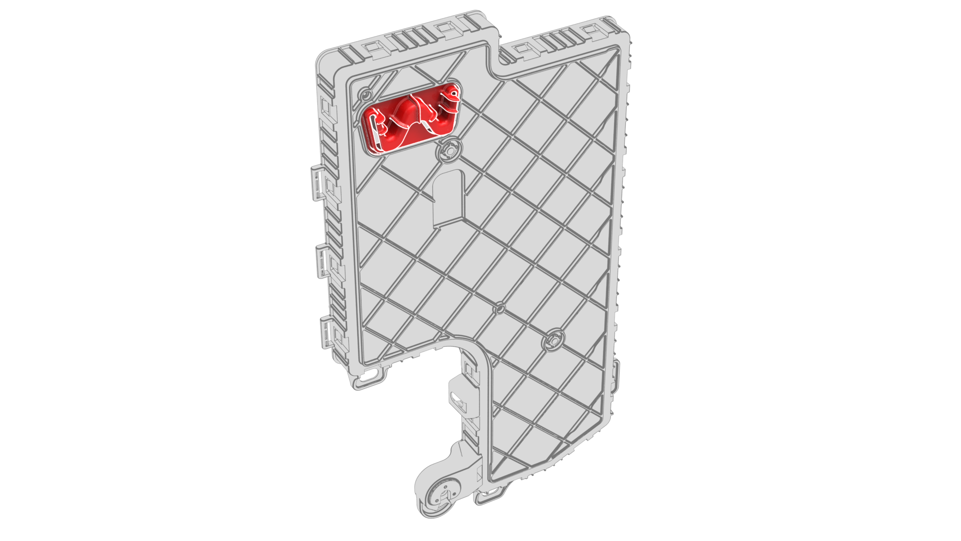
If the RH body controller module has a shroud installed, release the clips that attach the shroud to the module.
| 1 | On the touchscreen, power off the climate control system, and wait at least 30 seconds for the climate control system to completely shut down. | ||
| 2 | Remove the 2nd row lower seat cushion. See Seat Cushion - Lower - 2nd Row (Remove and Replace). | ||
| 3 | Remove the rear underhood apron. See Underhood Apron - Rear (Remove and Replace). Caution: Do not proceed until the climate control system has been powered off for at least 30 seconds. Do not disconnect 12V power while the climate control system is operational.
| ||
| 4 | Disconnect 12V power. See 12V Power (Disconnect and Connect). | ||
| 5 | Remove the LH instrument panel end cap. See End Cap - Instrument Panel - LH (Remove and Replace). | ||
| 6 | Remove the LH air wave end cap. See End Cap - Air Wave - LH (Remove and Replace). | ||
| 7 | Remove the RH instrument panel end cap. See End Cap - Instrument Panel - LH (Remove and Replace). | ||
| 8 | Remove the RH air wave end cap. See End Cap - Air Wave - LH (Remove and Replace). | ||
| 9 | Remove the main instrument panel decor trim. See Decor Trim - Instrument Panel - Main (Remove and Replace). | ||
| 10 | Remove the RH middle A-pillar trim. See Trim - A-Pillar - Middle - LH (Remove and Replace). | ||
| 11 | Remove the RH lower A-pillar trim. See Trim - A-Pillar - Lower - LH (Remove and Replace). | ||
| 12 | Remove the passenger footwell cover. See Cover - Footwell - Passenger (LHD) (Remove and Replace). | ||
| 13 | Remove the front passenger knee airbag. See Airbag - Knee - Front Passenger (Remove and Replace). | ||
| 14 | Remove the glove box. See Glove Box (LHD) (Remove and Replace). | ||
| 15 | Remove the RH front floor mat. | ||
| 16 | Remove the RH center console side panel carpet. See Carpet - Side Panel - Center Console - LH (Remove and Replace). | ||
| 17 | Release the clips that attach the RH front carpet to the RH footwell. | |
| 18 | Fold back the RH front carpet. | ||
| 19 | Remove the nuts that attach the RH side carpet locator bracket to the vehicle, and then remove the RH side carpet locator bracket from the vehicle. | |
| 20 | Disconnect the electrical connectors from the RH body controller module. | |
| 21 | Release the lock, and then disconnect the RH front door electrical connector from the RH body controller module. | |
| 22 | Release the lock, and then disconnect the front passenger seat electrical connector from the RH body controller module. | |
| 23 | Disconnect the instrument panel harness coaxial cable from the RH body controller module. | |
| 24 | Disconnect the instrument panel electrical connector from the RH body controller module. | |
| 25 | Disconnect the HVAC connector from the RH body controller module. | |
| 26 | Disconnect the front harness connector from the RH body controller module. | |
| 27 | Release the clip that attaches the inline electrical connector to the RH body controller module, and then disconnect the electrical connector. | |
| 28 | Remove and discard the nuts that attach the electrical wiring to the RH body controller module, and remove the electrical wiring from the RH body controller module. | |
| 29 | Release the electrical harness clips (x2) from underneath the IP carrier. | ||
| 30 | Release the lock, and then disconnect the body 2 electrical connector from the RH body controller module. | ||
| 31 | Release the lock, and then disconnect the body 1 electrical connector from the RH body controller module. Caution: To avoid damage, carefully remove the body 1 electrical connector because the lock may get hung up on the IP carrier.
| |
| 32 | Release the lock, and then disconnect the body 3 electrical connector from the RH body controller module. | |
| 33 | Disconnect the 3 inline electrical connectors at the RH lower A-pillar area. | ||
| 34 | Release the clip that attaches the electrical harness to the RH lower A-pillar area. | |
| 35 | Release the clips that attach the RH body electrical harness to the RH body controller module. | |
| 36 | Move the RH body harness away from the RH body controller module. | ||
| 37 | Release the clip that attaches the wiring harness to the RH body controller module. | |
| 38 | Remove and discard the nut that attaches the RH body controller module to the body. | |
| 39 | Slide the RH body controller upwards to release the W-clip, then move the RH body controller out from underneath the instrument panel, and then remove the RH body controller from the vehicle. | |
| 40 | If the RH body controller module has a shroud installed, release the clips that attach the shroud to the module. |
Install
-
Position the shroud by itself in position on the vehicle.
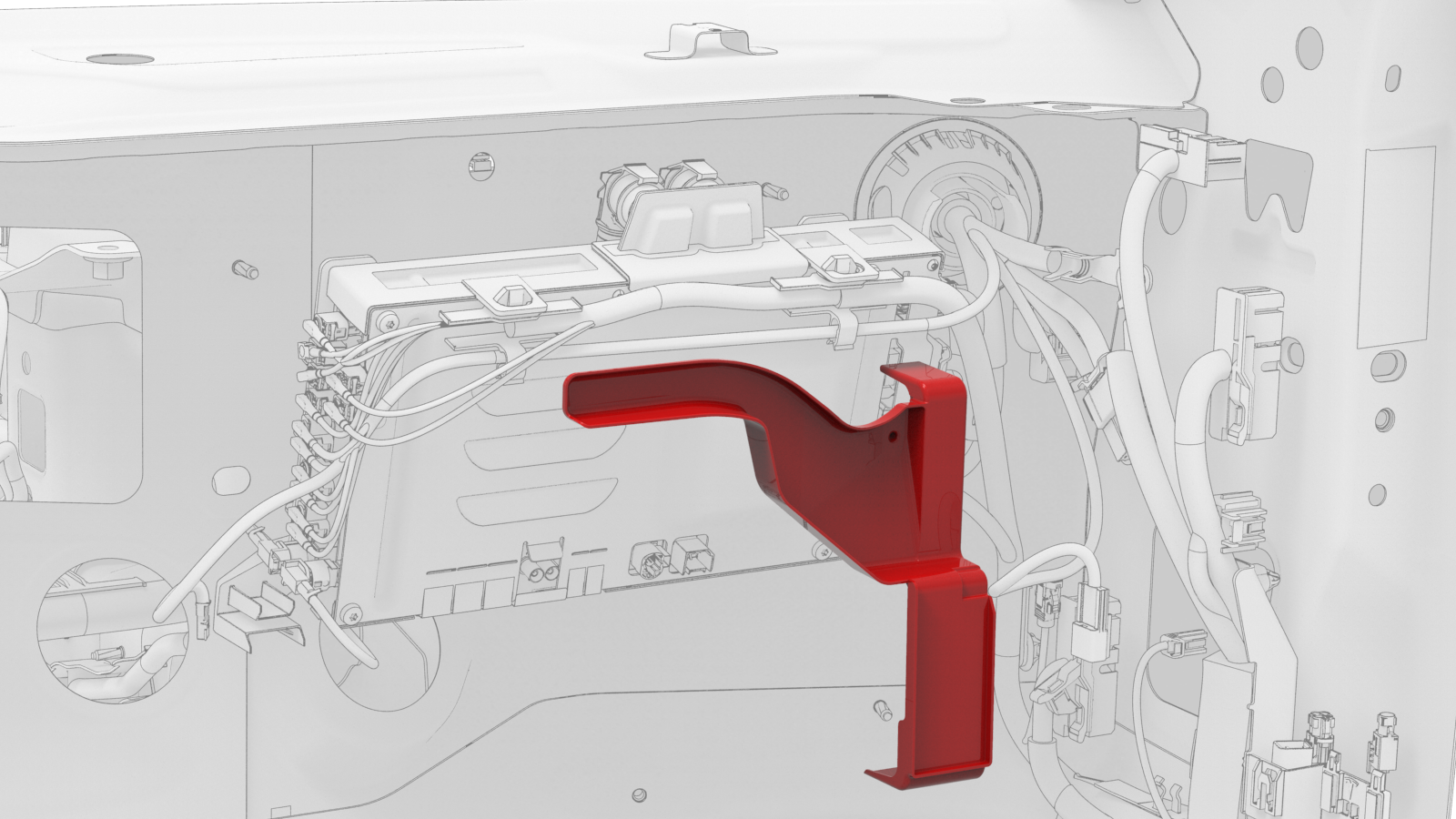 Note: Position the shroud vertical and move it up above the computer, and then pivot the lower edge so that the shroud sits horizontally.
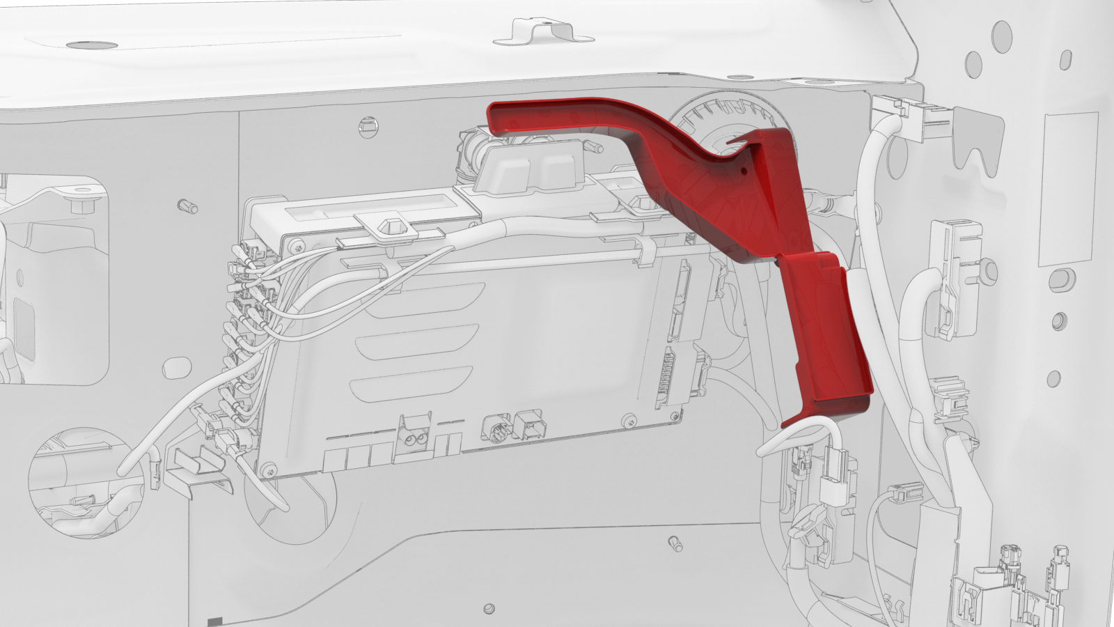
-
Maneuver the RH body controller module into position under the IP carrier, and then install the 2 clips that attach the shroud to the module.
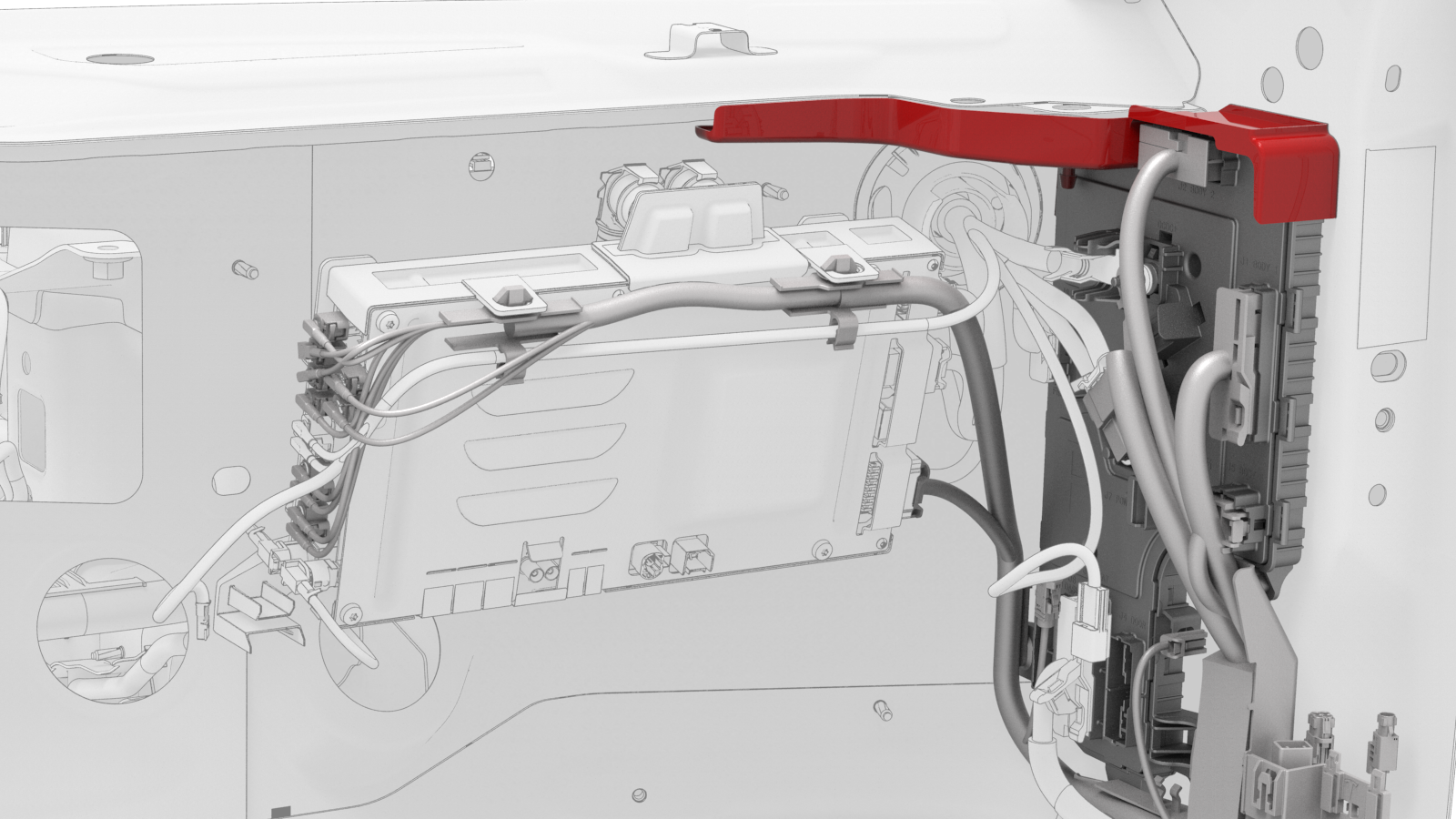 Note: Make sure that both clips are fully seated.
 -
Install new nut that attaches the RH body controller to the body.
-
Install the clip that attaches the wiring harness to the RH body controller.
-
Move the RH body harness towards the right side of the RH body controller, and then install attach the harness clips (x4) to the RH body controller.
-
Install the clip that attaches the RH body harness at the lower A-pillar area.
-
Connect the body 3 electrical connector onto the RH body controller module.
Note: Make sure that the body 3 electrical connector lock is fully engaged.
-
Connect the body 1 electrical connector onto the RH body controller module.
Note: Make sure that the body 1 electrical connector lock is fully engaged.
-
Install new nuts (x2) that attach the positive cables onto the RH body controller module.
-
Connect the inline electrical connector, and then attach it to the RH body controller module.
-
Connect the front wiring harness electrical connector onto the RH body controller module.
-
Connect the HVAC electrical connector onto the RH body controller module.
-
Connect the instrument panel electrical connector onto the RH body controller module.
-
Connect the instrument panel harness coaxial cable onto the RH body controller module.
-
Connect the front passenger seat electrical connector onto the RH body controller module.
Note: Make sure that the front passenger seat electrical connector lock is fully engaged.
-
Connect the RH front door electrical connector onto the RH body controller module.
Note: Make sure that the RH front door electrical connector lock is fully engaged.
-
Connect the RH front door wiring connectors onto the RH body controller module.
-
Install the nuts that attach the RH carpet locator bracket onto the vehicle.
 Torque 2.5 Nm
 -
Install the clips that attach the RH front carpet to the footwell area.
-
Connect 12V power. See 12V Power (Disconnect and Connect).
Caution:Do not power on the climate control system until the firmware has been updated, the seat and window calibration has been performed, and this procedure has been fully completed.
| 1 | Position the shroud by itself in position on the vehicle. Note: Position the shroud vertical and move it up above the computer, and then pivot the lower edge so that the shroud sits horizontally.
| |
| 2 | Maneuver the RH body controller module into position under the IP carrier, and then install the 2 clips that attach the shroud to the module. Note: Make sure that both clips are fully seated.
| |
| 3 | Align the W-clip with the body cutout, and then slide down to attach the RH body controller to the body. | ||
| 4 | Install new nut that attaches the RH body controller to the body. | |
| 5 | Install the clip that attaches the wiring harness to the RH body controller. | |
| 6 | Move the RH body harness towards the right side of the RH body controller, and then install attach the harness clips (x4) to the RH body controller. | |
| 7 | Install the clip that attaches the RH body harness at the lower A-pillar area. | |
| 8 | Connect the wiring harnesses at the RH lower A-pillar clip. | ||
| 9 | Connect the body 3 electrical connector onto the RH body controller module. Note: Make sure that the body 3 electrical connector lock is fully engaged.
| |
| 10 | Connect the body 1 electrical connector onto the RH body controller module. Note: Make sure that the body 1 electrical connector lock is fully engaged.
| |
| 11 | Connect the body 2 electrical connector onto the RH body controller module. Note: Make sure that the body 2 electrical connector lock is fully engaged.
| ||
| 12 | Install the harness clips (x2) onto the lower IP carrier. | ||
| 13 | Install new nuts (x2) that attach the positive cables onto the RH body controller module. | |
| 14 | Connect the inline electrical connector, and then attach it to the RH body controller module. | |
| 15 | Connect the front wiring harness electrical connector onto the RH body controller module. | |
| 16 | Connect the HVAC electrical connector onto the RH body controller module. | |
| 17 | Connect the instrument panel electrical connector onto the RH body controller module. | |
| 18 | Connect the instrument panel harness coaxial cable onto the RH body controller module. | |
| 19 | Connect the front passenger seat electrical connector onto the RH body controller module. Note: Make sure that the front passenger seat electrical connector lock is fully engaged.
| |
| 20 | Connect the RH front door electrical connector onto the RH body controller module. Note: Make sure that the RH front door electrical connector lock is fully engaged.
| |
| 21 | Connect the RH front door wiring connectors onto the RH body controller module. | |
| 22 | Install the nuts that attach the RH carpet locator bracket onto the vehicle. Torque 2.5 Nm | |
| 23 | Fold the RH front carpet back to its original position. | ||
| 24 | Install the clips that attach the RH front carpet to the footwell area. | |
| 25 | Install the RH center console side panel carpet. See Carpet - Side Panel - Center Console - LH (Remove and Replace). | ||
| 26 | Install the RH front floor mat. | ||
| 27 | Install the glove box. See Glove Box (LHD) (Remove and Replace). | ||
| 28 | Install the front passenger knee airbag. See Airbag - Knee - Front Passenger (Remove and Replace). | ||
| 29 | Install the passenger footwell cover. See Cover - Footwell - Passenger (LHD) (Remove and Replace). | ||
| 30 | Install the RH lower A-pillar trim. See Trim - A-Pillar - Lower - LH (Remove and Replace). | ||
| 31 | Install the RH middle A-pillar trim. See Trim - A-Pillar - Middle - LH (Remove and Replace). | ||
| 32 | Install the main instrument panel decor trim. See Decor Trim - Instrument Panel - Main (Remove and Replace). | ||
| 33 | Install the RH air wave end cap. See End Cap - Air Wave - LH (Remove and Replace). | ||
| 34 | Install the RH instrument panel end cap. See End Cap - Instrument Panel - LH (Remove and Replace). | ||
| 35 | Install the LH air wave end cap. See End Cap - Air Wave - LH (Remove and Replace). | ||
| 36 | Install the LH air wave end cap. See End Cap - Air Wave - LH (Remove and Replace). | ||
| 37 | Connect 12V power. See 12V Power (Disconnect and Connect). Caution: Do not power on the climate control system until the firmware has been updated, the seat and window calibration has been performed, and this procedure has been fully completed.
| ||
| 38 | Install the rear underhood apron. See Underhood Apron - Rear (Remove and Replace). | ||
| 39 | Install the 2nd row lower seat cushion. See Seat Cushion - Lower - 2nd Row (Remove and Replace). | ||
| 40 | Update the vehicle firmware. | ||
| 41 | Connect a laptop with Toolbox to the vehicle. | ||
| 42 | Using Toolbox, type Seat in the search field. Note: Make sure that Actions is selected in Toolbox, if not already.
| ||
| 43 | Using Toolbox, click the play button next to PROC_VCRIGHT_SEAT-CALIBRATE, and then select Run. | ||
| 44 | Using Toolbox, type Window in the search field. Note: Make sure that Actions is selected in Toolbox, if not already.
| ||
| 45 | Using Toolbox, click the play button next to PROC_VCLEFT-VCRIGHT_ X_WINDOW-CALIBRATION, and then select Run. | ||
| 46 | Disconnect the laptop from the vehicle. |