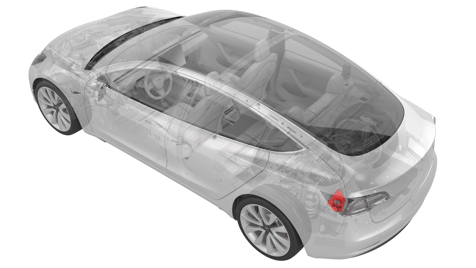
Carrier Assembly - Charge Port (Remove and Replace)
- 1076921-00-B Insulation Multimeter, Fluke 1507 (NA)
- 1076921-00-A Insulation Multimeter, Fluke 1587 (EMEA)
- 1076921-01-B Insulation Multimeter, Fluke 1508 (APAC)
- 1130480-00-A Test Probes, Slim, Fluke TP38
SPECIAL TOOLS
Insulation Multimeter, Fluke 1507 (NA) (1076921-00-B) |
Insulation Multimeter, Fluke 1587 (EMEA) (1076921-00-A) |
Insulation Multimeter, Fluke 1508 (APAC) (1076921-01-B) |
Test Probes, Slim, Fluke TP38 (1130480-00-A) |
 Warning:
Only technicians who have been trained in High Voltage Awareness are permitted to perform this procedure. Proper personal protective equipment (PPE) and insulating HV gloves with a minimum rating of class 0 (1000V) must be worn at all times a high voltage cable, busbar, or fitting is handled. Refer to Tech Note TN-15-92-003, "High Voltage Awareness Care Points" for additional safety information.
Warning:
Remove all jewelry (watches, bracelets, rings, necklaces, earrings, ID tags, piercings, etc.) from your person, and all objects (keys, coins, pens, pencils, tools, fasteners, etc.) from your pockets before performing any procedure that exposes you to high voltage.
Warning:
Proper personal protective equipment (PPE) is required to perform this procedure:
- High voltage insulating gloves
- Leather glove protectors
- High voltage glove tester
- Safety glasses
- Electrical hazard rated safety shoes
Warning:
A glove inflator is the only recommended way to test HV gloves. Both HV gloves must pass testing before beginning this procedure. If either glove does not pass the air check, discard the pair.
Warning:
Make sure that the HV gloves are not expired. HV gloves can be used up to 12 months after the testing date printed on the glove, but only 6 months after first use even if the gloves are still within the 12-month period.
Remove
-
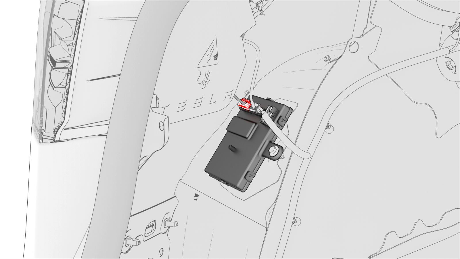
Disconnect the low voltage charge port connector from the charge port ECU.
-
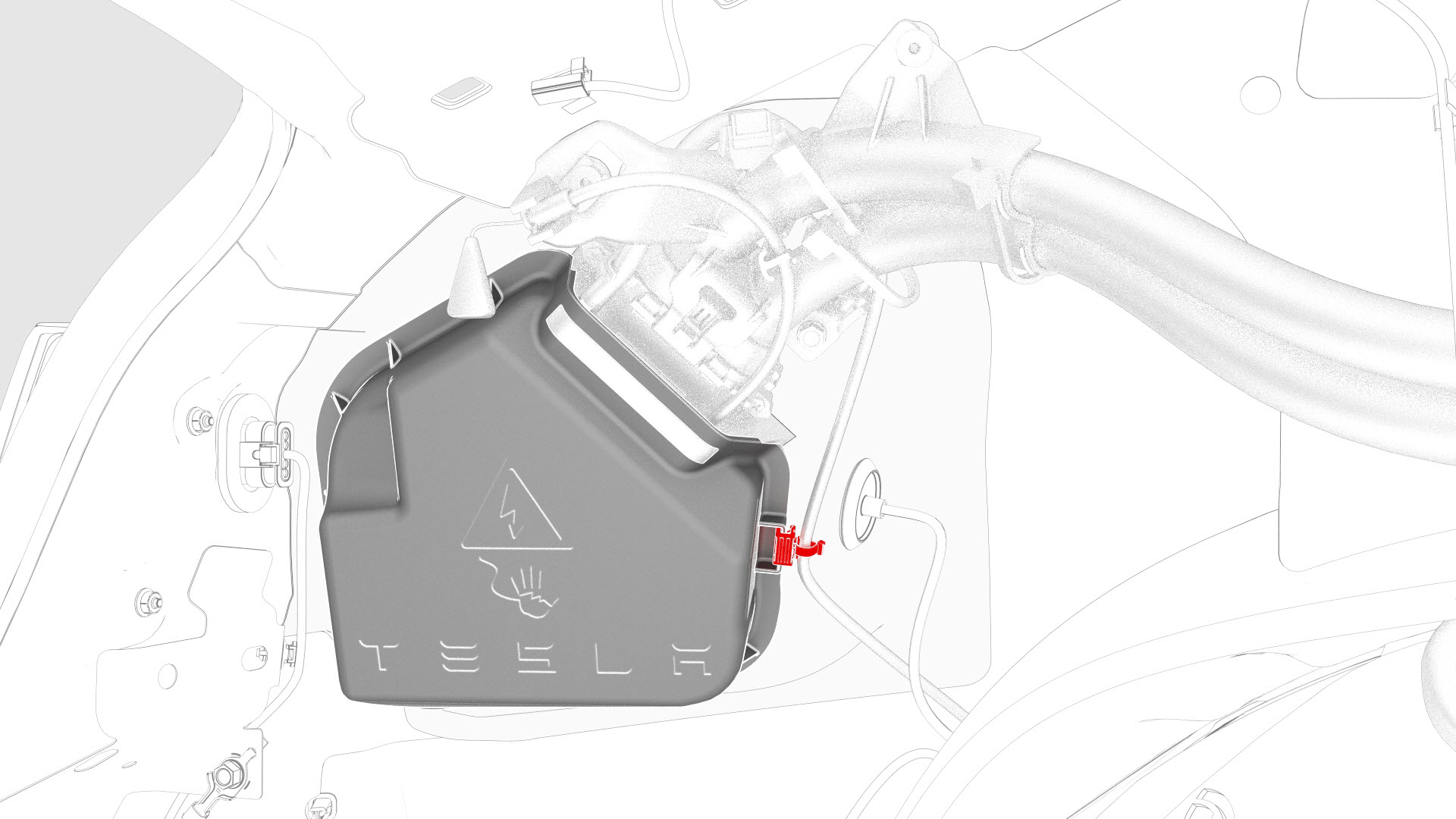
Release the clip that attaches the low voltage electrical wiring harness to the charge port closeout panel.
-
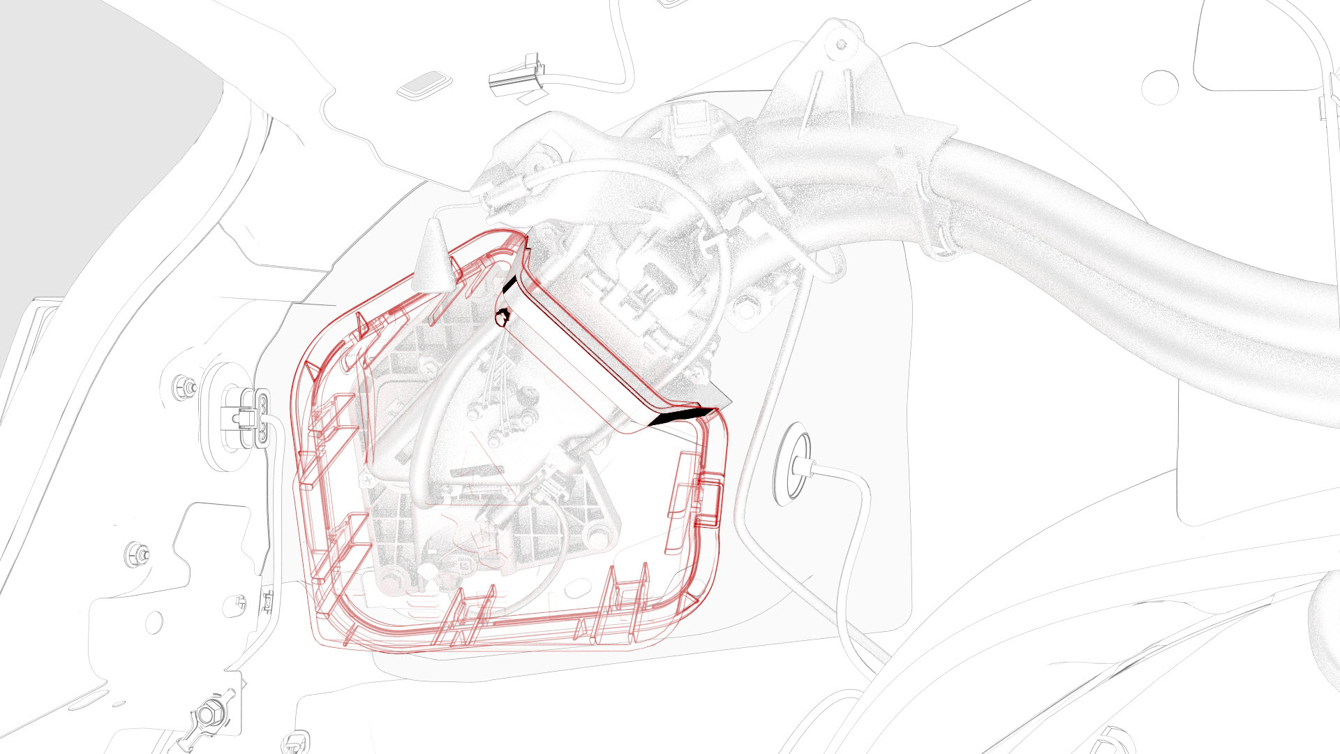
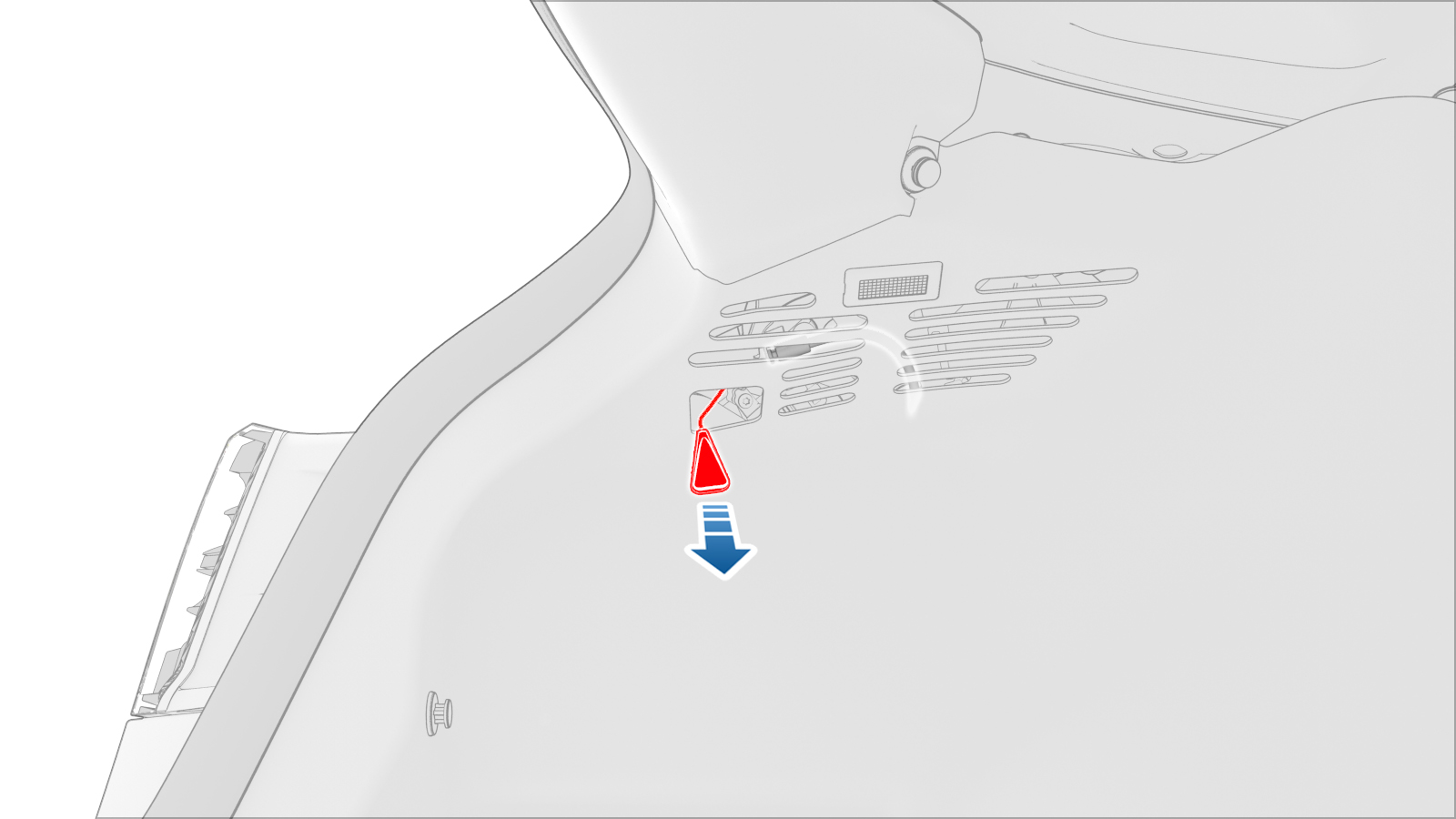
Release the tabs around the charge port closeout panel, and then remove the panel from the vehicle.
-
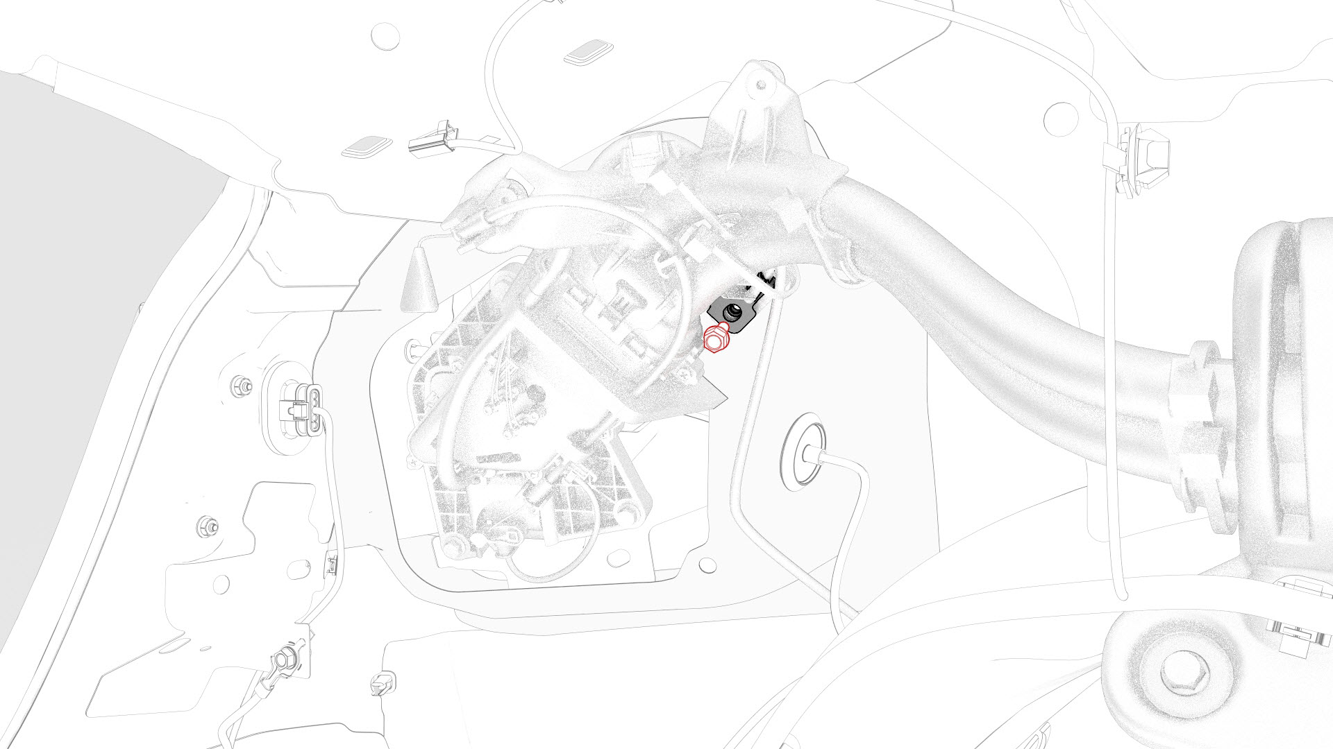
Remove the bolt that attaches the charge port electrical ground to the body.
-
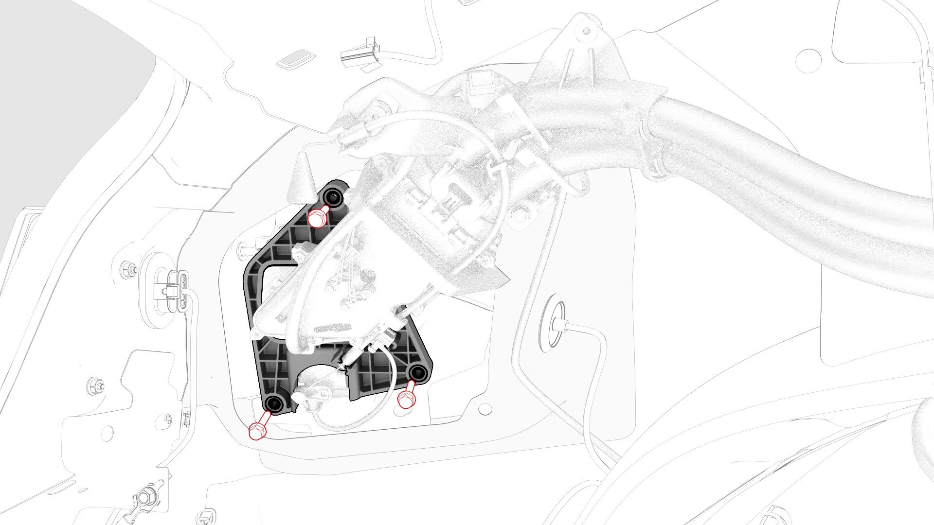
Remove the bolts that attach the charge port assembly to the body.
-
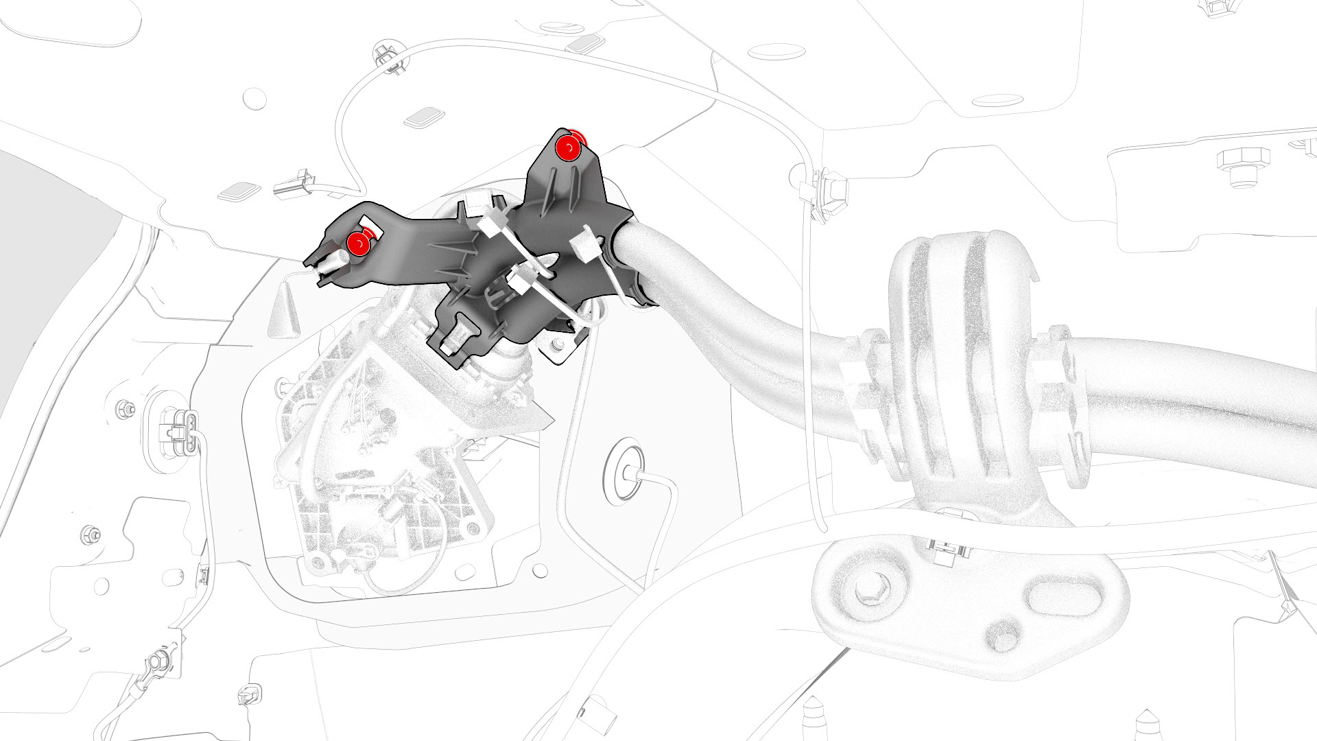
Release the clips that attach the charge port electrical harness to the body.
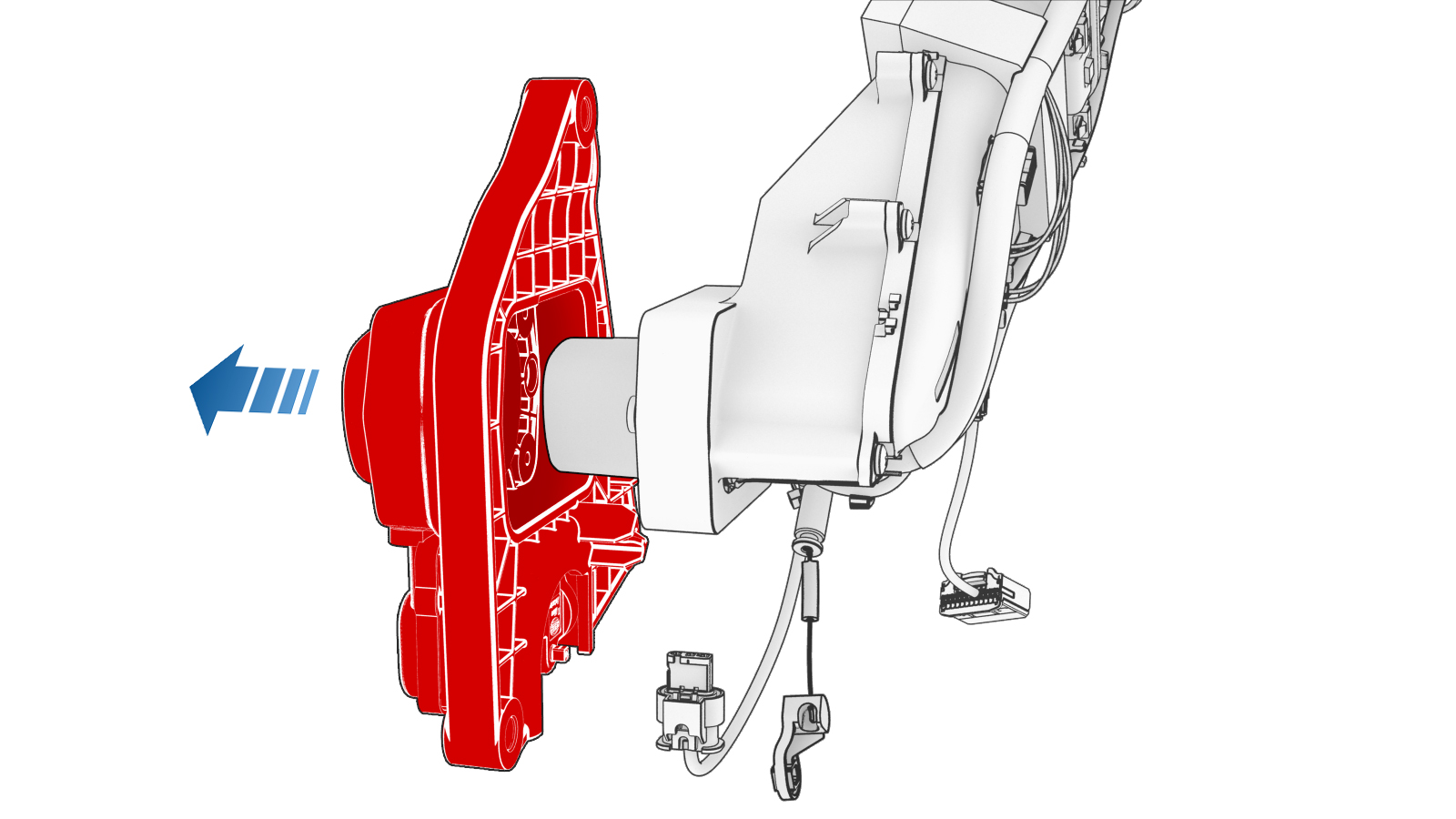
Note: Pull the charge port away from the body for access.
-
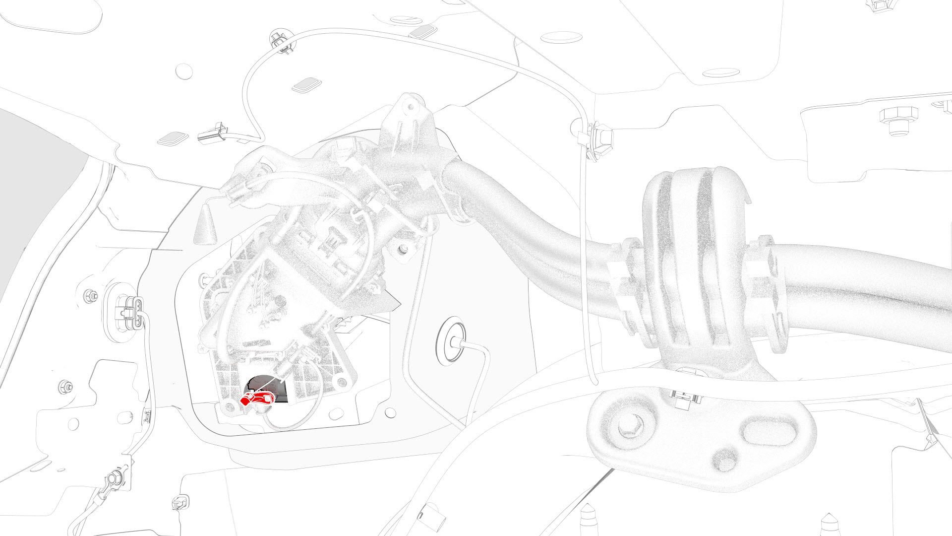
Remove the release arm from the latch actuator.
Note: Note the orientation of the release arm before removing it from the latch actuator.
-
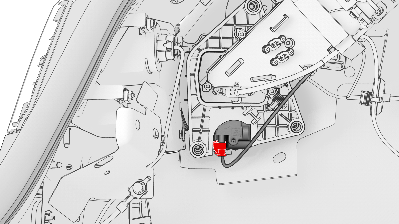
Release the latch cable from the locking tabs on the charge port assembly.
-
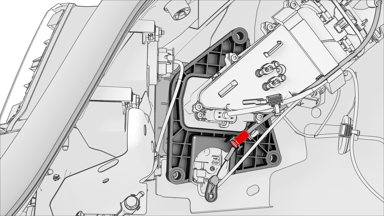
Disconnect the electrical connector from the latch actuator.
-
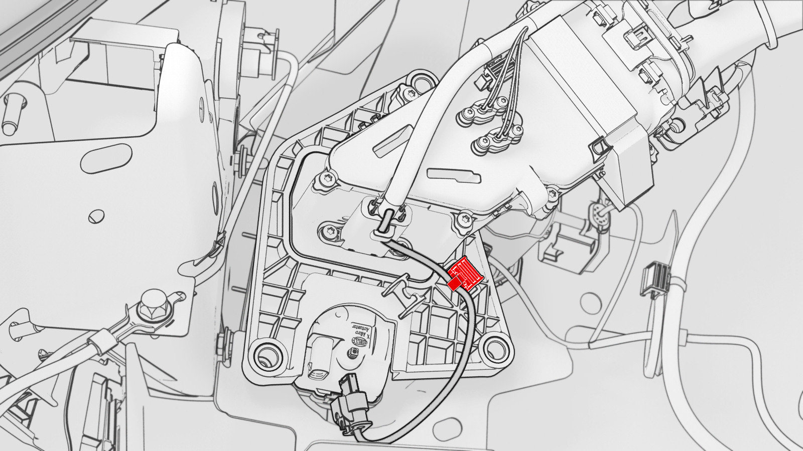
Release the clip that attaches the actuator harness to the charge port assembly, and then carefully cut the clip off of the harness.
Note: Note the location of the clip before cutting it off.
-
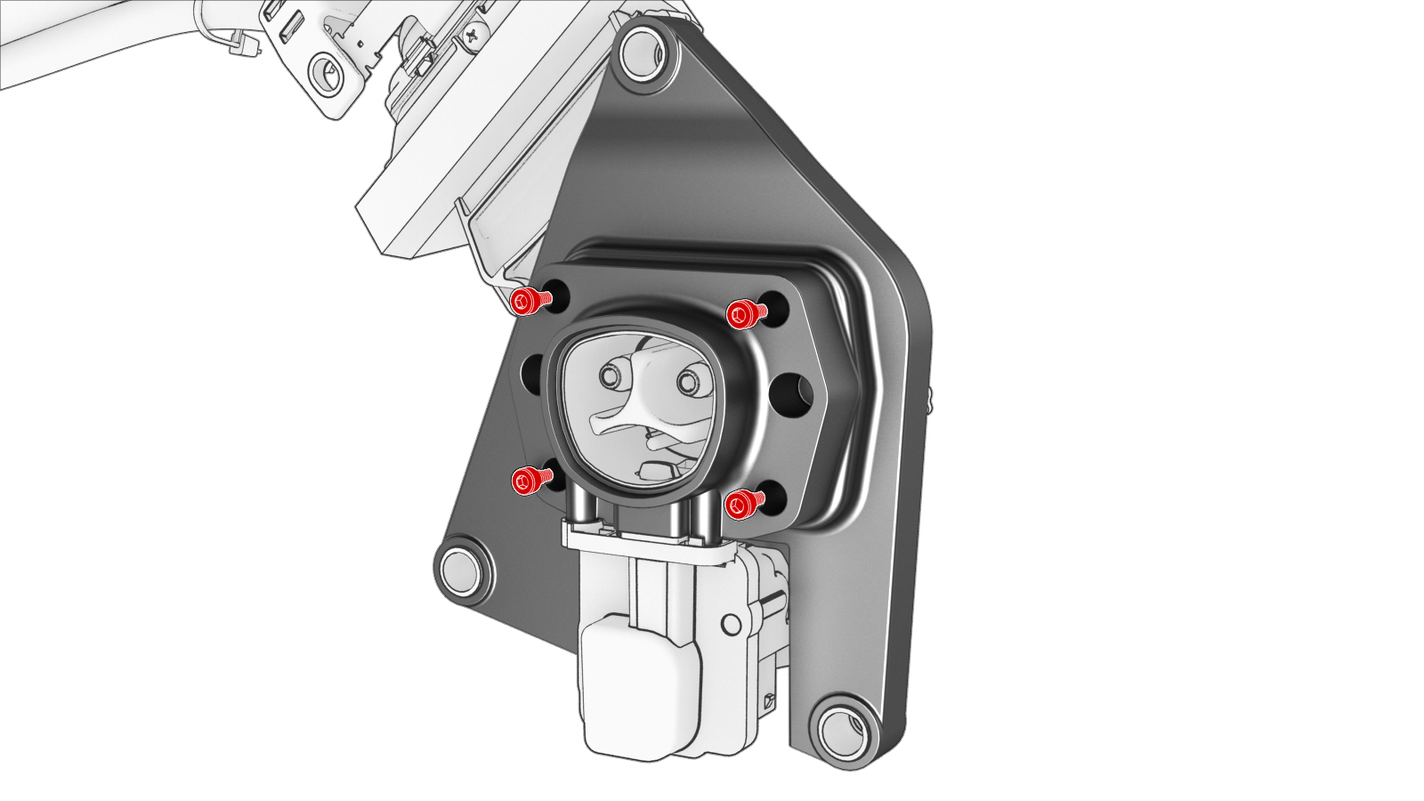
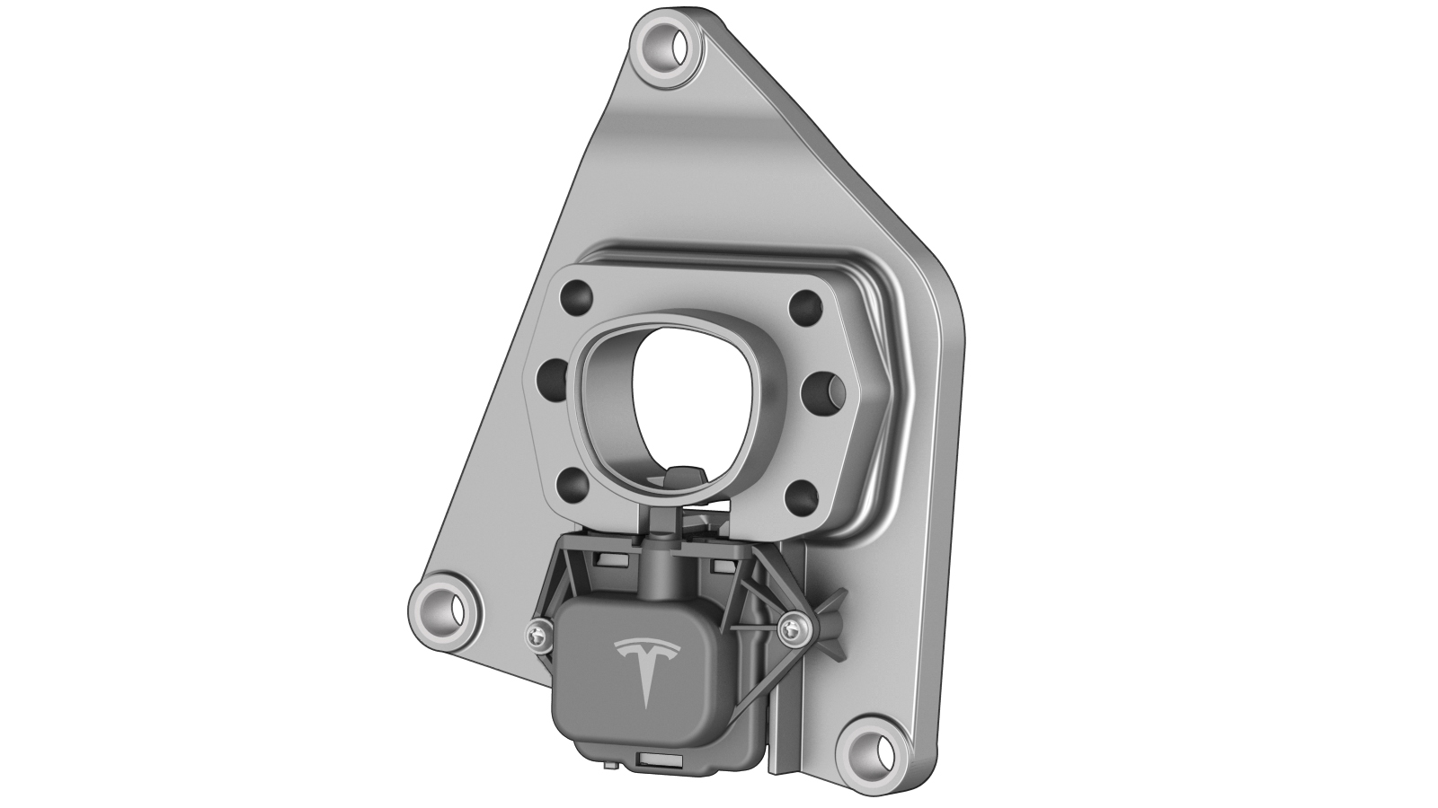
Remove the bolts that attach the carrier assembly to the charge port assembly, and then remove the carrier assembly.
Note: The carrier and latch actuator are removed together.
| 1 | Perform the charge port voltage check procedure. See Charge Port Voltage Check. | ||
| 2 | Remove the LH rear sill panel trim. See Trim - Sill Panel - Rear - LH (Remove and Replace). | ||
| 3 | Remove the LH trunk side trim. See Trim - Side - Trunk - LH (Remove and Replace). | ||
| 4 | Disconnect the low voltage charge port connector from the charge port ECU. | |
| 5 | Release the clip that attaches the low voltage electrical wiring harness to the charge port closeout panel. | |
| 6 | Release the tabs around the charge port closeout panel, and then remove the panel from the vehicle. | |
| 7 | Remove the bolt that attaches the charge port electrical ground to the body. | |
| 8 | Remove the bolts that attach the charge port assembly to the body. | |
| 9 | Release the clips that attach the charge port electrical harness to the body. Note: Pull the charge port away from the body for access.
| |
| 10 | Remove the release arm from the latch actuator. Note: Note the orientation of the release arm before removing it from the latch actuator.
| |
| 11 | Release the latch cable from the locking tabs on the charge port assembly. | |
| 12 | Disconnect the electrical connector from the latch actuator. | |
| 13 | Release the clip that attaches the actuator harness to the charge port assembly, and then carefully cut the clip off of the harness. Note: Note the location of the clip before cutting it off.
| |
| 14 | Remove the bolts that attach the carrier assembly to the charge port assembly, and then remove the carrier assembly. Note: The carrier and latch actuator are removed together.
|
Install
-
Position the new carrier assembly on the charge port assembly, and then install the bolts that attach the carrier assembly to the charge port assembly.
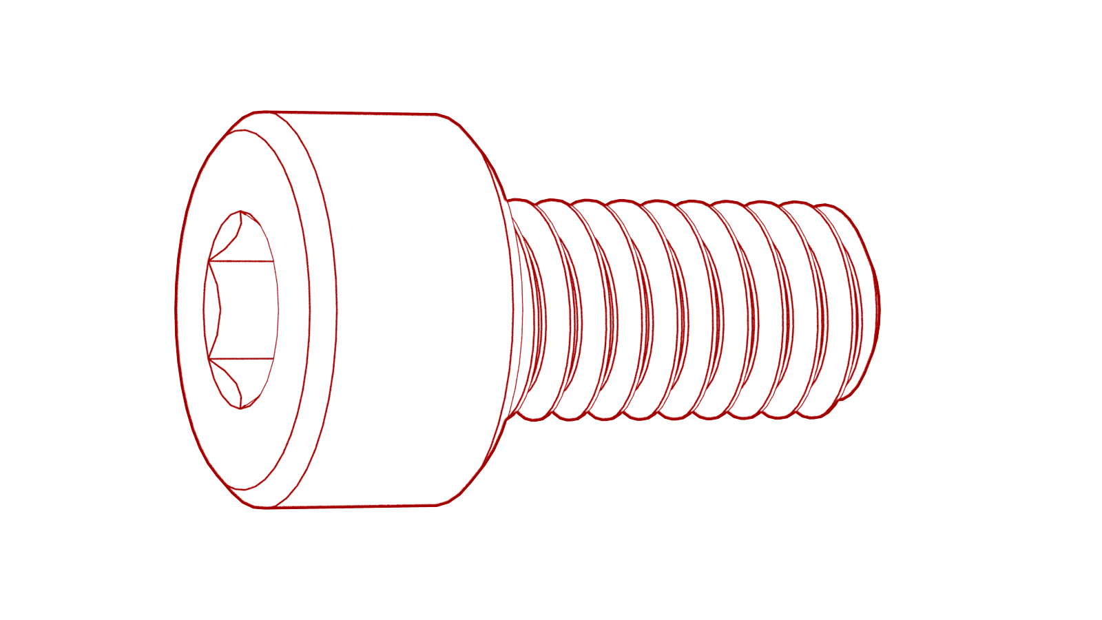 Torque 2.3 Nm
 -
Connect the electrical connector to the latch actuator.
-
Position the actuator harness on the carrier assembly as pictured, and then tighten the cable tie around the harness at the same location as the old clip.
-
Install the latch cable to the locking tabs on the carrier assembly.
-
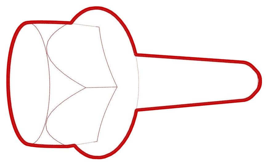
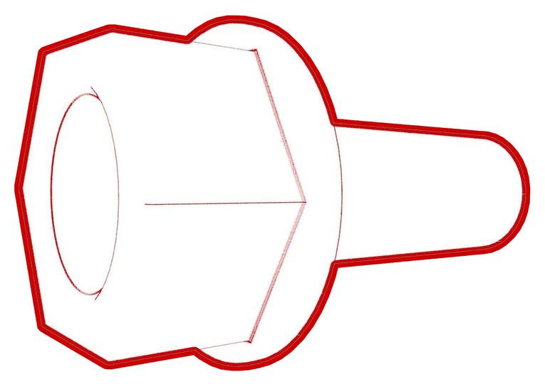
Install the release arm onto the latch actuator in the same position as when it was removed.
Note: After installation, manually rotate the release arm and check that the latch actuator moves.
 Caution:Ensure the latch actuator is oriented correctly, as shown below. Incorrect installation can result in inability to properly latch.
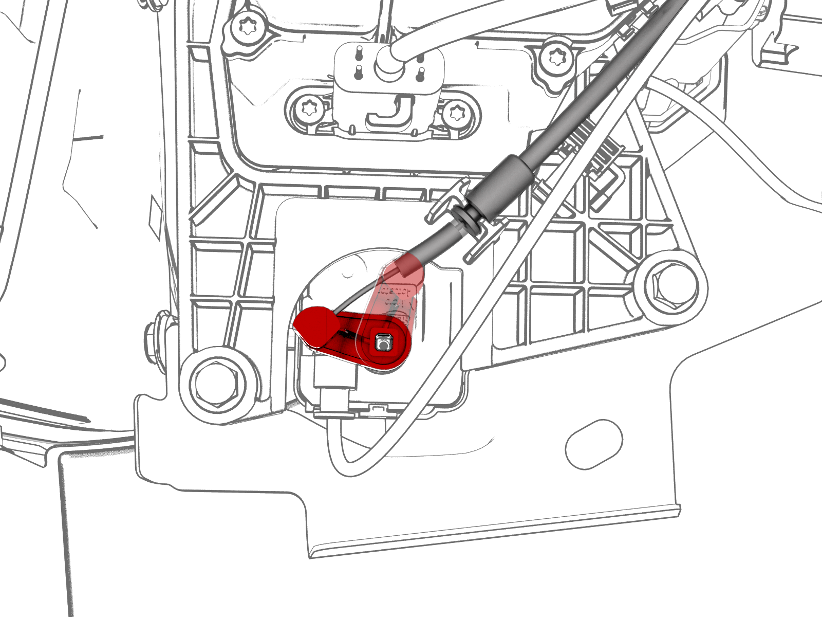
-
Install the clips that attach the charge port electrical harness to the body.
-
Install the bolts that attach the charge port assembly to the body.
 Torque 6 Nm
 -
Install the bolt that attaches the charge port electrical ground to the body.
 Torque 6 Nm
 -
Align the tabs around the charge port closeout panel, and then install the panel on the vehicle
-
Install the clip that attaches the low voltage electrical harness to the charge port closeout panel.
-
Connect the low voltage charge port connector to the charge port ECU.
-
Open the charge port door, and then plug an unpowered mobile connector into the charge port.
Caution:Do not plug any powered charge cable into the charge port at this time.
-
Verify latch functionality by pulling on the charge cable manual release while simultaneously pulling the mobile connector out of the charge port.
 Charge cable manual release
| 1 | Position the new carrier assembly on the charge port assembly, and then install the bolts that attach the carrier assembly to the charge port assembly. Torque 2.3 Nm | |
| 2 | Connect the electrical connector to the latch actuator. | |
| 3 | Position the actuator harness on the carrier assembly as pictured, and then tighten the cable tie around the harness at the same location as the old clip. | |
| 4 | Install the latch cable to the locking tabs on the carrier assembly. | |
| 5 | Install the release arm onto the latch actuator in the same position as when it was removed. Note: After installation, manually rotate the release arm and check that the latch actuator moves.
Caution: Ensure the latch actuator is oriented correctly, as shown below. Incorrect installation can result in inability to properly latch.
| |
| 6 | Position the charge port assembly on the body. | ||
| 7 | Install the clips that attach the charge port electrical harness to the body. | |
| 8 | Install the bolts that attach the charge port assembly to the body. Torque 6 Nm | |
| 9 | Install the bolt that attaches the charge port electrical ground to the body. Torque 6 Nm | |
| 10 | Align the tabs around the charge port closeout panel, and then install the panel on the vehicle | |
| 11 | Install the clip that attaches the low voltage electrical harness to the charge port closeout panel. | |
| 12 | Connect the low voltage charge port connector to the charge port ECU. | |
| 13 | Install the LH trunk side trim. See Trim - Side - Trunk - LH (Remove and Replace). | ||
| 14 | Install the LH rear sill panel trim. See Trim - Sill Panel - Rear - LH (Remove and Replace). | ||
| 15 | Reconnect 12V power. See 12V Power (Disconnect and Connect). | ||
| 16 | Install the 2nd row lower seat cushion. See Seat Cushion - Lower - 2nd Row (Remove and Replace). | ||
| 17 | Open the charge port door, and then plug an unpowered mobile connector into the charge port. Caution: Do not plug any powered charge cable into the charge port at this time.
| ||
Charge cable manual release
| 18 | Verify latch functionality by pulling on the charge cable manual release while simultaneously pulling the mobile connector out of the charge port. | |
| 19 | Verify that the vehicle charges normally. | ||
| 20 | Install the rear underhood apron. See Underhood Apron - Rear (Remove and Replace). |