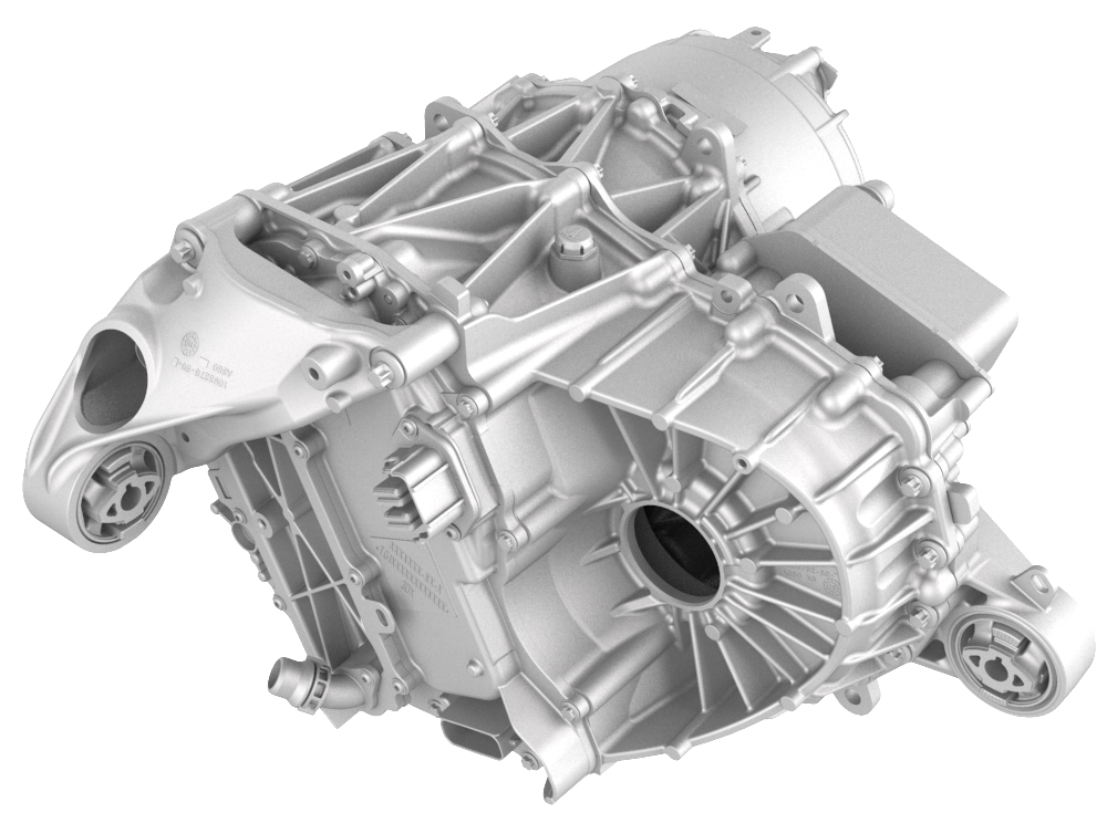
Drive Unit - Rear (Remove and Install)
Correction code 4001100140011001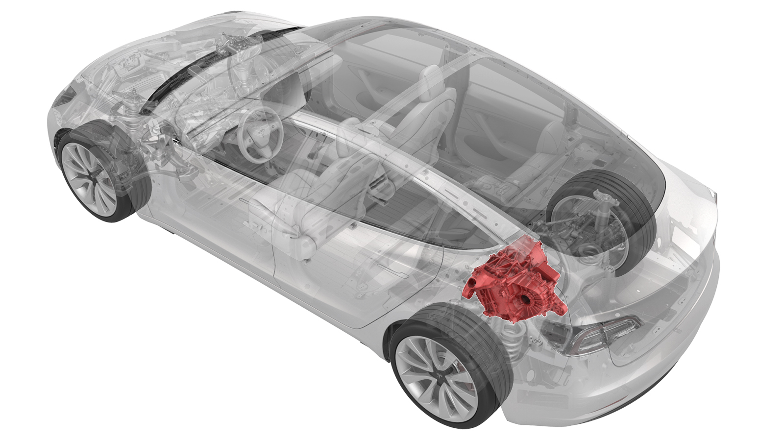
- 1099645-00-BFixture, Subframe, Model 3
- 1130279-00-ALifting Sling, Drive Unit, Model 3 (NA, APAC)
- 1130481-00-AAdapter, Subframe, Body Shop, Model 3
- 1096075-00-ATool, Hub Puller, Hydraulic
- 1133386-00-ATool, Axle Extraction, Model 3
- 1140311-00-ALever Lock, HV Connector, Model 3
- 1446276-00-BKit, Drive Unit Dipstick, Model 3
SPECIAL TOOLS
Fixture, Subframe, Model 3 (1099645-00-B) |
Lifting Sling, Drive Unit, Model 3 (NA, APAC) (1130279-00-A) |
Adapter, Subframe, Body Shop, Model 3 (1130481-00-A) |
Tool, Hub Puller, Hydraulic (1096075-00-A) |
Tool, Axle Extraction, Model 3 (1133386-00-A) |
Lever Lock, HV Connector, Model 3 (1140311-00-A) |
Kit, Drive Unit Dipstick, Model 3 (1446276-00-B) |
Remove
-
Disconnect the electrical harness from the inverter low voltage connector.
-
Release the clip that attaches the low voltage electrical harness to the inverter.
-
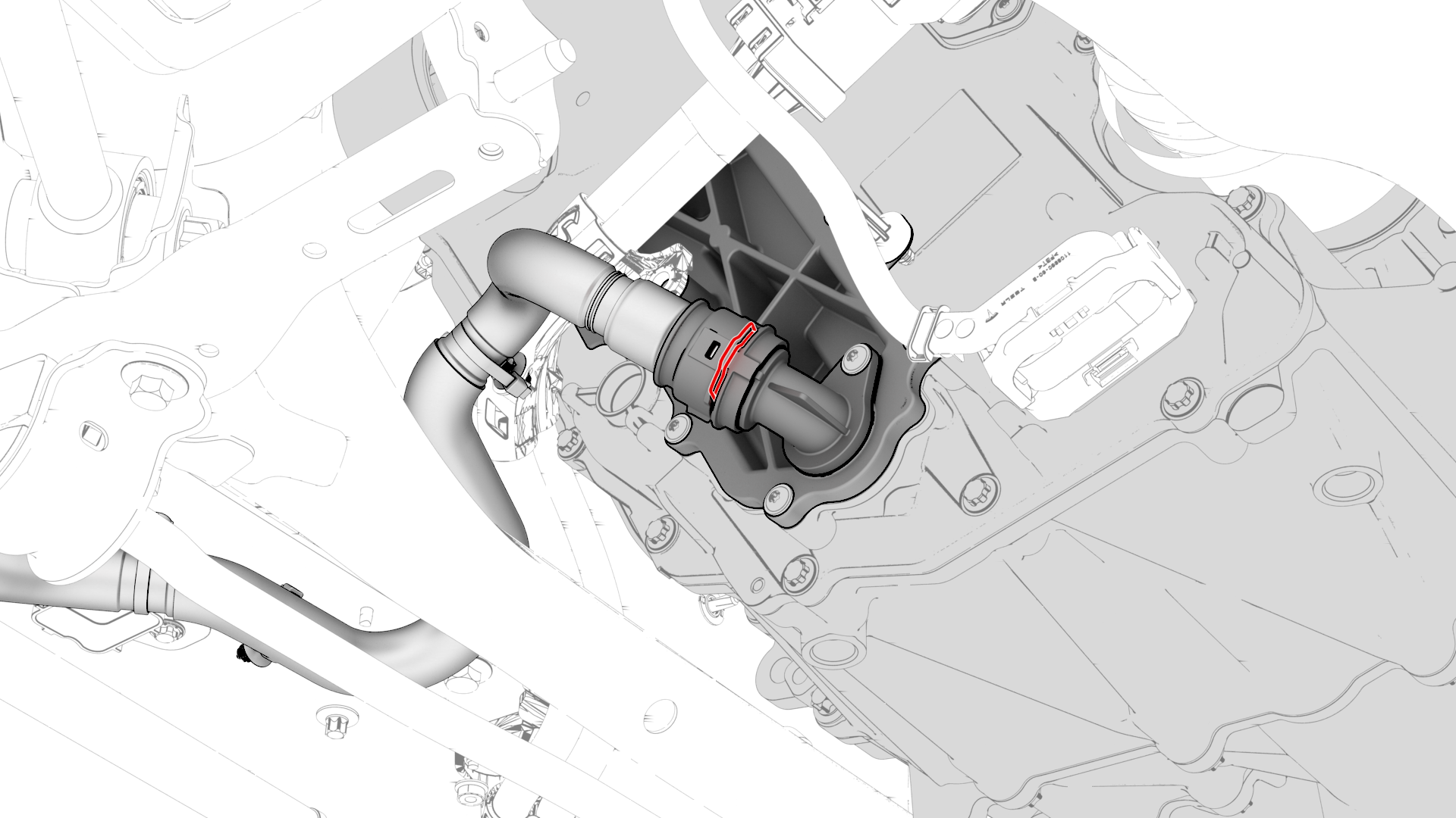
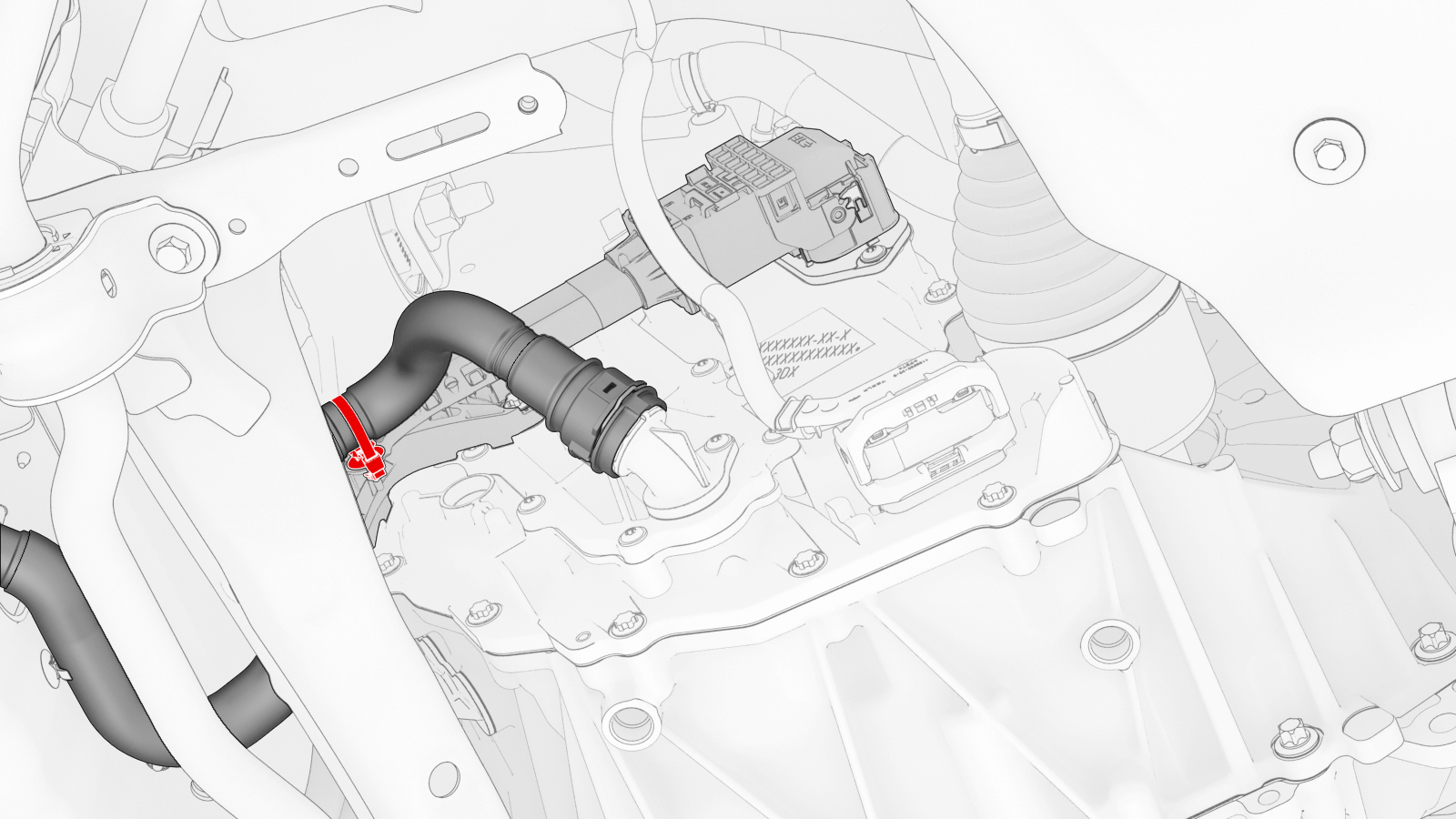
Release the clip, disconnect the rear drive unit inlet hose from the inverter coolant inlet, and then plug the inlet.
-
Release the clip that attaches the rear drive unit inlet hose to the HV harness bracket, and then remove the hose from the rear drive unit.
-
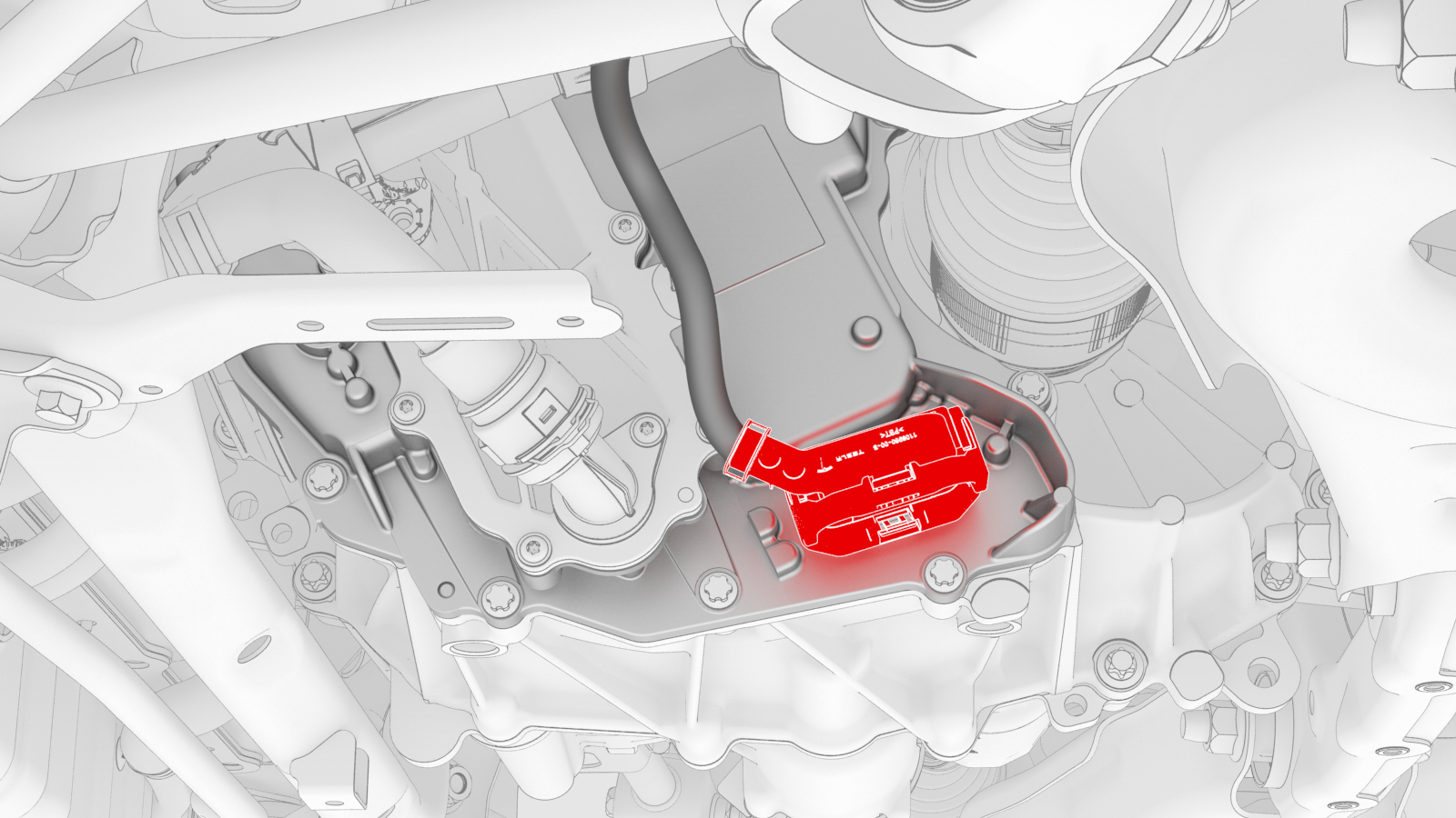
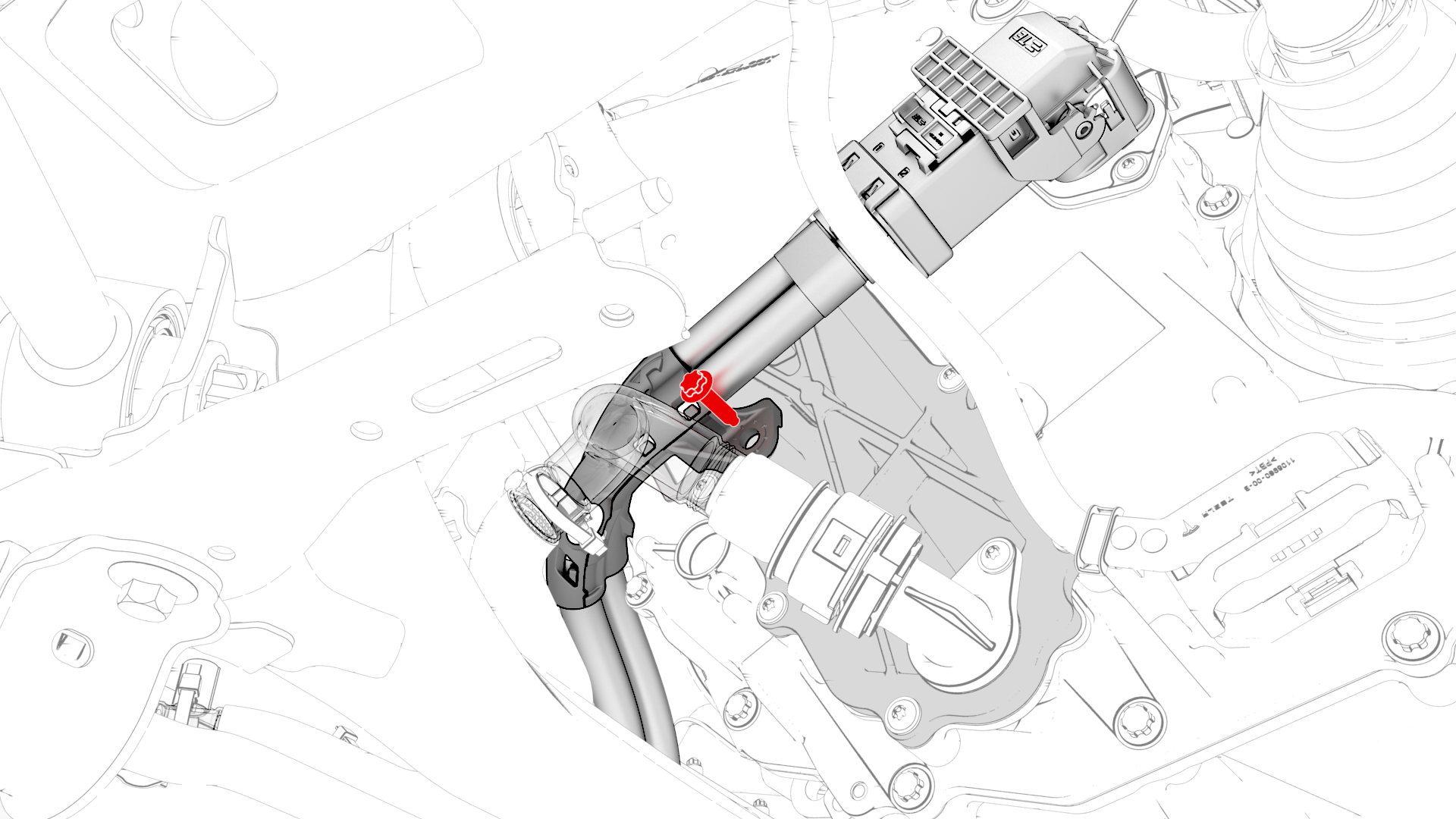
Remove the bolt that attaches the HV harness bracket to the inverter.
-
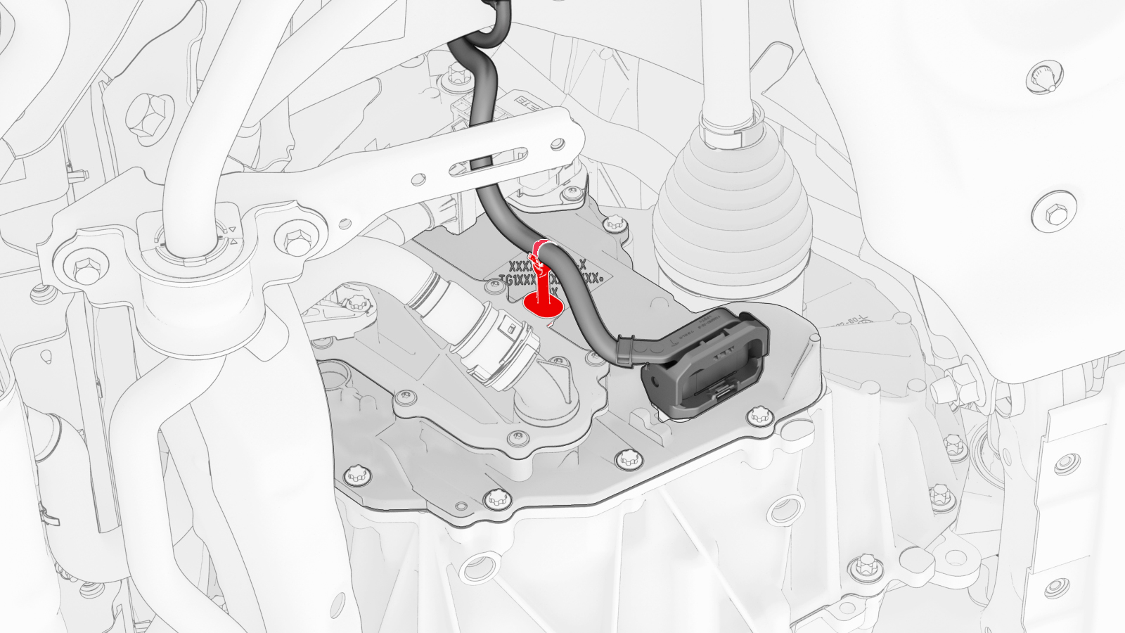
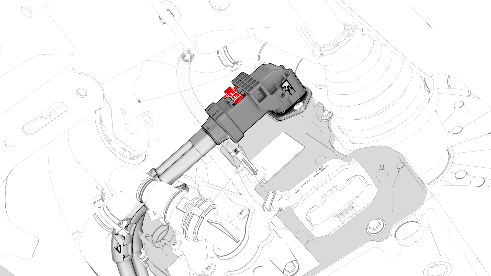
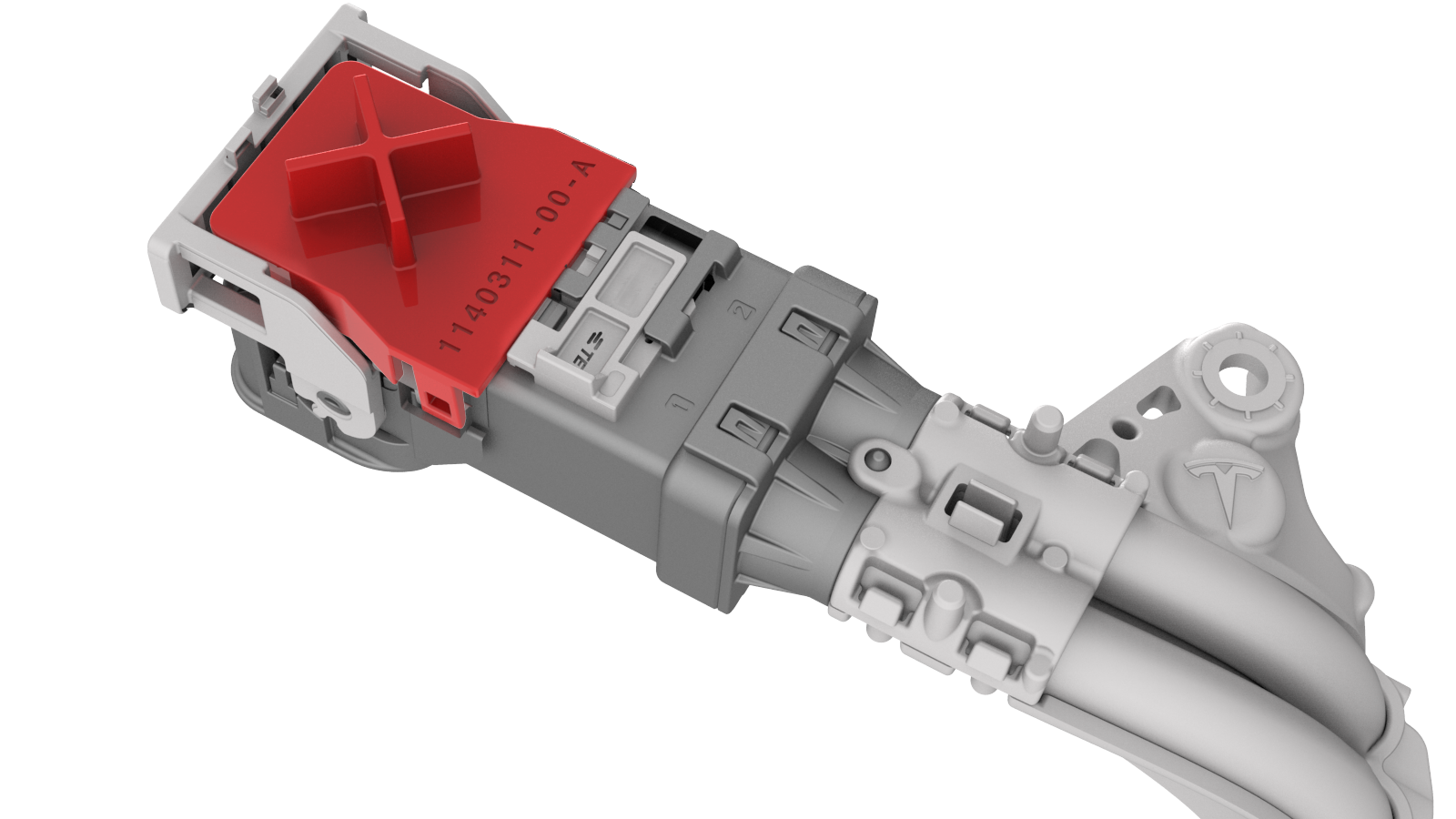
Slide the release to unlock the HV harness connector.
-
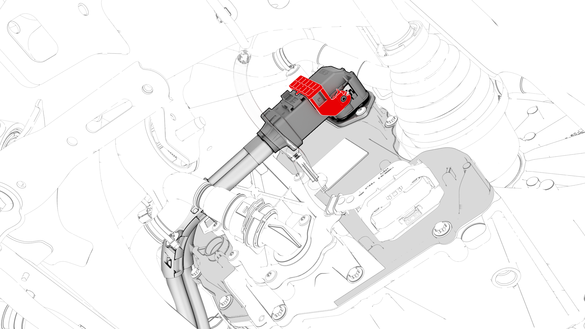
Lift the handle on HV harness connector, disconnect the harness from the inverter connector, and then remove the harness from the rear drive unit.
-
Release the clip that attaches the LH rear ABS wheel speed sensor connector to the subframe, and then disconnect the subframe harness from the connector.
 Tip: Use a mechanical pickup tool to hold the connector in place, and then release the connector clip with a screwdriver.
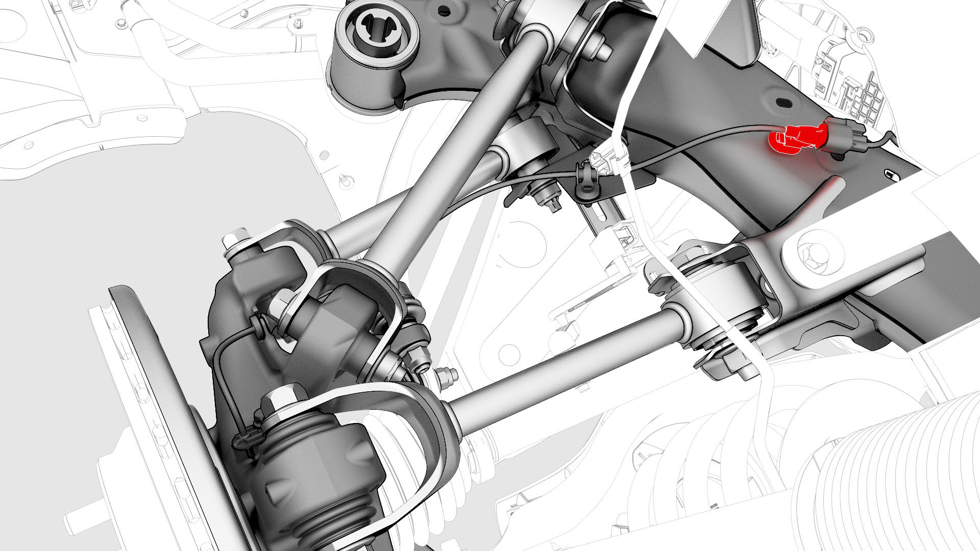
-
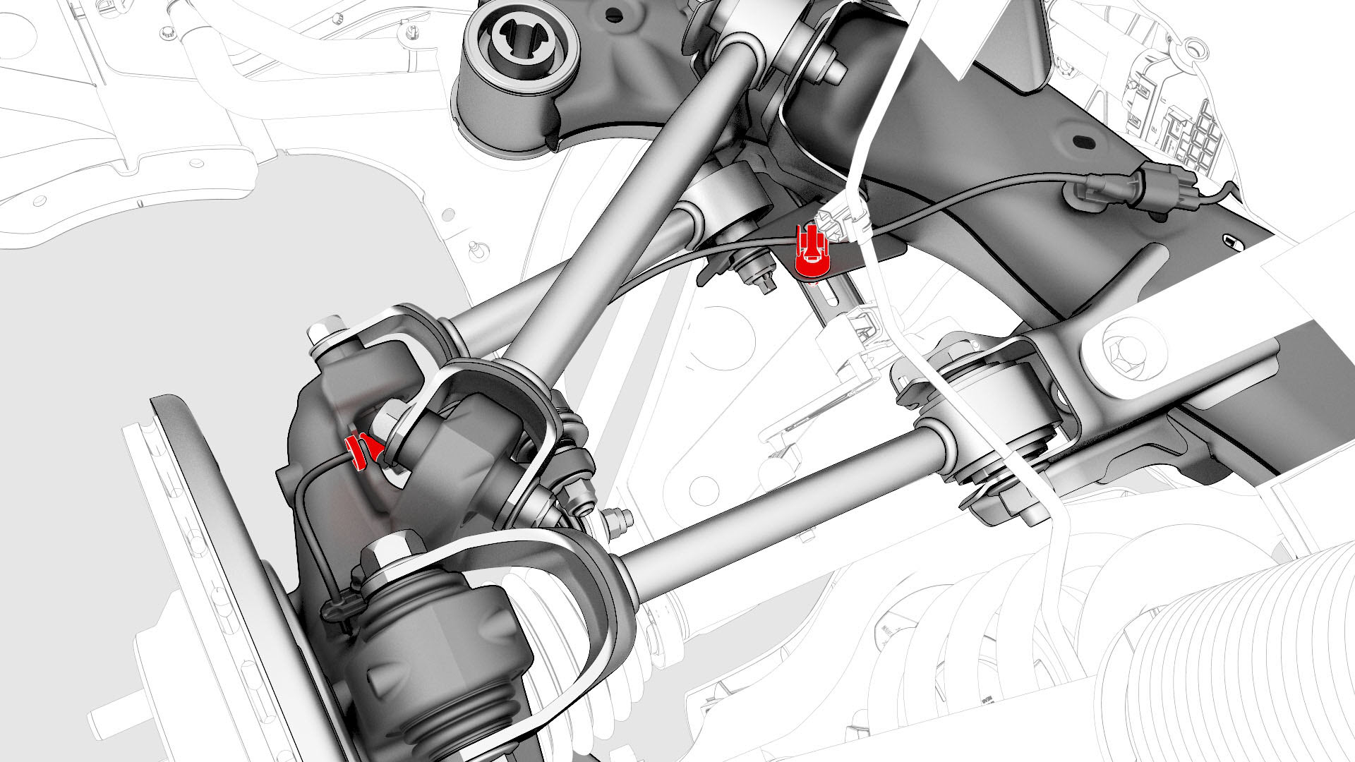
Release the clip and remove the grommet that attach the rear LH ABS wheel speed sensor cable to the rear knuckle and bracket.
-
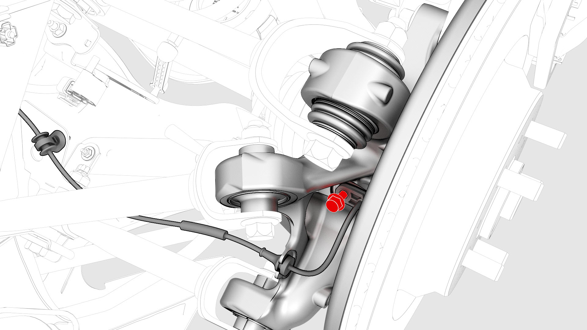
Remove and discard the bolt that attaches the rear LH ABS wheel speed sensor to the knuckle, and then remove the sensor from the knuckle.
-
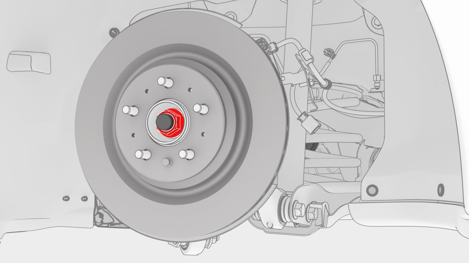
Remove and discard the nut,
and then remove the washer that attach the LH halfshaft to the hub
assembly.
-
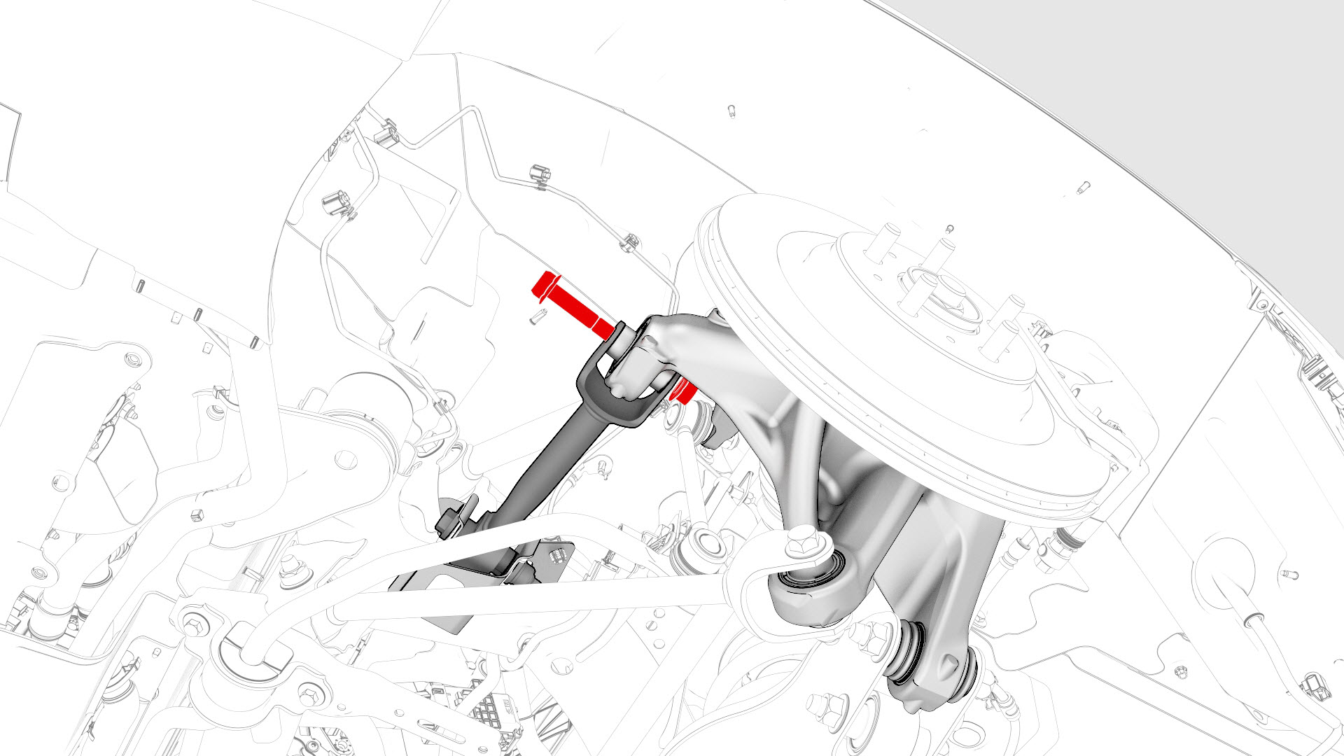
Remove the bolt that attaches the LH rear brake rotor to the hub.
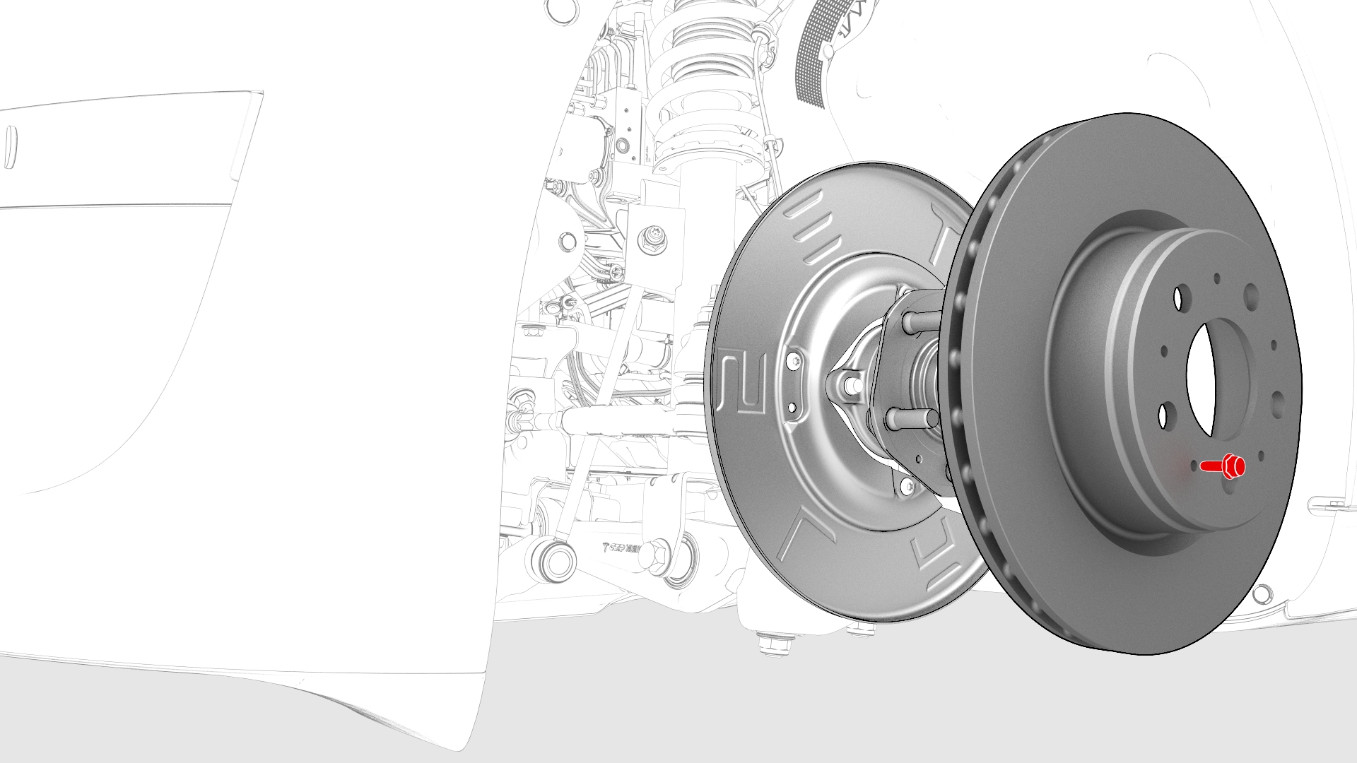 Note: Remove the lug nut previously installed for early production vehicles.
 -
Install the bolt that attaches the LH brake rotor to the hub.
 Torque 5 NmNote: Reinstall the lug nut previously installed for early production vehicles.
 -
Remove the bolt and nut that attach the LH upper aft link to the knuckle.
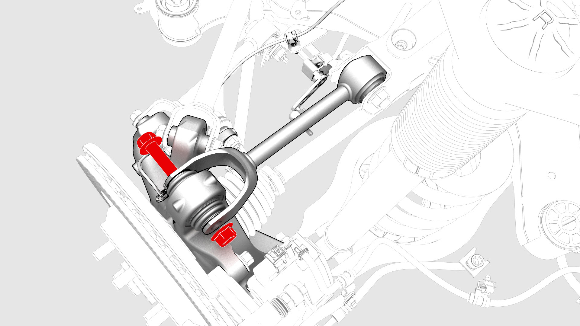
-
Remove the bolt and nut that attach the LH upper fore link to the knuckle.
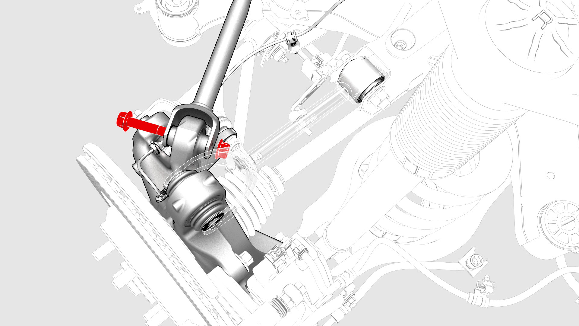
-
Remove the bolt and nut that attach the LH rear toe link to the knuckle.
-
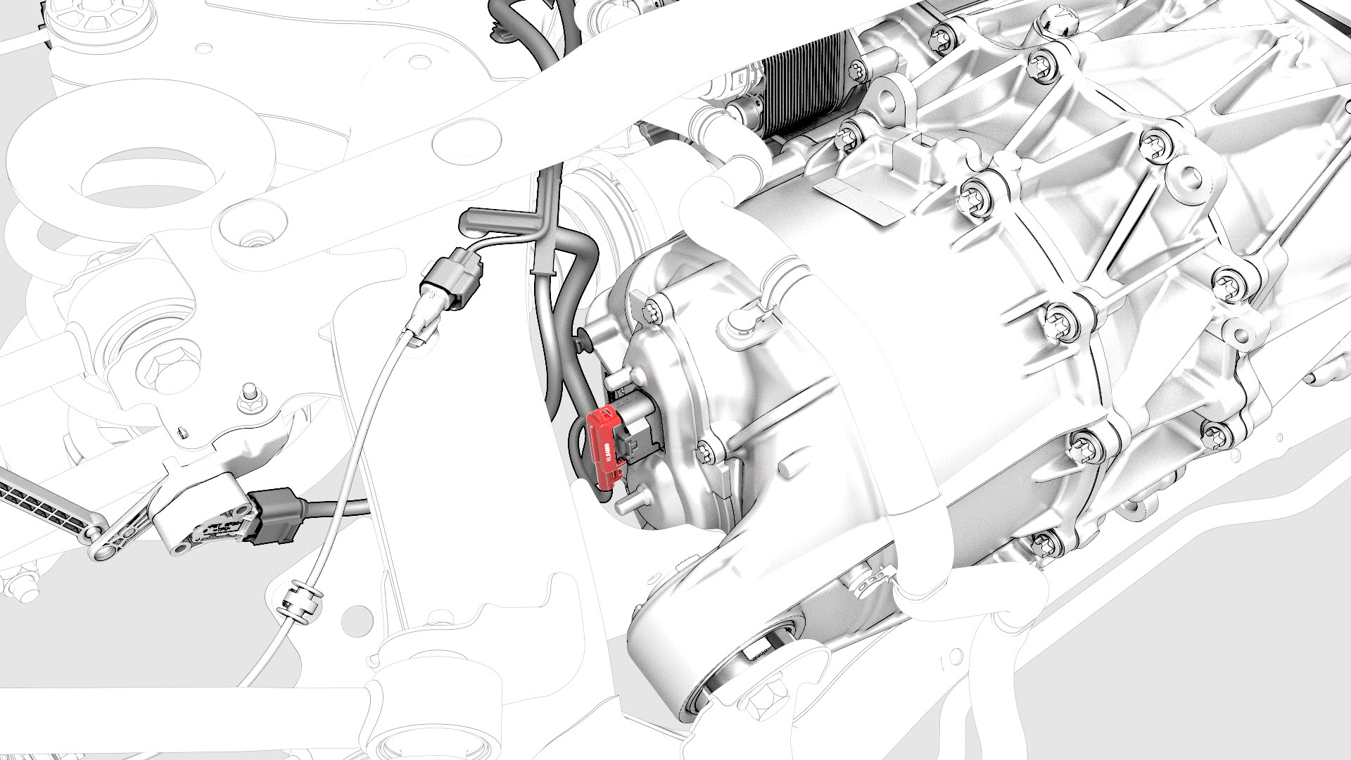
Disconnect the electrical harness from the resolver connector.
-
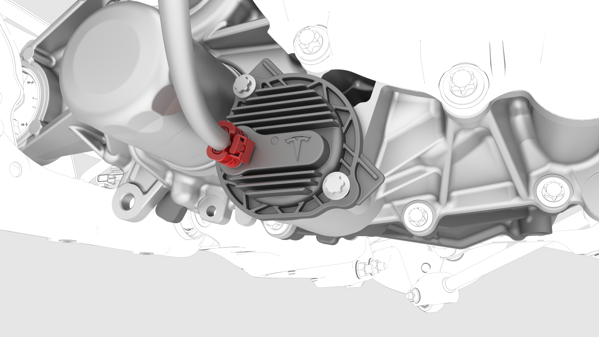
Disconnect the electrical harness from the oil pump connector.
-
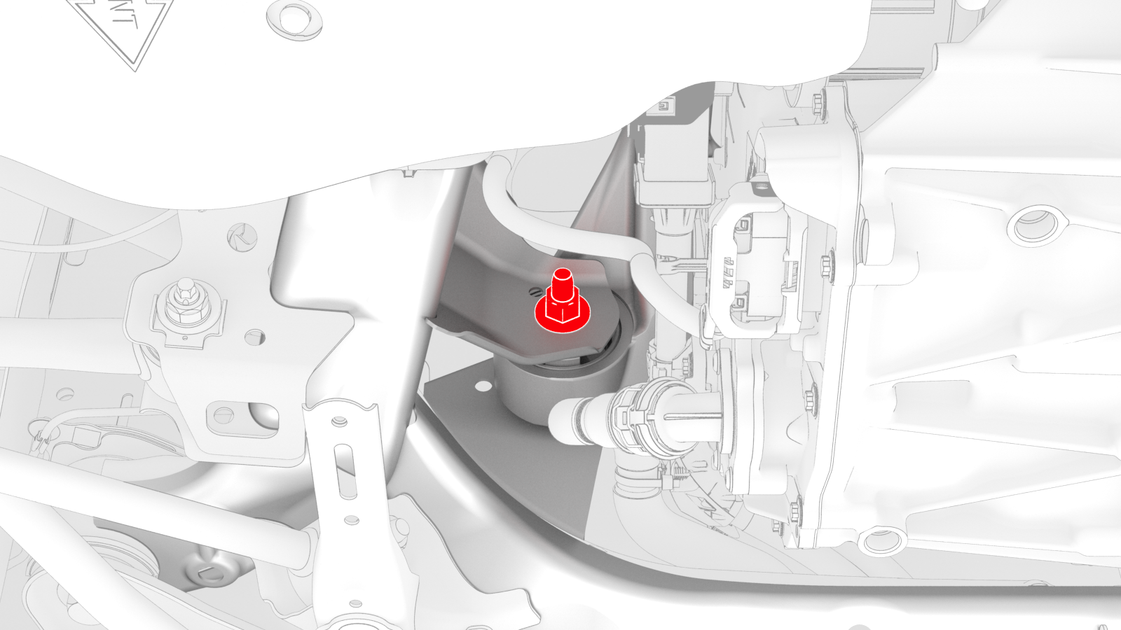
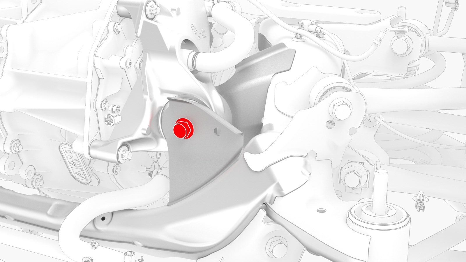
Remove the bolt and nut that
attach the LH mount of the rear drive unit to the rear subframe.
-
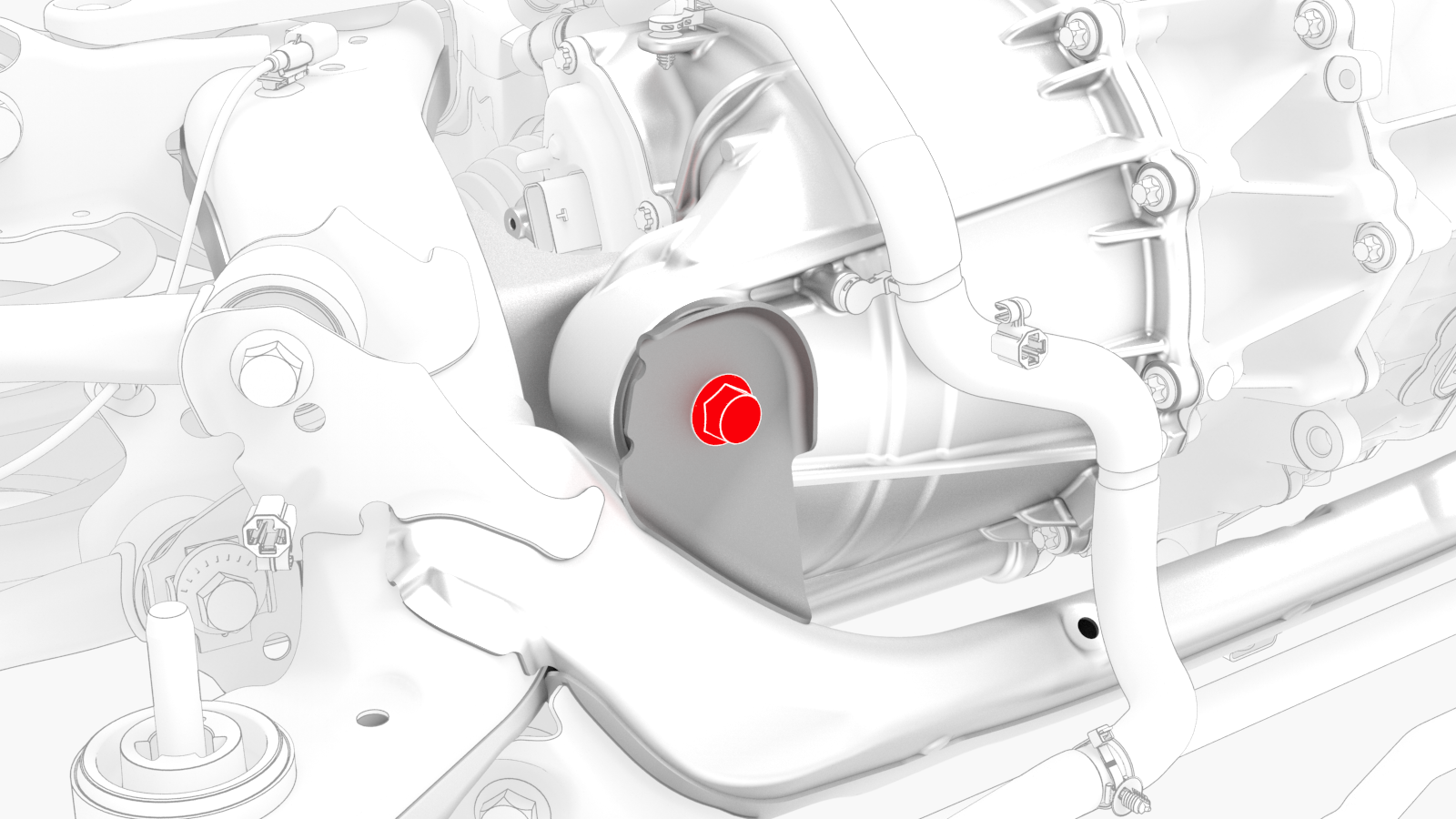
Remove the bolt and nut that
attach the RH bushing of the rear drive unit to the rear subframe.
-
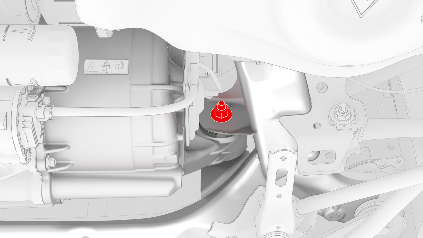
Remove the bolt and nut that
attach the rear bushing of the rear drive unit to the rear subframe.
-
Remove the drive unit sling tool from the rear drive unit.
| 1 | Remove the rear subframe assembly. See Subframe Assembly - Rear (Remove and Install). | ||
| 2 | Disconnect the electrical harness from the inverter low voltage connector. | |
| 3 | Release the clip that attaches the low voltage electrical harness to the inverter. | |
| 4 | Release the clip, disconnect the rear drive unit inlet hose from the inverter coolant inlet, and then plug the inlet. | |
| 5 | Release the clip that attaches the rear drive unit inlet hose to the HV harness bracket, and then remove the hose from the rear drive unit. | |
| 6 | Remove the bolt that attaches the HV harness bracket to the inverter. | |
| 7 | Slide the release to unlock the HV harness connector. | |
| 8 | Lift the handle on HV harness connector, disconnect the harness from the inverter connector, and then remove the harness from the rear drive unit. | |
| 9 | Drain the fluid from the rear drive unit. See Gearbox Fluid - Rear Drive Unit (Drain and Refill). | ||
| 10 | Release the clip that attaches the LH rear ABS wheel speed sensor connector to the subframe, and then disconnect the subframe harness from the connector.Tip: Use a mechanical pickup tool to hold the connector in place, and then release the connector clip with a screwdriver. | |
| 11 | Release the clip and remove the grommet that attach the rear LH ABS wheel speed sensor cable to the rear knuckle and bracket. | |
| 12 | Remove and discard the bolt that attaches the rear LH ABS wheel speed sensor to the knuckle, and then remove the sensor from the knuckle. | |
| 13 | Remove and discard the nut, and then remove the washer that attach the LH halfshaft to the hub assembly. | |
| 14 | Remove the bolt that attaches the LH rear brake rotor to the hub. Note: Remove the lug nut previously installed for early production vehicles.
| |
| 15 | Install the hub puller onto the LH rear rotor, and then install and hand-tighten the puller washers (x5) and the lug nuts (x5) onto the rotor studs. | ||
| 16 | Use the hub puller to free the LH rear halfshaft from the hub splines. Note: The LH rear halfshaft is removed in a later step.
| ||
| 17 | Remove the lug nuts (x5) and the puller washers (x5) from the LH rear rotor studs, and then remove the hub puller from the rotor. | ||
| 18 | Install the bolt that attaches the LH brake rotor to the hub. Torque 5 Nm Note: Reinstall the lug nut previously installed for early production vehicles.
| |
| 19 | Remove the bolt and nut that attach the LH upper aft link to the knuckle. | |
| 20 | Remove the bolt and nut that attach the LH upper fore link to the knuckle. | |
| 21 | Remove the bolt and nut that attach the LH rear toe link to the knuckle. | |
| 22 | Remove the LH rear halfshaft from the knuckle and hub assembly. | ||
| 23 | With an assistant, release
the LH rear halfshaft from the rear drive unit. Note: Set the LH rear halfshaft on the LH aft lower control arm.
| ||
| 24 | Remove the LH halfshaft from the rear drive unit, and then install a halfshaft plug into the opening of the gearbox. | ||
| 25 | Repeat step 10 through step 24 on the RH side of the rear drive unit. | ||
| 26 | Disconnect the electrical harness from the resolver connector. | |
| 27 | Disconnect the electrical harness from the oil pump connector. | |
| 28 | Attach the drive unit sling tool to the rear drive unit. | ||
| 29 | Position the drive unit stand underneath the gantry. | ||
| 30 | Attach the drive unit sling tool to the gantry. | ||
| 31 | Raise the sling tool so that there is a slight tension on the cables. | ||
| 32 | Remove the bolt and nut that attach the LH mount of the rear drive unit to the rear subframe. | |
| 33 | Remove the bolt and nut that attach the RH bushing of the rear drive unit to the rear subframe. | |
| 34 | Remove the bolt and nut that attach the rear bushing of the rear drive unit to the rear subframe. | |
| 35 | Raise the drive unit sling tool to lift the rear drive unit out of the rear subframe. | ||
| 36 | Lower the rear drive unit into an empty crate or pallet. | ||
| 37 | Remove the drive unit sling tool from the rear drive unit. |
Install
-
Install and hand-tighten the
bolt and nut that attach the rear bushing of the rear drive unit to the rear
subframe.
-
Install and hand-tighten the
bolt and nut that attach the RH bushing of the rear drive unit to the rear
subframe.
-
Install and hand-tighten the
bolt and nut that attach the LH mount of the rear drive unit to the rear
subframe.
-
Tighten the LH mount, RH
bushing, and rear bushing bolts and nuts that attach the rear drive unit to
the rear subframe.
 Torque 70 Nm
 -
Connect the electrical harness to the oil pump connector.
-
Connect the electrical harness to the resolver connector.
-
With an assistant, hand-tighten the bolt and nut that attach the LH toe link to the knuckle.
Note: The bolt and nut will be tightened to specification during the Four Wheel Alignment (Check and Adjust) at the end of the Front Subframe Assembly (Remove and Install) procedure.
-
With an assistant, hand-tighten the bolt and nut that attach LH upper fore link to the knuckle.
Note: The bolt and nut will be tightened to specification during the Four Wheel Alignment (Check and Adjust) at the end of the Front Subframe Assembly (Remove and Install) procedure.
-
With an assistant, hand-tighten the bolt and nut that attach the upper aft link to the knuckle.
Note: The bolt and nut will be tightened to specification during the Four Wheel Alignment (Check and Adjust) at the end of the Front Subframe Assembly (Remove and Install) procedure.
-
Install the washer, and install a new nut to attach the halfshaft to the LH rear hub.
 Torque 245 Nm
 -
Install the rear LH ABS wheel speed sensor to the knuckle, and then install a new bolt to attach the sensor to the knuckle.
 Torque 5 Nm
 -
Fasten the clip and install the grommet that attach the rear LH ABS wheel speed sensor cable to the rear LH knuckle and bracket.
 Caution:Perform a push-pull check on the clip and grommet to make sure they are securely fastened to the knuckle and bracket.
 -
Connect the subframe harness
to the rear LH ABS wheel speed sensor connector, and then fasten the clip
that attaches the connector to the rear subframe.
-
Attach the HV connector lever lock onto the back of the HV electrical harness.
-
Firmly connect the HV electrical harness to the inverter connector.
Caution:Make sure that the harness fits the connector squarely and tightly.
-
While pressing the harness to the connector, fully lower the handle.
-
Slide the release to lock the HV electrical harness.
-
Install the bolt that attaches the HV harness bracket to the inverter.
 Torque 6 Nm
 -
Connect the rear drive unit inlet hose to the inverter coolant inlet, and then fasten the clip.
Caution:Perform a push-pull test to verify that the hose is fully seated.
-
Fasten the clip that attaches the rear drive unit inlet hose to the HV harness bracket.
-
Connect the electrical harness to the inverter low voltage connector.
-
Fasten the clip that attaches the low voltage electrical harness to the inverter.
| 1 | Attach the drive unit sling tool to the new rear drive unit. | ||
| 2 | Raise the new rear drive unit out of the crate. | ||
| 3 | Move the new rear drive unit over the rear subframe. | ||
| 4 | With an assistant, lower the drive unit sling tool to install the new rear drive unit into the rear subframe. | ||
| 5 | Install and hand-tighten the bolt and nut that attach the rear bushing of the rear drive unit to the rear subframe. | |
| 6 | Install and hand-tighten the bolt and nut that attach the RH bushing of the rear drive unit to the rear subframe. | |
| 7 | Install and hand-tighten the bolt and nut that attach the LH mount of the rear drive unit to the rear subframe. | |
| 8 | Lower the drive unit sling tool to release the tension on the cables. | ||
| 9 | Remove the drive unit sling tool from the gantry. | ||
| 10 | Remove the drive unit sling tool from the rear drive unit. | ||
| 11 | Tighten the LH mount, RH
bushing, and rear bushing bolts and nuts that attach the rear drive unit to
the rear subframe. Torque 70 Nm | ||
| 12 | Connect the electrical harness to the oil pump connector. | |
| 13 | Connect the electrical harness to the resolver connector. | |
| 14 | Remove the halfshaft plug from the gearbox, and then install the LH halfshaft to the rear drive unit. Note: New drive units come
prefilled with gearbox fluid that might leak out of the drive unit
during this step. Make sure to clean up any leakage.
Note: Set the LH halfshaft on the aft lower control arm.
| ||
| 15 | Install the LH halfshaft to the hub and knuckle assembly. | ||
| 16 | With an assistant, hand-tighten the bolt and nut that attach the LH toe link to the knuckle. Note: The bolt and nut will
be tightened to specification during the Four Wheel Alignment (Check and
Adjust) at the end of the Front Subframe Assembly (Remove and Install)
procedure.
| |
| 17 | With an assistant, hand-tighten the bolt and nut that attach LH upper fore link to the knuckle. Note: The bolt and nut will
be tightened to specification during the Four Wheel Alignment (Check and
Adjust) at the end of the Front Subframe Assembly (Remove and Install)
procedure.
| |
| 18 | With an assistant, hand-tighten the bolt and nut that attach the upper aft link to the knuckle. Note: The bolt and nut will
be tightened to specification during the Four Wheel Alignment (Check and
Adjust) at the end of the Front Subframe Assembly (Remove and Install)
procedure.
| |
| 19 | Install the washer, and install a new nut to attach the halfshaft to the LH rear hub. Torque 245 Nm | |
| 20 | Install the rear LH ABS wheel speed sensor to the knuckle, and then install a new bolt to attach the sensor to the knuckle. Torque 5 Nm | |
| 21 | Fasten the clip and install the grommet that attach the rear LH ABS wheel speed sensor cable to the rear LH knuckle and bracket. Caution: Perform a push-pull check on the clip and grommet to make sure they are securely fastened to the knuckle and bracket.
| |
| 22 | Connect the subframe harness to the rear LH ABS wheel speed sensor connector, and then fasten the clip that attaches the connector to the rear subframe. | |
| 23 | Repeat step 14 through 22 on the RH side of the rear drive unit. | ||
| 24 | Fully raise the handle on the rear drive unit HV electrical harness. | ||
| 25 | Attach the HV connector lever lock onto the back of the HV electrical harness. | |
| 26 | Firmly connect the HV electrical harness to the inverter connector. Caution: Make sure that the harness fits the connector squarely and tightly.
| ||
| 27 | While pressing the harness to the connector, remove the HV connector lever lock. | ||
| 28 | While pressing the harness to the connector, fully lower the handle. | |
| 29 | Slide the release to lock the HV electrical harness. | |
| 30 | Install the bolt that attaches the HV harness bracket to the inverter. Torque 6 Nm | |
| 31 | Connect the rear drive unit inlet hose to the inverter coolant inlet, and then fasten the clip. Caution: Perform a push-pull test to verify that the hose is fully seated.
| |
| 32 | Fasten the clip that attaches the rear drive unit inlet hose to the HV harness bracket. | |
| 33 | Connect the electrical harness to the inverter low voltage connector. | |
| 34 | Fasten the clip that attaches the low voltage electrical harness to the inverter. | |
| 35 | Install the rear subframe assembly. See Subframe Assembly - Rear (Remove and Install). |