DC Input Assembly - HV Battery (Remove and Replace)
Correction code 1630210116302101
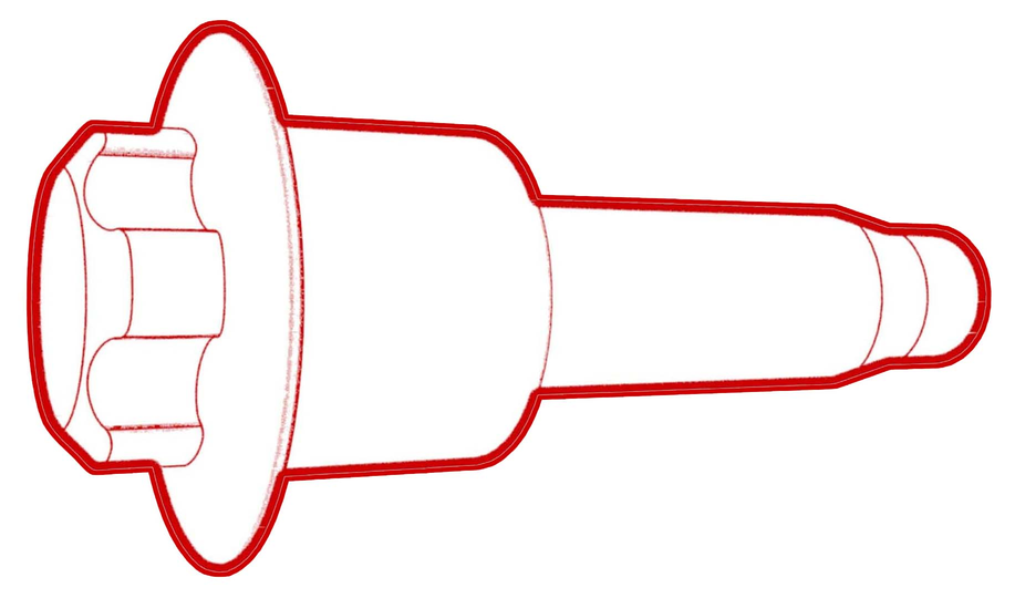
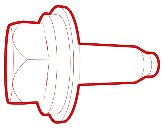
- 1057602-00-ARatchet, 1/4" Sq Dr, HV Insulated
- 1057606-00-ASkt, 1/4" Sq Dr, 13mm, HV Insulated
- 1057607-00-AMagnet, Flexible, HV Insulated, 18"
- 1059330-00-BSkt, 1/4in Dr, 5-Lobe Torx Plus External
- 1076927-00-AResistance meter, microohm, Hioki RM 3548
SPECIAL TOOLS
Ratchet, 1/4" Sq Dr, HV Insulated (1057602-00-A) |
Skt, 1/4" Sq Dr, 13mm, HV Insulated (1057606-00-A) |
Magnet, Flexible, HV Insulated, 18" (1057607-00-A) |
Skt, 1/4in Dr, 5-Lobe Torx Plus External (1059330-00-B) |
Resistance meter, microohm, Hioki RM 3548 (1076927-00-A) |
 Warning:
Only technicians who have been trained in High Voltage Awareness are permitted to perform this procedure. Proper personal protective equipment (PPE) and insulating HV gloves with a minimum rating of class 0 (1000V) must be worn at all times a high voltage cable, busbar, or fitting is handled. Refer to Tech Note TN-15-92-003, "High Voltage Awareness Care Points" for additional safety information.
Remove
-
Remove the insulator for the DC input assembly.
-
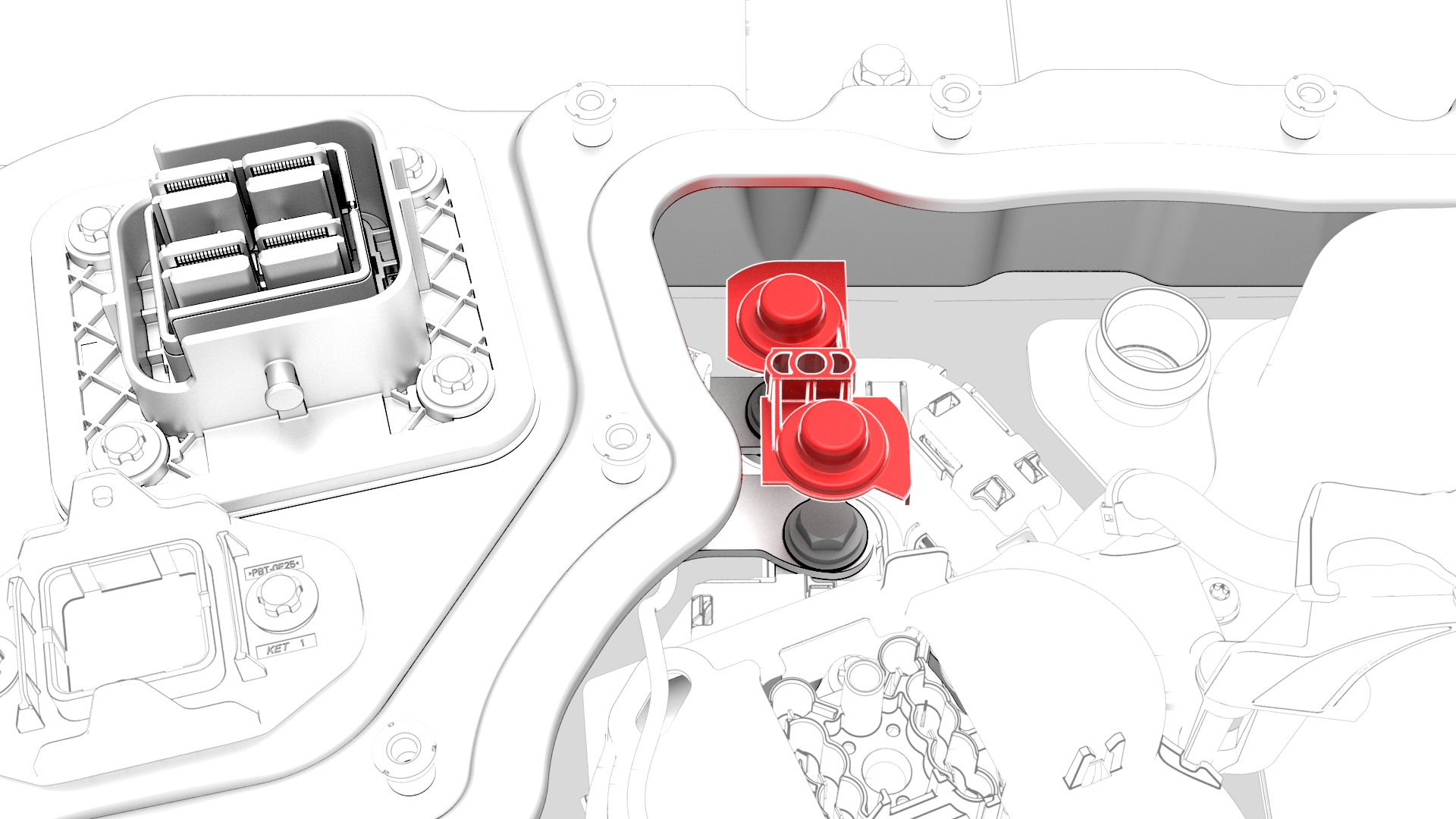
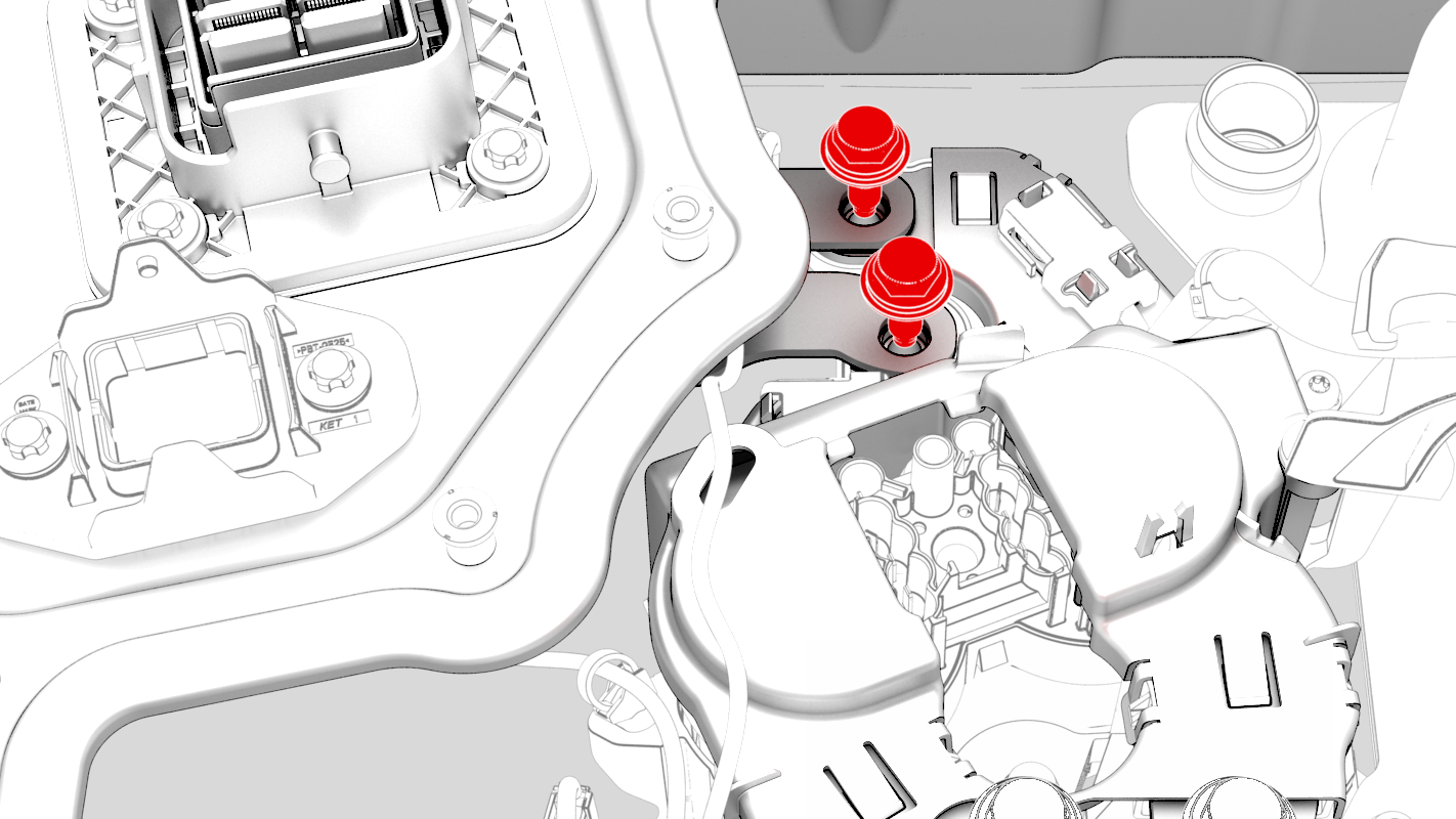
Remove and discard the bolts that attach the DC input busbars to the fast charge contactor busbars.
-
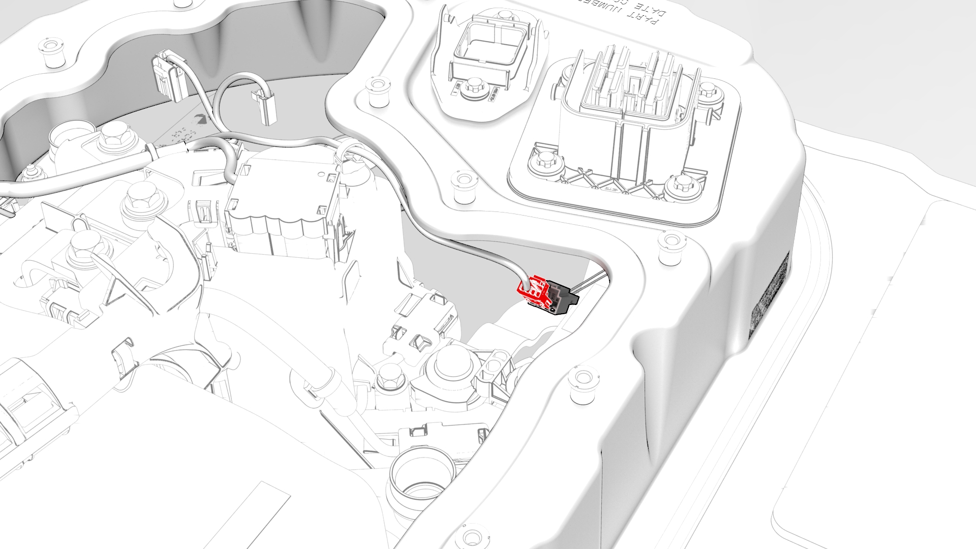
Disconnect the electrical harness from the DC input assembly connector.
-
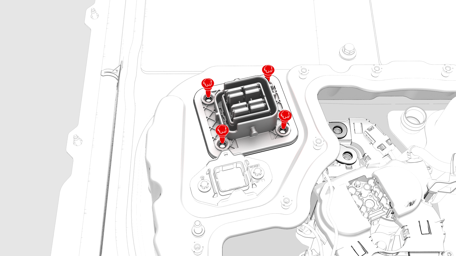
Remove the bolts that attach the DC input assembly to the penthouse, and then remove the DC input assembly from the vehicle.
| 1 | Remove the pyrotechnic battery disconnect from the penthouse. See Pyrotechnic Battery Disconnect (Remove and Replace). | ||
| 2 | Remove the insulator for the DC input assembly. | |
| 3 | Remove and discard the bolts that attach the DC input busbars to the fast charge contactor busbars. | |
| 4 | Disconnect the electrical harness from the DC input assembly connector. | |
| 5 | Remove the bolts that attach the DC input assembly to the penthouse, and then remove the DC input assembly from the vehicle. |
Install
-
Install the DC input assembly to the penthouse, install the bolts (x4) that attach the DC input assembly to the penthouse, and then mark the bolts with a paint pen after they are torqued..
 Torque 6 Nm
 -
Install new bolts (x2) to attach the DC input busbars to the fast charge contactor busbars, and then mark the bolts with a paint pen after they are torqued.
 Torque 9 Nm
 -
Use the Hioki resistance meter to measure the resistance at the HV joint between the positive DC input busbar and the positive (LH) fast charge contactor busbar.
Note: The maximum acceptable resistance is 0.060 mΩ (60 μΩ). If the resistance is above this value, escalate a Toolbox session, as appropriate.
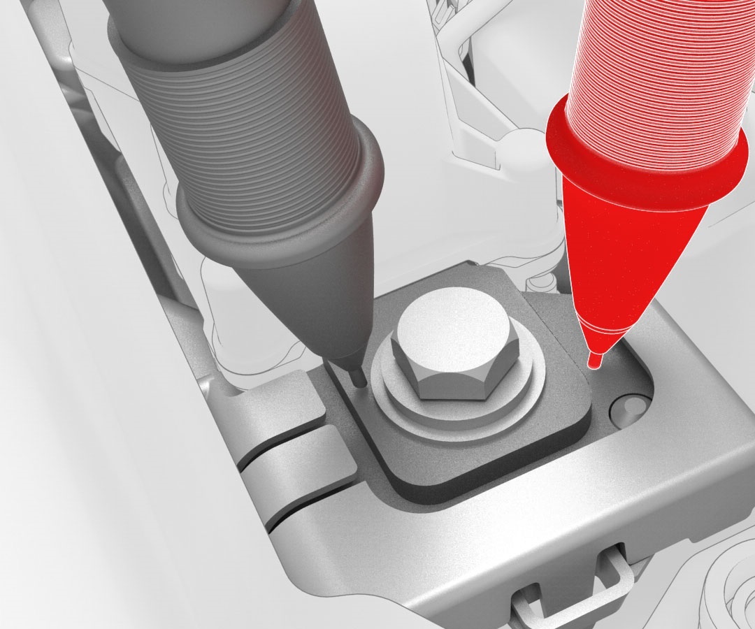 Generic Measurement - Actual busbars and fasteners might appear different
 -
Use the Hioki resistance meter to measure the resistance at the HV joint between the negative DC input busbar and the negative (RH) fast charge contactor busbar.
Note: The maximum acceptable resistance is 0.060 mΩ (60 μΩ). If the resistance is above this value, escalate a Toolbox session, as appropriate.
Generic Measurement - Actual busbars and fasteners might appear different
-
Install the insulator for the DC input assembly.
-
Connect the electrical harness to the DC input assembly connector.
| 1 | Install the DC input assembly to the penthouse, install the bolts (x4) that attach the DC input assembly to the penthouse, and then mark the bolts with a paint pen after they are torqued.. Torque 6 Nm | |
| 2 | Install new bolts (x2) to attach the DC input busbars to the fast charge contactor busbars, and then mark the bolts with a paint pen after they are torqued. Torque 9 Nm | |
Generic Measurement - Actual busbars and fasteners might appear different
| 3 | Use the Hioki resistance meter to measure the resistance at the HV joint between the positive DC input busbar and the positive (LH) fast charge contactor busbar. Note: The maximum acceptable resistance is 0.060 mΩ (60 μΩ). If the resistance is above this value, escalate a Toolbox session, as appropriate.
| |
Generic Measurement - Actual busbars and fasteners might appear different
| 4 | Use the Hioki resistance meter to measure the resistance at the HV joint between the negative DC input busbar and the negative (RH) fast charge contactor busbar. Note: The maximum acceptable resistance is 0.060 mΩ (60 μΩ). If the resistance is above this value, escalate a Toolbox session, as appropriate.
| |
| 5 | Install the insulator for the DC input assembly. | |
| 6 | Connect the electrical harness to the DC input assembly connector. | |
| 7 | Install the pyrotechnic battery disconnect into the penthouse. See Pyrotechnic Battery Disconnect (Remove and Replace). |