Drive Unit - Front (Remove and Replace)
Correction code 3901210239012102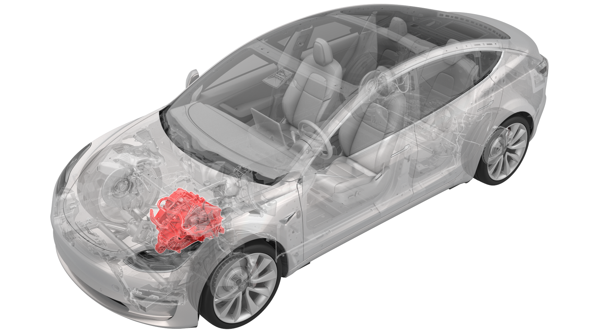
- 1133386-00-ATool, Axle Extraction, Model 3
- 1130279-00-ALifting Sling, Drive Unit, Model 3 (NA, APAC)
- 1130279-01-ALifting Sling, Drive Unit, Model 3 (EMEA)
SPECIAL TOOLS
Tool, Axle Extraction, Model 3 (1133386-00-A) |
Lifting Sling, Drive Unit, Model 3 (NA, APAC) (1130279-00-A) |
Lifting Sling, Drive Unit, Model 3 (EMEA) (1130279-01-A) |
Remove
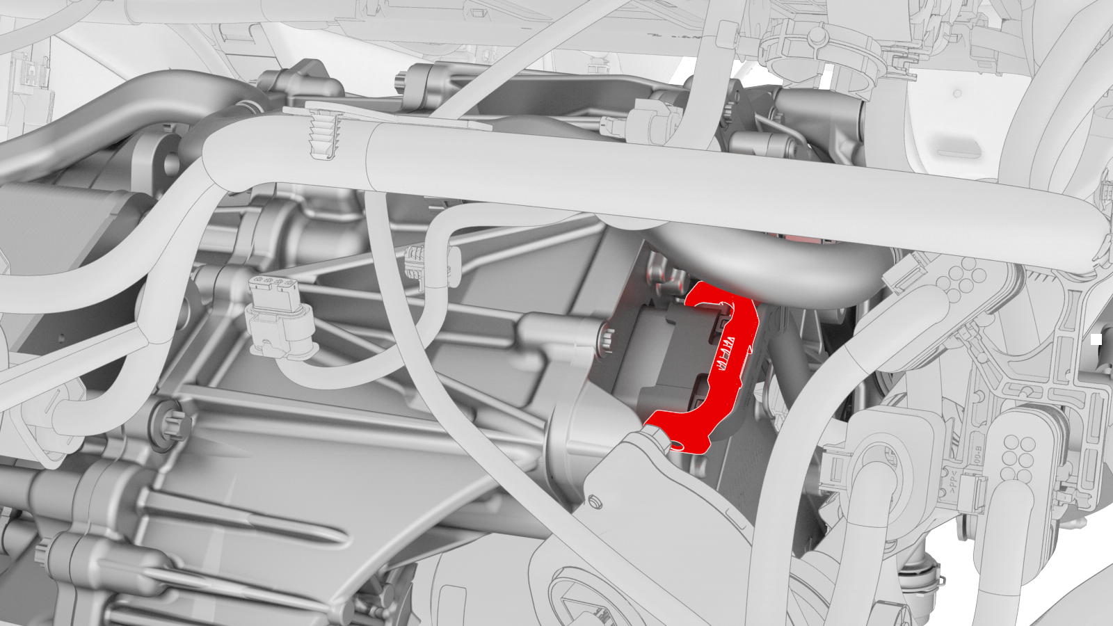
-
Release the locking tab, and then push the handle downward to disconnect the front drive unit inverter logic connector.
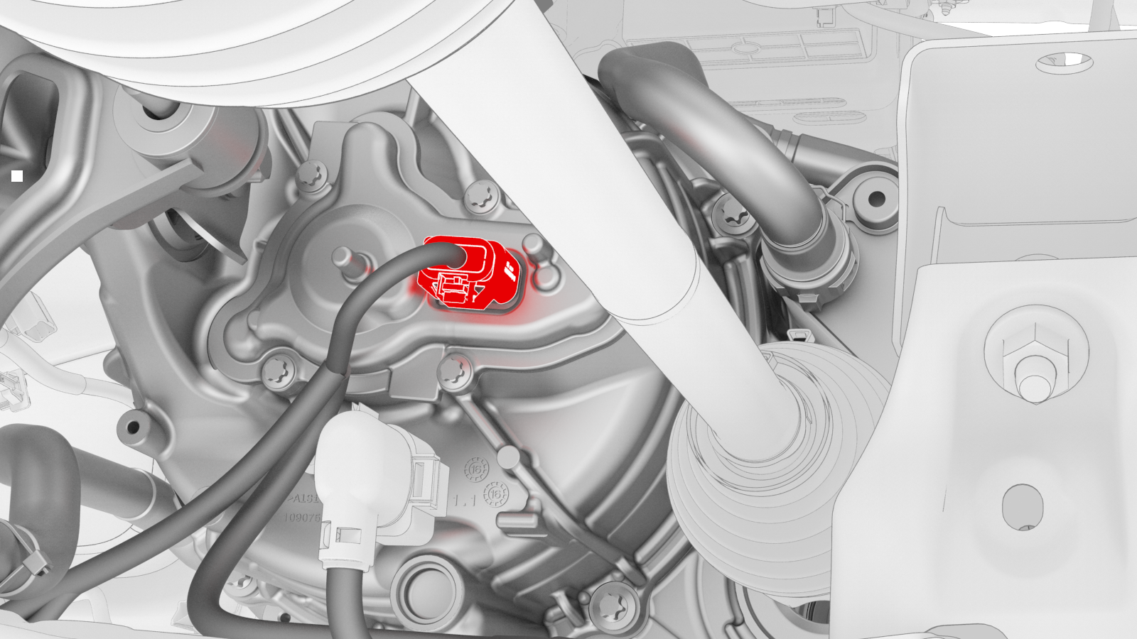
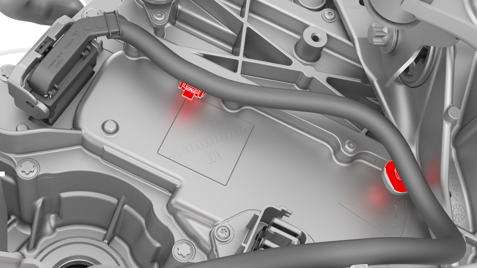
-
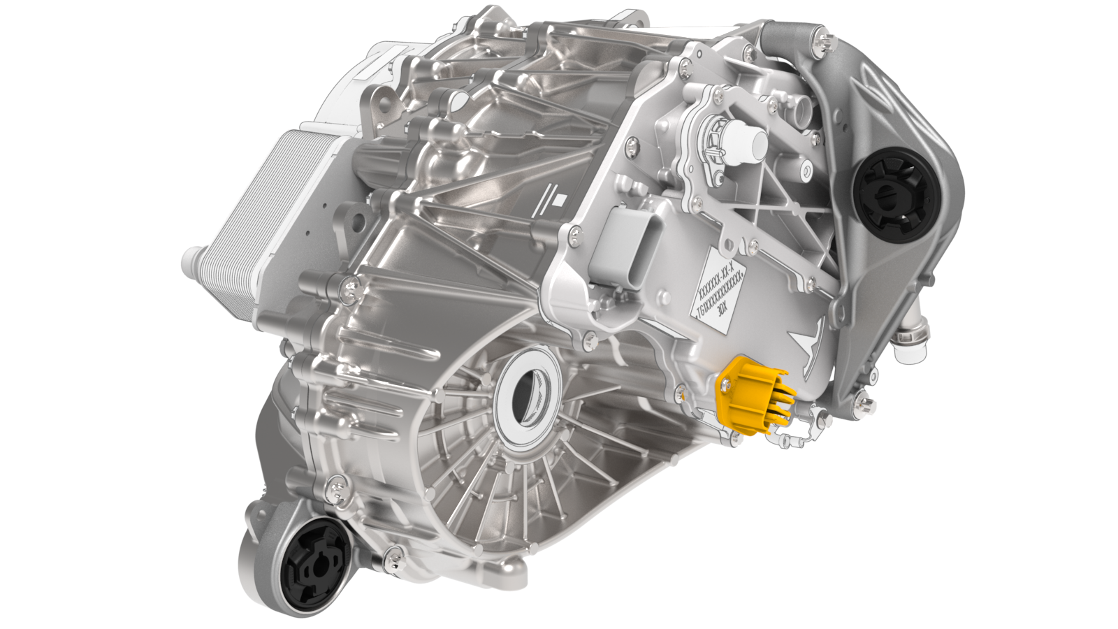
Release the red locking tab, and then press down on the tab to disconnect the resolver logic connector.
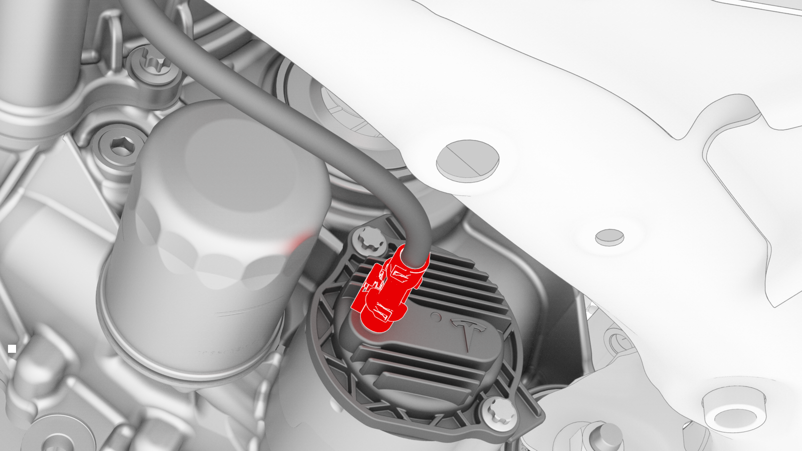
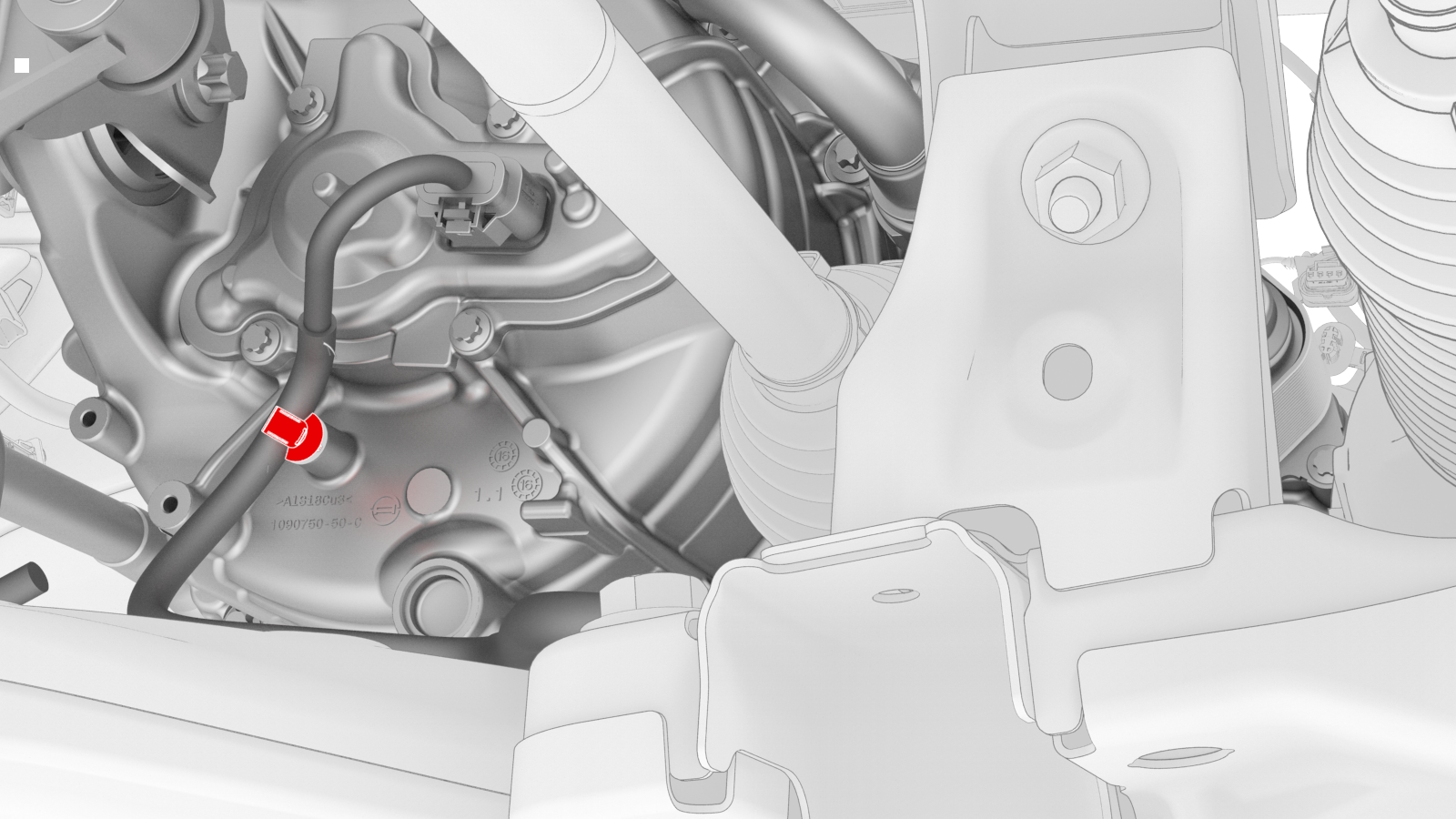
-
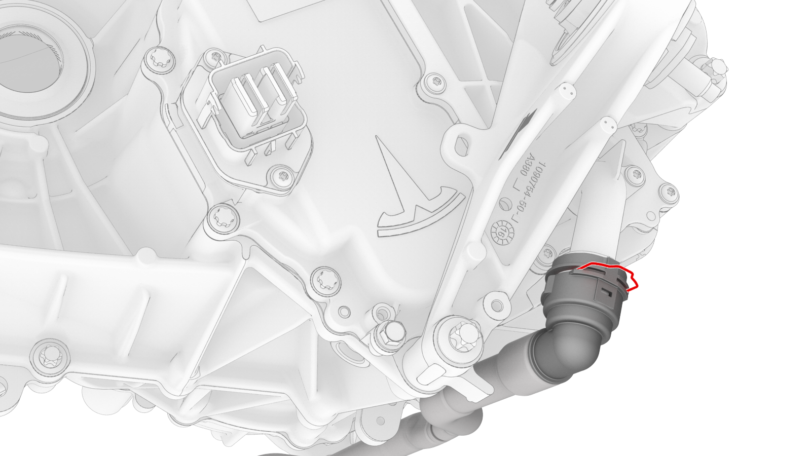
Release the grey locking tab, and then press down on the tab to disconnect the oil pump connector.
-
Release the clip that attaches the front drive unit harness to the front drive unit motor.
-
Release the clips that attach the front drive unit harness to the front drive unit inverter.
-
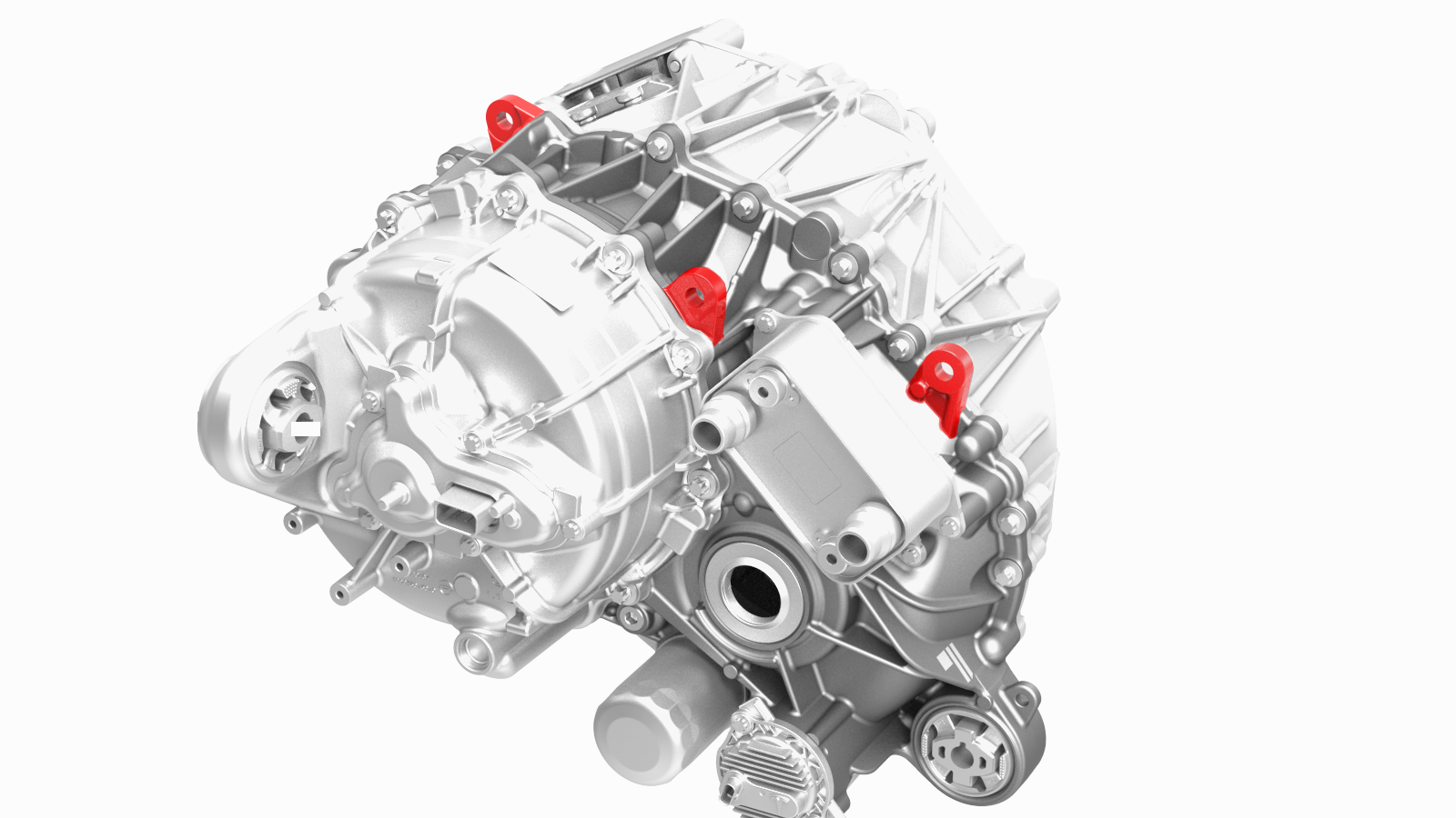
Install the drive unit sling hooks on the front drive unit.
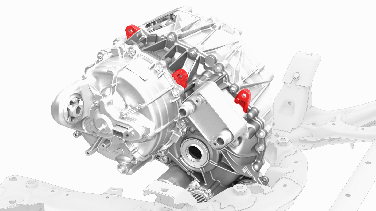 Front drive unit sling hook locations
 -
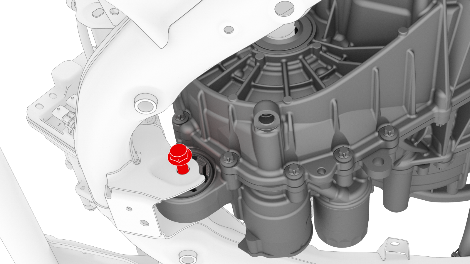
Remove the bolt that attaches the front drive unit to the front subframe.
-
Lower the front drive unit onto an appropriate surface, and then remove the drive unit sling hooks from the front drive unit.
| 1 | Remove the front subframe assembly from the vehicle. See Subframe Assembly - Front (Dual Motor) (Remove and Install). | ||
| 2 | Remove the steering rack. See Steering Rack (RWD) (Remove and Replace). | ||
| 3 | Install an axle extraction tool between the front drive unit and the inner joint of the LH front drive unit halfshaft, and then strike the end of the extraction tool with a dead blow hammer to unseat the halfshaft. | ||
| 4 | With assistance, remove the LH front drive unit halfshaft from the front drive unit, and then install a halfshaft plug into the opening of the gearbox. | ||
| 5 | Repeat steps 3 to 4 on the RH front drive unit halfshaft. | ||
| 6 | Release the locking tab, and then push the handle downward to disconnect the front drive unit inverter logic connector. | |
| 7 | Release the red locking tab, and then press down on the tab to disconnect the resolver logic connector. | |
| 8 | Release the grey locking tab, and then press down on the tab to disconnect the oil pump connector. | |
| 9 | Release the clip that attaches the front drive unit harness to the front drive unit motor. | |
| 10 | Release the clips that attach the front drive unit harness to the front drive unit inverter. | |
| 11 | Remove the front drive unit inverter-heat exchanger hose. See Hose - Inverter to Heat Exchanger - Front Drive Unit (Remove and Replace). | ||
| 12 | Remove the front drive unit inverter inlet hose. See Hose - Inverter Inlet - Front Drive Unit (Remove and Replace). | ||
| 13 | Position the subframe assembly under the gantry. | ||
| 14 | Install the drive unit sling on the gantry hook. | ||
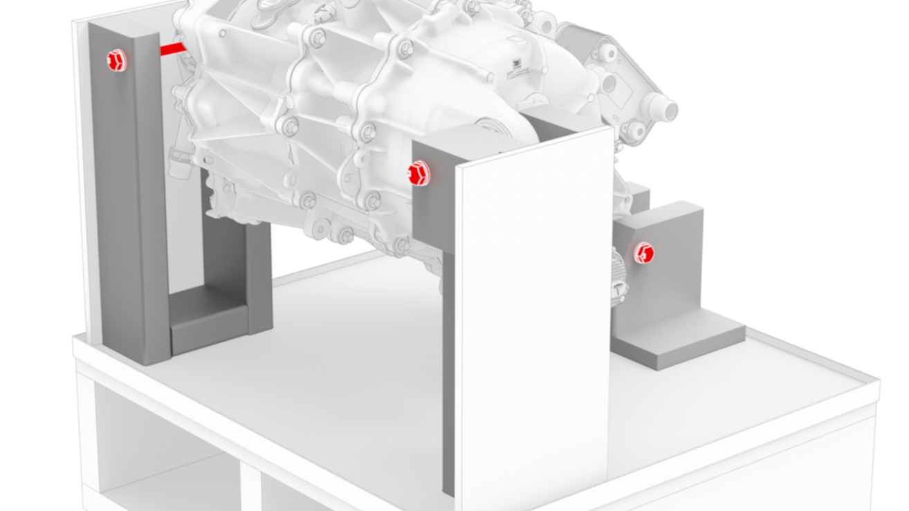
Front drive unit sling hook locations
| 15 | Install the drive unit sling hooks on the front drive unit. | |
| 16 | Slightly raise the gantry hook until the drive unit sling is taut. | ||
| 17 | Remove the bolt that attaches the front drive unit to the front subframe. | |
| 18 | Lift the front drive unit up and away from the front subframe. Note: Make sure not to move the rear front drive unit support posts.
| ||
| 19 | Lower the front drive unit onto an appropriate surface, and then remove the drive unit sling hooks from the front drive unit. |
Install
-
Position the new front drive unit under the gantry, and then install the drive unit sling hooks on the new front drive unit.
-
Remove the bolts that attach the front drive unit to the drive unit crate.
-
Install the bolt that attaches the front drive unit to the front subframe.
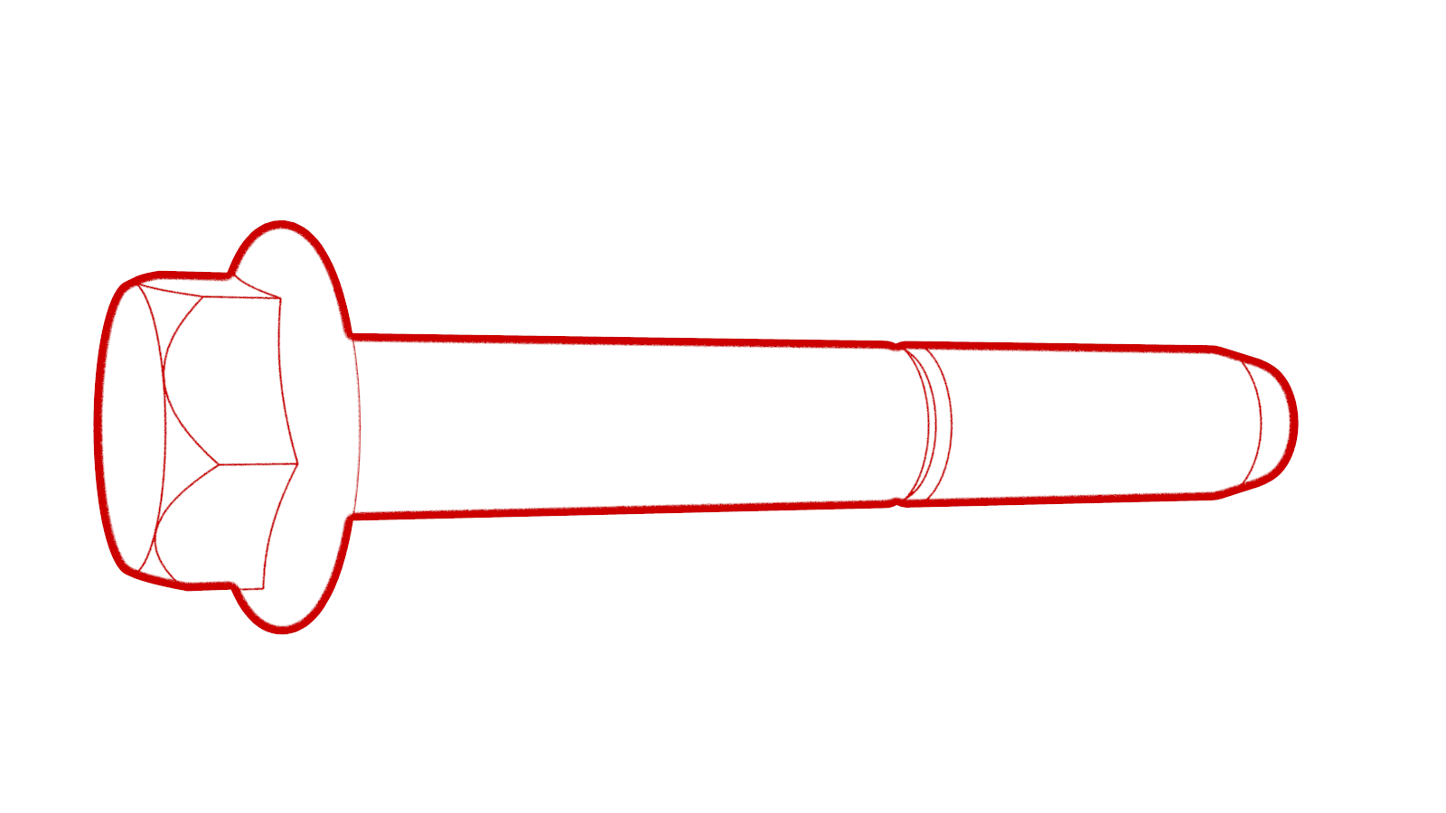 Torque 80 Nm
 -
Remove the drive unit sling hooks from the front drive unit.
-
Position the old front drive unit under the gantry, and then install the drive unit sling hooks on the old front drive unit.
-
Hand-tighten the bolts that attach the old front drive unit to the drive unit crate.
-
Slightly lower the gantry hook, and then remove the drive unit sling hooks from the old front drive unit.
-
Install the inverter-heat exchanger hose that was removed from the old front drive unit. See Hose - Inverter to Heat Exchanger - Front Drive Unit (Remove and Replace).
 Caution:Perform a push-pull test to verify that the hose is fully seated.
 -
If not preinstalled on the new front drive unit, install a new breather on the front drive unit.
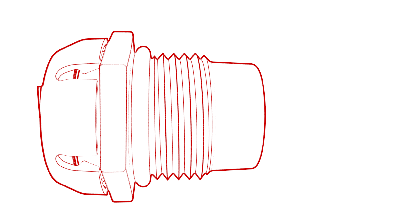 Torque 5 Nm
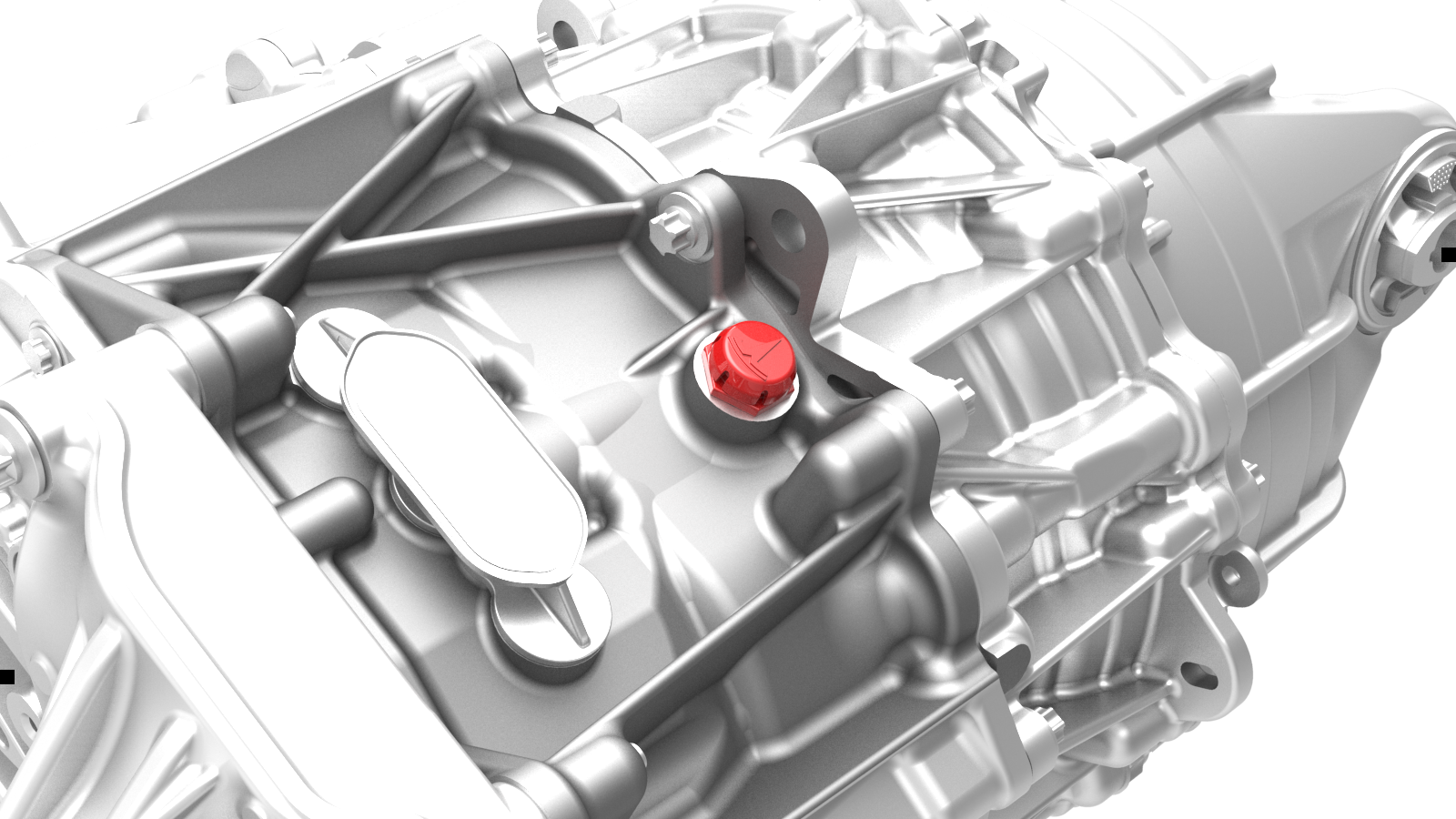
-
If not preinstalled on the new front drive unit, install a new 3-phase access label on the 3-phase lug cover.
-
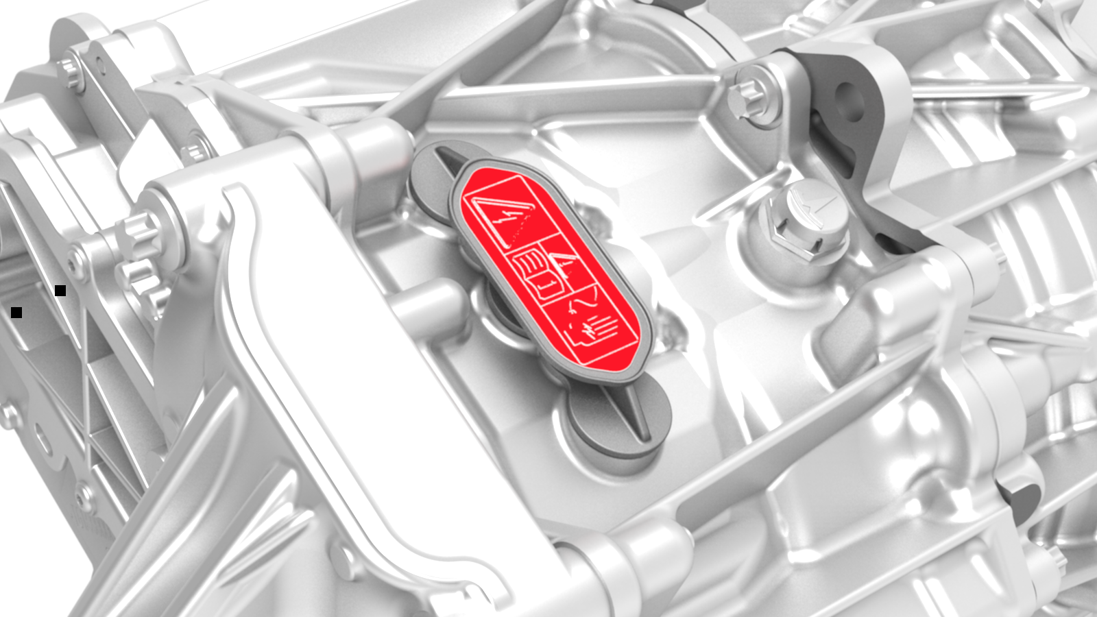
Install the clip that attaches the front drive unit inverter inlet hose to the exterior of the front drive unit gearbox.
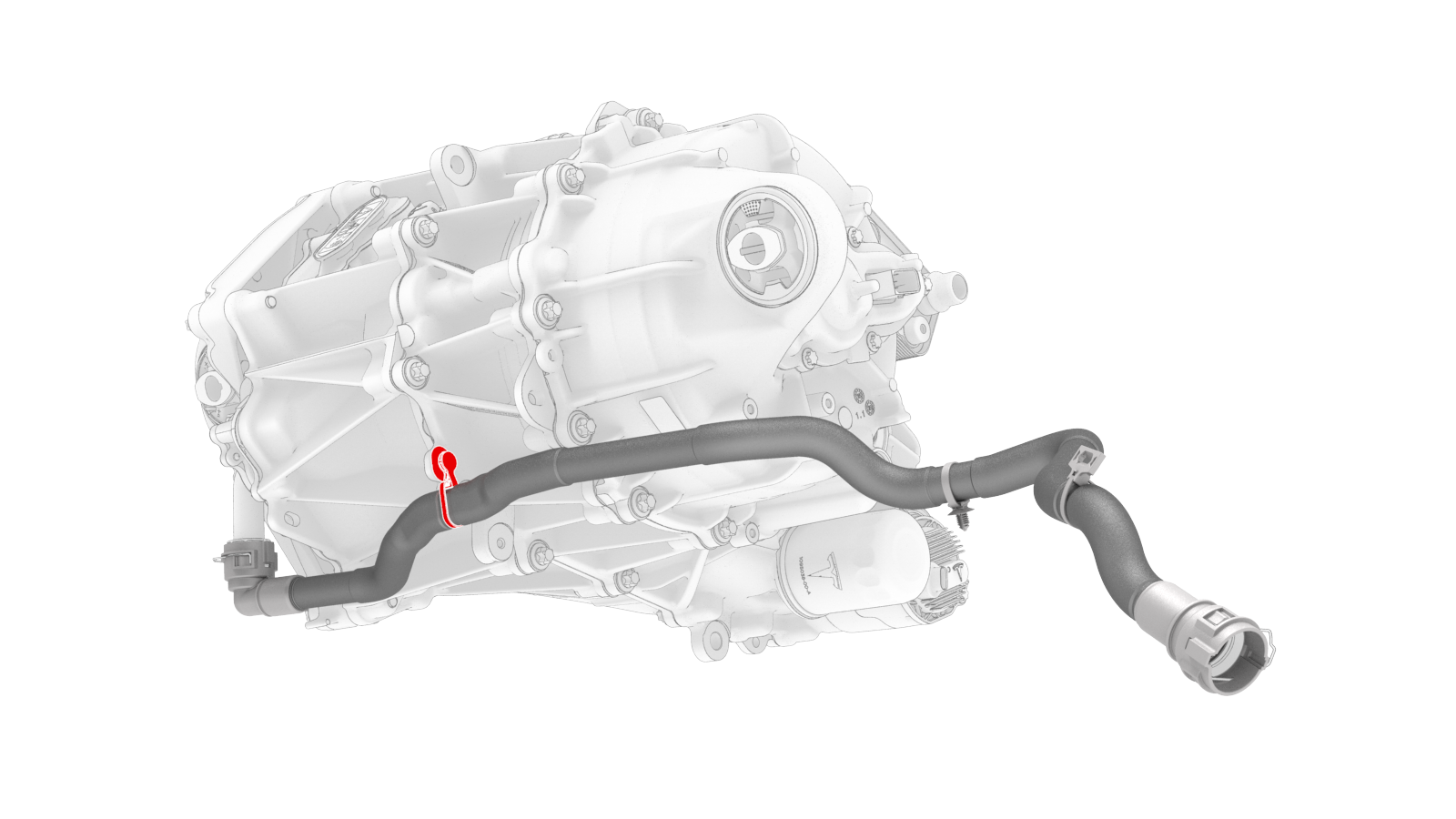 Other assemblies hidden for clarity
 -
Install the clip that connects the front drive unit inverter inlet hose to the front drive unit inverter coolant inlet.
Caution:Perform a push-pull test to verify that the hose is fully seated.
-
Install the clips that attach the front drive unit harness to the front drive unit inverter.
-
Install the clip that attaches the front drive unit harness to the front drive unit motor.
-
Connect the oil pump connector, and then engage the locking tab.
Important: Perform a push-pull test to verify that the connector is fully attached.
-
Connect the resolver logic connector, and then engage the locking tab.
Important: Perform a push-pull test to verify that the connector is fully attached.
-
Connect the front drive unit inverter logic connector, close the handle, and then engage the locking tab.
Important: Perform a push-pull test to verify that the connector is fully attached.
| 1 | Position the new front drive unit under the gantry, and then install the drive unit sling hooks on the new front drive unit. | |
| 2 | Slightly raise the gantry hook until the drive unit sling is taut. | ||
| 3 | Remove the bolts that attach the front drive unit to the drive unit crate. | |
| 4 | Lift the new front drive unit out of the drive unit crate, and then position the front subframe under the front drive unit. | ||
| 5 | Lower the front drive unit onto the front subframe. Note: Make sure not to move the rear front drive unit support posts from their previous positions.
| ||
| 6 | Install the bolt that attaches the front drive unit to the front subframe. Torque 80 Nm | |
| 7 | Lower the gantry hook until the drive unit sling is slack. | ||
| 8 | Remove the drive unit sling hooks from the front drive unit. | |
| 9 | Move the subframe to a working area. | ||
| 10 | Position the old front drive unit under the gantry, and then install the drive unit sling hooks on the old front drive unit. | |
| 11 | Lift the old front drive unit, and then position the empty drive unit crate under the old front drive unit. | ||
| 12 | Lower the old front drive unit into the empty drive unit crate. | ||
| 13 | Hand-tighten the bolts that attach the old front drive unit to the drive unit crate. | |
| 14 | Slightly lower the gantry hook, and then remove the drive unit sling hooks from the old front drive unit. | |
| 15 | Remove the drive unit sling from the gantry hook. | ||
| 16 | Install the inverter-heat exchanger hose that was removed from the old front drive unit. See Hose - Inverter to Heat Exchanger - Front Drive Unit (Remove and Replace). Caution: Perform a push-pull test to verify that the hose is fully seated.
| ||
| 17 | If not preinstalled on the new front drive unit, install a new breather on the front drive unit. Torque 5 Nm | |
| 18 | If not preinstalled on the new front drive unit, install a new 3-phase access label on the 3-phase lug cover. | |
Other assemblies hidden for clarity
| 19 | Install the clip that attaches the front drive unit inverter inlet hose to the exterior of the front drive unit gearbox. | |
| 20 | Install the clip that connects the front drive unit inverter inlet hose to the front drive unit inverter coolant inlet. Caution: Perform a push-pull test to verify that the hose is fully seated.
| |
| 21 | Install the clips that attach the front drive unit harness to the front drive unit inverter. | |
| 22 | Install the clip that attaches the front drive unit harness to the front drive unit motor. | |
| 23 | Connect the oil pump connector, and then engage the locking tab. Important: Perform a push-pull test to verify that the connector is fully attached.
| |
| 24 | Connect the resolver logic connector, and then engage the locking tab. Important: Perform a push-pull test to verify that the connector is fully attached.
| |
| 25 | Connect the front drive unit inverter logic connector, close the handle, and then engage the locking tab. Important: Perform a push-pull test to verify that the connector is fully attached.
| |
| 26 | Remove the halfshaft plugs from the gearbox, and then install the LH and RH front drive unit halfshafts in the front drive unit. | ||
| 27 | Install the steering rack. See Steering Rack (Dual Motor) (Remove and Replace). | ||
| 28 | Install the front subframe assembly on the vehicle. See Subframe Assembly - Front (Dual Motor) (Remove and Install). | ||
| 29 | Using Toolbox, perform a Service Firmware Redeploy. Select repair_network.ODIN_GTW_serviceFWRedeploy in the "Actions" tab. |