Inverter Coolant Leak Test
Correction code 4020201040202010
DRAFT
from-cad Warning:
This procedure was derived from pre-production computer models, and might not reflect the real-world situation. Warnings and cautions might be missing. Follow safety requirements and use extreme caution when working on or near high voltage systems and components.
Do not redistribute this content. Provide corrections and feedback to servicemanualfeedback@tesla.com.
- 1053600-00-C Drive Unit Pressure Test Fixture
- 1132185-00-B Kit, Coolant Leak Test Adapters, Model 3
- 1133843-00-AKit, Coolant Drain & Fill Adapters, M3
- 1135762-00-AKit, Svc Plug, Cooling Hose, Model 3
SPECIAL TOOLS
Drive Unit Pressure Test Fixture (1053600-00-C) |
Kit, Coolant Leak Test Adapters, Model 3 (1132185-00-B) |
Kit, Coolant Drain & Fill Adapters, M3 (1133843-00-A) |
Kit, Svc Plug, Cooling Hose, Model 3 (1135762-00-A) |
Procedure
-
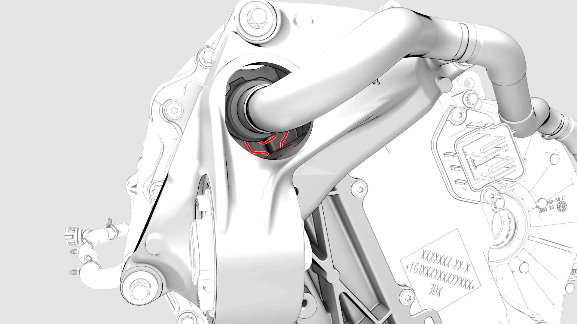
Disconnect the coolant outlet hose at the top of the inverter.
-
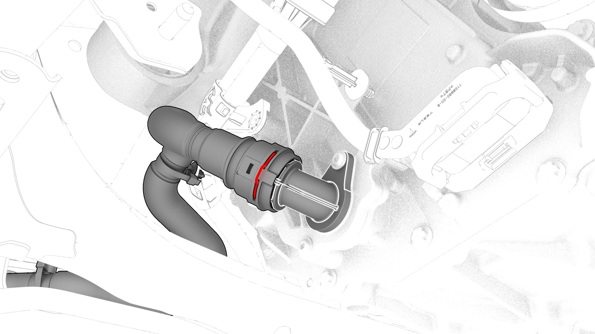
Disconnect the coolant inlet hose at the bottom of the inverter, plug the female fitting of the hose, and allow the inverter to drain.
-
Connect the hoses to the inverter.
 Caution:Perform a push-pull test to verify that the hose is fully seated.
| 1 | Disconnect 12V power. See 12V Power (Disconnect and Connect). | ||
| 2 | Remove the mid aero shield panel. See Panel - Aero Shield - Mid (Remove and Replace). | ||
| 3 | Position a coolant drain under the inverter. | ||
| 4 | Disconnect the coolant outlet hose at the top of the inverter. | |
| 5 | Plug the female fitting of the hose, and connect the coolant pressure test adapter to the inverter. | ||
| 6 | Connect the drive unit pressure test fixture to the coolant pressure test adapter. | ||
| 7 | Close both valves P1 (inlet) and P2 (outlet) on the test fixture, and connect a compressed air supply line. | ||
| 8 | Fully close the regulator, and then open P1 (inlet valve). | ||
| 9 | Set the pressure regulator of the test fixture to 26 psi. | ||
| 10 | Disconnect the coolant inlet hose at the bottom of the inverter, plug the female fitting of the hose, and allow the inverter to drain. | |
| 11 | Connect the coolant drain adapter to the bottom of the inverter, and direct the tube to the coolant drain. | ||
| 12 | Slowly open P2 (outlet valve) to speed the drain, and then close P2 (outlet valve). | ||
| 13 | Disconnect the coolant drain adapter, and then connect the coolant pressure test adapter plug to the inverter. | ||
| 14 | Open P2 (outlet valve) again, and allow at least 45 seconds for the pressure to stabilize to 26 psi. | ||
| 15 | Close P1 (inlet valve), record the starting pressure displayed, and start a 4 minute timer. | ||
| 16 | After 4 minutes record the ending pressure displayed. | ||
| 17 | Subtract the ending pressure from the starting pressure, and if:
| ||
| 18 | Disconnect the air supply from the test fixture. | ||
| 19 | Open P1 (inlet valve), and disconnect the test fixture from the coolant pressure test adapter. | ||
| 20 | Remove the coolant pressure test adapter and coolant pressure test adapter plug from the inverter, and the plugs from the hoses. | ||
| 21 | Connect the hoses to the inverter. Caution: Perform a push-pull test to verify that the hose is fully seated.
| ||
| 22 | Remove the coolant drain from under the vehicle. | ||
| 23 | Install the mid aero shield panel. See Panel - Aero Shield - Mid (Remove and Replace). | ||
| 24 | Connect 12V power. See 12V Power (Disconnect and Connect). | ||
| 25 | Perform a vacuum refill the cooling system. See Cooling System (Vacuum Refill). |